 Section 15 — Inspection
In-Plant Inspection for Existing Pressure Vessels
IPE Engineering Practice IPE-EP-15-4-3
Document number: IPE-EP-15-4-3 · Section: 15 — Inspection
SCOPE
- This practice defines the requirements and specifies responsibilities for the interval, external and internal inspection of existing plant pressure vessels, including towers, drums, spheres, spheroids, reactors, and heat exchangers.
- For the purposes of this Practice, an existing pressure vessel shall be regarded as a vessel which has been installed and which has been placed in service (commissioned).
- A revision bar indicates all changes made to this Revision.
2.0 REFERENCES
The latest edition of the following standards and publications are referred to herein:
STANDARDS AND PUBLICATIONS
| IPE Engineering Practices |
|---|
| EP 7–1–1 Pressure Vessels EP 7–1–3 Heavy Wall and Special Service Pressure Vessels EP 7–1–4 Supplemental Requirements for Pressure Vessels EP 7–1–5 Welding Requirements for Pressure Vessels EP 7–1–6 Metal Lining and Cladding EP 7–2–1 Pressure Vessel Internals EP 7–3–1 Rerating of Pressure Vessels EP 7–3–2 Repairs and Alterations to Pressure Vessels EP 8–1–1 TEMA Shell and Tube Heat Exchangers EP 8–1–3 Tube Bundle Replacement EP 10–3–4 Protective Coatings for Heat Exchangers EP 11–1–1 Internal Insulating and Refractory Lining EP 11–3–3Insulation Application – Vessels and Equipment EP 15–3–1Training, Qualifying and Certifying Personnel for Inspection of Plant Equipment EP 15–4–1 Principles and Practices for Inspection and Testing of In-Plant Equipment |
| API Standards |
| RP510 Pressure Vessel Inspection Code RP572 Inspection of Pressure Vessels |
| ASME Boiler and Pressure Vessel Codes |
| Sec VIII Division 1, Pressure Vessels |
STANDARDS AND PUBLICATIONS (Cont’d)
| National Board of Boiler and Pressure Vessel Inspectors |
|---|
| NB–23 National Board Inspection Code |
| TEMA |
| Standards of Tubular Exchanger Manufacturers Association |
DEFINITIONS
For the purposes of this Practice the following definitions shall apply:
- Existing Pressure Vessel – A commissioned container designed to withstand internal or external pressure that is built to a pressure vessel construction code.
- On–Stream Inspection – A half–life Inspection Code required thickness survey and evaluation of strategically located TML’s that may be performed while the vessel is in or out of service.
- Pressure Vessel Internal Inspection – This normally refers to, but is not limited to, a visual assessment of the internal surfaces and components, i.e., shells, heads, welds, linings, distributors, etc., for long range integrity evaluation (Occasionally, comprehensive inspection data evaluation, corrosion or CCTV probes, or Acoustic Emission tests may be substituted for some jurisdictional requirements).
- Pressure Vessel External Inspection – A quarter–life Inspection Code–required visual assessment of the conditions of a vessel’s external surfaces and components such as insulation, painting, fire proofing, foundations, and structures associated with the pressure vessel.
- PCMS – Acronym for Plant Corrosion Monitoring System; a computer program designed to statistically calculate corrosion rates and next inspection dates for equipment.
- T–Minimum – A Code required value used in calculating the remaining life of pressure vessels. It is the minimum required thickness of each component of the vessel calculated from equations in the applicable pressure vessel design code for the pressure and temperature stamped on the vessel.
- Vessel Thickness Monitoring Location (TML) – A strategic sample location or area of a vessel’s pressure boundary surface that has been selected and identified for monitoring shell thickness or other conditions.
- Vessel CCE (Common Corrosive Environment) – A term used to describe, for the purpose of corrosion rate monitoring, a section of a vessel shell where the corrosive conditions are approximately equal, taking into account the corrosive media (internally and externally), temperature, pressure, velocity, and the shell material.
GENERAL
- In certain locations, jurisidictional inspection requirements may vary from those discussed in this Practice. In such cases where there is conflict the jurisdictional requirements shall apply.
INSPECTION PERSONNEL
- Personnel performing inspection of pressure vessels and vessel components shall be qualified in accordance with EP 15–3–1.
ASSIGNMENT OF VESSEL CCE’S AND THICKNESS MONITORING LOCATIONS (TML’S)
- Each vessel that is monitored for corrosion shall have CCE’s assigned with unique identifiers as a master reference for monitoring the rate of corrosion and maintaining corrosion data in the vessel record. A careful review of the probable corrosion exposure patterns or historical corrosion information in each vessel shall be performed before assigning CCE’s for the vessel. Guidance for establishing CCE’s are as follows:
- CCE’s shall be determined by a combination of: process operating conditions; 20ºF to 50ºF temperature ranges; vapor, liquid states and interfaces; past experience with the type of vessel and the nature of the corrosion; and specification breaks in shell materials, liners, or cladding.
- CCE boundaries shall be described so that they can be accurately identified in the field.
- Columns shall contain at least three CCE’s, unless operating conditions or experience indicates fewer are needed. These are: a bottom CCE below the bottom tray, a central CCE between the bottom and top tray, and a top CCE above the top tray. Trays usually have both vapor and liquid environments. Packed towers shall be treated similarly with one CCE below the bottom bed, one within the packing bed(s), and one above the top of the packing bed(s).
- TEMA type exchanger shells can usually be divided into at least two CCE’s: shell side, and channel side.
- Drums may generally be considered as containing at least one CCE and often both vapor and liquid environments.
- Vessel design and operating complexity may dictate additional CCE’s. When it is difficult to determine where and how many CCE’s are required, operating and/or engineering personnel shall be consulted to assist in identifying CCE’s.
- Once CCE’s for a vessel have been established, if conditions warrant, CCE’s may be subdivided or combined. The date and reason for the change shall be documented in the vessel inspection record.
- Thickness monitoring locations (TML’s) shall be identified for each CCE in the vessel. Each TML shall be adequately identified either on the vessel and/or on a vessel sketch so subsequent readings are taken at the same location. Requirements for TML’s are as follows:
- Each TML shall be given a unique identifier so that it can be associated with the assigned CCE and a given location on the vessel.
- TML’s shall be located so that they will provide a representative measure of the corrosion activity occurring within the vessel CCE.
- TML’s shall be located in the following areas where practicable:
- Each shell course.
- Each vessel head.
- The internal circumference of each nozzle unless externally accessible.
- The number and location of TML’s depend on several factors:
- The level of corrosion activity occurring within the CCE and the number of expected critical locations.
- Whether the corrosion is uniform or localized.
- The number of nozzles and other appurtenances located within the CCE including both top and bottom locations.
- Whether the vessel is insulated or un–insulated.
- Accessibility of the vessel shell where the CCE is located.
- For insulated vessels, inspection access ports designed to prevent the ingress of moisture under the insulation shall be installed. This access port shall then define the TML.
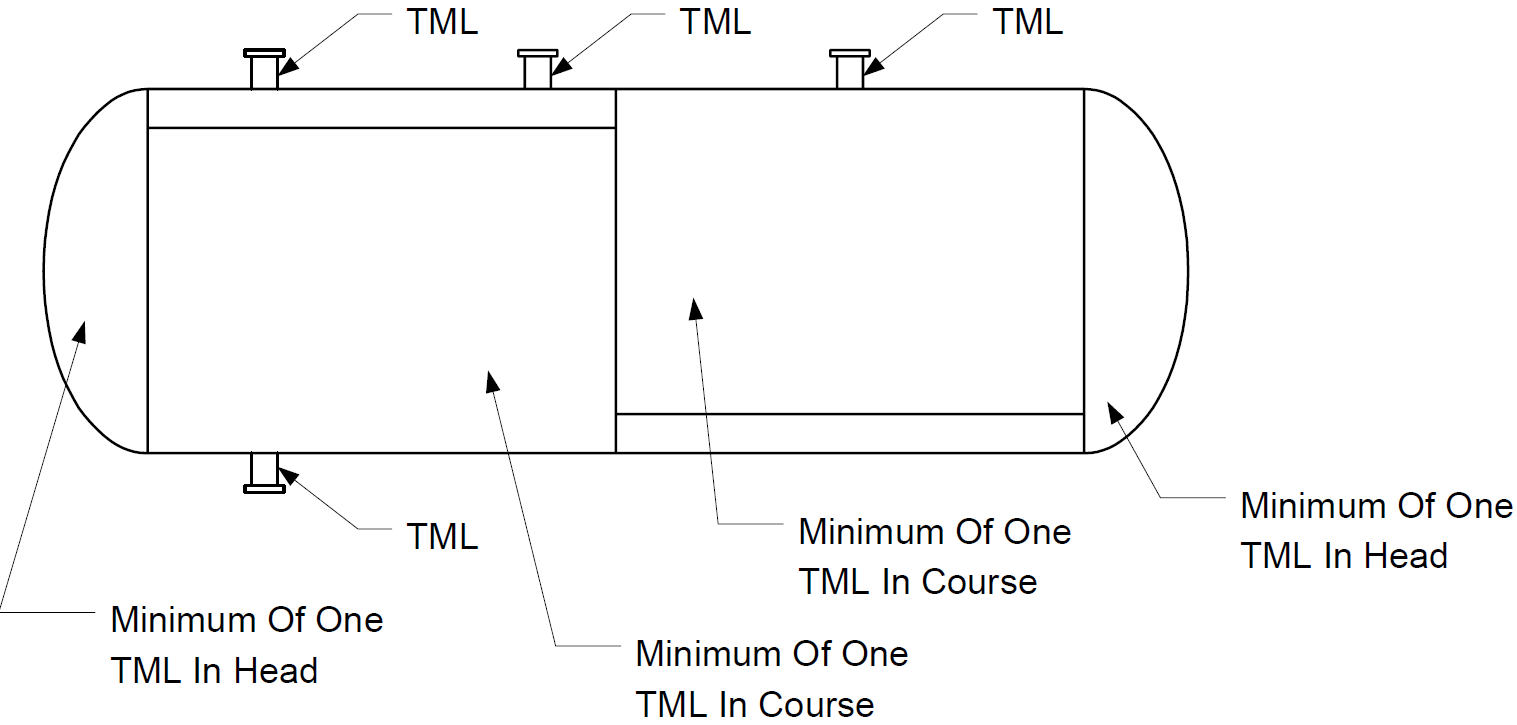
- Figure 1 through Figure 3 provides a guideline for the assigning of TML’s for towers, drums, and exchangers.
- The number of TML’s may be increased to improve the corrosion information on a vessel when pressure vessel internal inspection indicates the initial number and location of TML’s is not adequate to provide the information.
ON–STREAM INSPECTION
- On–stream inspection of existing pressure vessels is a Code–required inspection that may be conducted on–stream or during a shutdown, but shall be performed at least every 10 years, at the corrosion half–life, or in accordance with PCMS, whichever is earlier. The on–stream inspection thickness monitoring plan shall be developed by the Inspector following a review of critical corrosion criteria such as provided by PCMS.
- The CCE sampling plan will include the TML’s chosen by the Inspector. See Section 6.0 of this Practice for discussion on establishing TML’s.
- Within each TML area, the vessel thickness shall be scanned to obtain a minimum reading. This minimum reading shall then be recorded as the thickness value for the TML.
- A consistent, experienced reading technique coupled with reliable equipment shall be employed in an effort to obtain accurate field readings. Only actual field readings will be reported.
- Profile radiography shall be considered for inspection of small attached vessel piping.
- If a large scatter in the thickness readings at a TML is experienced, additional areas adjacent to the TML may need to be scanned until the nature of the condition can be assessed. The verified minimum wall thickness reading shall be recorded and the location identified. Such conditions may require engineering evaluations. All conditions of this sort shall be noted in the vessel record.
- All CCE’s planned for the vessel on–stream inspection will be surveyed in similar manner.
- When available, statistical corrosion rate analysis, such as provided by PCMS, of the vessel thickness survey results must satisfy the Inspector that the vessel is fit for continued service.
PRESSURE VESSEL EXTERNAL INSPECTION
- External inspection of existing pressure vessels is a Code–required inspection. It shall be performed preferably while the vessel is in operation when serious problems are normally more revealing. The inspection must be conducted at least every 5 years, at the quarter corrosion rate life, or in accordance with PCMS. The following items are examples that shall be considered in the pressure vessel external inspection program.
- Ladders, walkways, platforms, and stairways shall be inspected for the following conditions:
- Corroded, bent, broken, or missing structural parts.
- Loose or missing bolting.
- Worn stair treads and rungs.
- Foundations and supports shall be inspected for the following conditions:
- Expansion freedom.
- Spalling, cracking, or settling of concrete or steel reinforced concrete foundations.
- Evidence of anchor bolt corrosion and distortion.
- Evidence of loose anchor bolt nuts.
- Corrosion, distortion, and cracking of steel supports and skirts.
- Condition of fireproofing on skirts.
- Nozzles and adjacent shell areas shall be inspected for the following conditions:
- Distortion, bulging, cracking.
- Leakage
- Pitting and other indications of corrosion.
- Vessel grounding connections shall be examined to ensure good electrical contact and condition of grounding bolts, bands, straps, and rods.
- Protective coatings shall be examined for evidence of deterioration, such as chalking, peeling, streaking, or spalling.
- Vessel shells shall be inspected for the following conditions:
- Distortion, bulging, blistering
- Leakage
- Pitting
- Insulated vessels shall have the insulation inspected for the following conditions:
- Loose, corroded, or deteriorated insulation support systems.
- Breakage, tears, or other breech of weather proofing which would permit water to penetrate the insulation (Investigate any signs of invasion).
- Insulated vessels having shell temperatures between –20ºF and 300ºF for extended periods of time or frequently cycled through this temperature range shall be inspected periodically for evidence of corrosion under insulation.
- The frequency and extent of inspection depends on factors such as plant location, presence or absence of protective coatings, and proximity to cooling towers and other sources of moisture.
- Any breaks or tears in the insulation or weather sheathing shall be removed, the shell inspected for external corrosion in that area and the insulation properly repaired.
- The Inspector shall also consider the possibility of the corrosion occurring remote from areas of insulation damage and inspect the shell in the areas of insulation support rings, reinforcing rings, etc.
PRESSURE VESSEL INTERNAL INSPECTION
| CAUTION: Personnel entering any confined area must be aware that they may be vulnerable to special unapparent dangers as well as to hazardous atmospheres. Such dangers are normally well controlled, but changing conditions require continued alertness. Consequently, personnel must observe all hot work precautions, safety signs and tags, and use special protective equipment and standbys as necessary. |
|---|
- Vessels in Code defined non–corrosive service (with at least 5 years of confirmed corrosion rates of less than 0.005 IPY) need not be internally inspected as long as there are no external inspection concerns, the operating temperature does not exceed the lower temperature limits for the creep rupture range of the construction metal (about 700ºF for carbon steel) and the vessel contents are not subject to inadvertent contamination by corrosives.
- Internal inspection of existing pressure vessels shall be performed as opportunity for access presents itself or in accordance with the EP 15–4–1.
- An initial visual inspection shall be performed as deemed necessary by the Inspector, process, or maintenance management personnel. Such inspection shall be appropriate to identify specific conditions of concern with special attention to the following:
- Physical damage to internal parts such as trays, tray supports, weirs, baffles, etc.
- Unexpected corrosion to vessel shell or internal parts.
- Accumulation of sludge, corrosion product, deposits, or other material that may contribute to accelerated corrosion or deterioration of the vessel or its internals.
- Internal vessel access shall be provided to surfaces and vessel internal parts to be inspected and special cleaning performed, when necessary, so that a thorough inspection may be performed.
- After review of the last inspection report, the Inspector shall inspect as deemed necessary the following to identify special inspection concerns:
- Vessel shells, heads, nozzles, and weld seams for the following conditions based on past history and service duty:
- Localized corrosion, pitting, erosion, and impingement damage.
- Blistering, bulging, buckling, or distortions
- Cracking, especially at weld locations and distortions.
- Laminations.
- Pinholes.
- Vessel internals for the following conditions:
- Deterioration or cracking of tray, baffle, grid, or piping supports and welds, deterioration or cracking of internal stiffeners, erosion of impingement plates.
- Distortion, bulging, blistering, or buckling of weirs, baffles, trays, supports, and impingement plates.
- stagnant and turbulent locations.
- Locations in large vessels where temperature gradients and fatigue may occur.
- Missing, loose, or deteriorated bubble caps, weirs, etc.
- Missing, loose, or deteriorated internal bolting.
- Deteriorated, cracked, or damaged internal piping.
- Internal linings (both metallic and refractory) for corrosion, pitting, cracking, spalling, leakage.
- Internal coatings for evidence of deterioration.
10.0 SERVICE SPECIFIC INSPECTION
Vessels which are exposed to unusual service conditions and which may exhibit deterioration requiring special inspection methods for damage detection shall have a specific inspection plan developed detailing the method, extent, and frequency of such inspections.
11.0 INSPECTION OF REMOVED VESSEL COMPONENTS
Components which have been removed from the vessel shall be examined for evidence of deterioration or other conditions which would preclude reinstallation.
12.0 INSPECTION OF REPLACEMENT COMPONENTS
Prior to reinstallation, any replacement parts or components shall be inspected to ensure correctness of material and assembly per the requirements of EP 15–1–4.
13.0 VESSEL REPAIRS AND ALTERATIONS
The Inspector shall assure that vessel repairs and alterations are performed, inspected, and documented in strict conformance with the requirements of governing codes, standards, and EP 7–3–2.
REPAIR INSPECTION
- Upon completion of all required repair work, the vessel shall receive a final inspection to ensure the completeness and adequacy of repair.
- When integrity pressure tests of the vessel are required by code or jurisdiction they shall be witnessed and documented in the inspection records. Such records shall include the date, test duration, test pressure, temperature of the test medium, ambient air temperature, and name(s) and signature(s) of the person(s) witnessing the test.
RECORDS AND DOCUMENTATION
- A sketch of the vessel shall be made which accurately identifies TML’s.
- The name(s) of the personnel who performed the inspection and the date of inspection of the vessel shall be recorded on the vessel inspection field report.
- The thickness measurements shall be used to determine corrosion rates, next inspection dates in conjunction with the requirements of EP 15–4–1 and APl 510, and retirement dates for vessels or through the use of computer software such as PCMS. Calculation of corrosion rates shall be in accordance with the following:
- Corrosion rates shall be calculated for each TML measured and average corrosion rates shall be calculated for each CCE in the vessel.
- The corrosion rates calculated shall be used to determine maximum point rates and maximum average CCE rates.
- The calculated maximum corrosion rate and T–Minimum values for the vessel shall be used for determining the next quarter–life and half–life inspection date.
- Inspection findings and their interpretation shall be reported and retained in a permanent equipment history file record system. The report, including all test records, and the sketch shall become a part of the permanent record or the information shall be transferred to a permanent data base. Additional requirements are as follows:
- Inspection findings including their impact on future operations shall be reported relative to their location in the vessel.
- Inspection findings including reference to previous analyses shall be reported in sufficient detail to permit relocation and evaluation of the reported condition.
- Additional notes, sketches, or documents shall be appended to the equipment report if required to more fully describe the inspection findings.
RESPONSIBILITIES
- The Plant Inspection Authority or his delegate shall be responsible to:
- Serve as Final authority on all matters concerning inspection, including final acceptance.
- Assign personnel associated with the inspection operation.
- Determine if cleaning is needed to achieve a satisfactory thorough inspection.
- Evaluate inspection findings, and provide APl 510 and NBIC evaluation of potential repairs.
- Prepare or endorse required Inspection Repair Scopes.
- Assure equipment history record files are maintained.
- The Mechanical Contractor, Owner’s Supervisor, or Owner’s Engineer or his delegate shall be responsible to:
- Notify the appropriate Inspector when a vessel has been opened and flushed, and is ready for internal inspection.
- Support any required operations involving vessel inspection, repair or alteration.
- The Inspector shall be responsible to:
- Perform on–stream, external and internal inspection of the vessel and components in accordance with this procedure.
- Obtain ultrasonic thickness readings of vessel shell, heads, and nozzles.
- Establish CCE’s and TML’s as necessary.
- Physically identify TML’s on the equipment or on a vessel sketch that will assure future location for accurate data development.
- Accurately record TML thickness findings.
- Observe and document that all Code repairs and alterations have been performed correctly.
- Perform repair/alteration quality inspection and Code acceptance as required including integrity pressure testing of the vessel.
- Review and establish vessel corrosion rates, next inspection dates, and repair/retirement dates.
- Evaluate the inspection results, and make recommendation for improvements, repairs/alterations and renewals for safe operations. Review and change EP 15–4–1 grades and intervals as appropriate.
- Provide sketches and all test records to appropriate personnel as necessary.
- The Operations Department Representative shall be responsible to:
- Determine cleanliness for satisfactory operation of pressure vessels, and sign off for closing vessels.
- Witness closing of internal and external manways of pressure vessels.
17.0 FIGURES
FIGURE 1
MINIMUM NUMBER OF COMMON CORROSION ENVIRONMENTS (CCE) AND THICKNESS MONITORING LOCATIONS (TML) FOR A TYPICAL COLUMN
FIGURE 2
MINIMUM NUMBER OF COMMON CORROSION ENVIRONMENTS (CCE) AND THICKNESS MONITORING LOCATIONS (TML) FOR A TYPICAL EXCHANGER
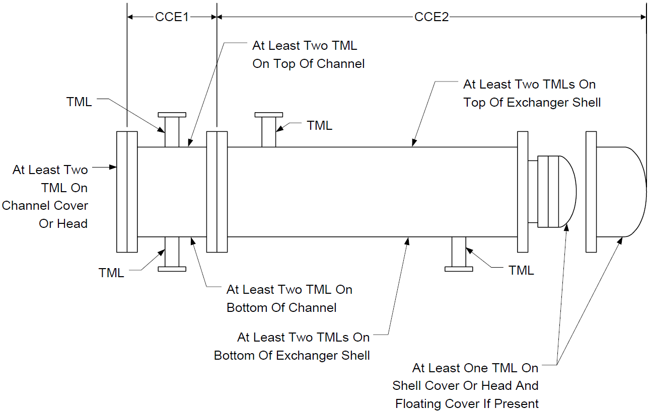
FIGURE 3
MINIMUM NUMBER OF THICKNESS MONITORING LOCATIONS (TML) FOR A TYPICAL DRUM
© 2026 Inflection Point Engineering, LLC. All rights reserved. The content of this page — including calculation methods, reference data, written analysis, interactive tools, and source code — is the intellectual property of Inflection Point Engineering, LLC and is protected under applicable copyright, trademark, and trade secret laws. Unauthorized reproduction, redistribution, modification, or derivative use in whole or in part is prohibited without prior written consent.
Disclaimer. This material is provided for informational and educational purposes only and does not constitute professional engineering advice. Calculations, reference data, and methodologies are based on published standards and accepted engineering practice but are not a substitute for engineering judgment, site-specific analysis, or review by a licensed Professional Engineer. Inflection Point Engineering, LLC makes no warranties, express or implied, regarding the accuracy, completeness, or fitness for a particular purpose of any content presented here, and shall not be liable for any direct, indirect, incidental, or consequential damages arising from its use. Users assume all risk associated with applying this content to real-world design, operations, or decisions.
© 2026 Inflection Point Engineering, LLC. All rights reserved.