 Section 15 — Inspection
Ultrasonic Examination
IPE Engineering Practice IPE-EP-15-2-6
Document number: IPE-EP-15-2-6 · Section: 15 — Inspection
SCOPE
- This practice covers the minimum requirements to perform and monitor the Ultrasonic Inspection method by IPE Inspectors and contractors. Included are requirements for obtaining thickness measurements at elevated temperatures.
- Inspection contractors whose procedures have been submitted and approved by IPE
Inspection personnel may perform Ultrasonic Inspections.
- Any deviation to this practice shall be approved by the procedure described in EP 1–1–3.
- An asterisk ( * ) indicates that a decision by the Owner’s Level III or Inspection Authority is required or that additional information is furnished by the Purchaser.
- (*) Special Contractor - procedures for automated ultrasonic testing or other applications shall be approved by the Inspection Authority before testing begins.
REFERENCES
The latest edition of the following standards and publications are referred to herein.
STANDARDS AND PUBLICATIONS
| IPE Engineering Practices |
|---|
| EP 1–1–3 Deviations to IPE Engineering Practices |
| ASME Codes |
| Sec V Non–Destructive Examination |
| ASNT |
| TC–1A Certification of NDE Personnel |
| ASTM Codes |
| 114 Pulse-Echo Contact Method, Measuring Thickness 797 Pulse-Echo Straight–Beam, Examination by the Contact Method |
DEFINITIONS
- Couplant - Liquid or semi liquid required between the face of the search unit and the examination surface.
- CRT - Cathode Ray Tube (Visual display used in Ultrasonic inspection).
- Owner - Inflection Point Engineering, LLC.
- Purchaser - The party placing a direct purchase order. The purchaser is the Owner’s designated representative.
- Plant Inspection Authority - That person or body appointed by Management to be responsible for examination and certification of equipment utilized within the plant. Management may appoint more than one Inspection Authority in order to cover specialized equipment such as rotating, instrumentation and electrical equipment.
- TML - Thickness Measurement Location
- POM - Point of Measurement
DESCRIPTION OF TEST METHODS
- This procedure may be used with the following Ultrasonic techniques:
- Ultrasonic Thickness Measurements with Digital Meters
- Pulse Echo Straight Beam Ultrasonic Inspection Using A Scan Presentation for Flaw Detection in Rolled Plates
- Pulse Echo Straight Beam Ultrasonic Inspection Using A Scan Presentation for Flaw Detection in Castings
- Pulse Echo Thickness Measurements Using A Scan Presentation
RESPONSIBILITY
- The Level III shall be responsible for the content of this procedure and subsequent revisions.
- The Inspection Authority shall be responsible to assure that only certified personnel perform these examinations.
CERTIFICATION
- Personnel performing examinations to this procedure shall be certified to the requirements of EP 15–3–2 or an approved contractors written practice that meets the requirements of ASNT- TC-1A.
- This procedure or an approved contractors procedure shall be available during these examinations.
SAFETY
- When using AC powered ultrasonic equipment for examinations, or other AC power lighting equipment, the inspector should take care to avoid electrical shock. Ground fault circuit breakers should always be used along with explosion proof connections, where required, in operating facilities.
- Worn electrical cords and other equipment should be discarded.
- All applicable plant safety rules shall be followed when performing testing.
- All contractor safety rules and procedures shall be followed by contractor employees working in plant.
- All U/T equipment manufacturer’s safety recommendations for equipment used in the U/T process shall be followed.
- Transducer cables (connectors) shall not be connected or disconnected to or from the U/T instrument with the power on while in operating units. Sparking may occur if the instrument is turned on.
SURFACE PREPARATION
- When performing thickness measurements, it is possible to get accurate measurements through tightly bonded coatings utilizing properly setup equipment with A scan presentations or digital instruments specially equipped.
- When this equipment is not used or coatings are not tightly bonded, preparation by grinding, chipping or buffing is necessary to remove paint, corrosion or to smooth out pits or other erroneous surface conditions which would render examination results inaccurate or false.
- When performing flaw location techniques, the test surface shall be free of all coatings, heavy mill scale or corrosion.
- The surface temperature of the test specimen shall not exceed 200oF unless inspected with special designed instruments with high temperature compensation, transducer assemblies and couplants. The temperature ranges for these transducer assemblies and couplants shall be limited to the manufacturers’ recommendations.
EQUIPMENT
- The instrument shall be capable of generating, receiving and amplifying high frequency electrical pulses at such frequencies and energy levels required to perform the examination and display this information in a digital or CRT display.
- The size of the transducer shall be between 1/16” and 1”.
- Transducers shall be used within the manufacturers rated temperature range.
- High temperature transducers should be used intermittently on hot surfaces. Transducers should be cooled to less than 120°F between measurements by:
- Contact with a reference block. Cooling by placing the transducer on a reference block is preferred because it is faster than air cooling and provides a calibration check.
- Contact with cool water.
- Air cooling.
- Typically, high temperature transducers can be left on surfaces of 150°Fto 400°F for up to 20 seconds before cooling, and for up to 10 seconds on parts between 400°F and 1000° F. In some cases, however, the couplant will degrade in less time than this.
- The frequency shall be between 1.0 MHz and 5 MHz. Instruments operating at other frequencies may be used if equal or better sensitivity can be demonstrated and documented. For thickness measurements, any frequency capable of resolving the thickness range may be used.
- Measurement doubling may occur without warning while taking thickness readings on thin parts; typically less than 0.10 inches.
- The doubling point of each model transducer and gauge combination shall be determined. Steel feeler gauges can be used to make this determination.
- While measuring plant equipment, no thickness reading shall be recorded as valid readings which are less than two times the actual feeler gauge thickness where doubling occurs, plus 25%.
- While taking thickness readings on plant equipment, if values are measured which are less than the value calculated above, these readings shall not be used, and a different gauge and/or transducer must be used with a lower doubling threshold to make these measurements.
- Different transducers and instruments can double at greater thickness. Also, worn or reconditioned transducers can double at greater thickness. Reconditioned transducers shall be rechecked for doubling.
EQUIPMENT CALIBRATIONS
- Each piece of ultrasonic inspection equipment shall be calibrated at least once a year, or after each time that it has been subjected to major electrical repair, periodic overhaul, or damage.
- Equipment used to perform straight beam Flaw Detection to ASME Sec. V shall be calibrated every 3 months.
- A calibration sticker shall be fixed to the instrument with the date of calibration, date of re– calibration and signature of the person performing the calibration.
- A calibration certificate shall be maintained as part of the required quality documentation.
FIELD EXAMINATION CALIBRATIONS
- Calibration - Shall be performed in accordance with the equipment manufacturer’s operation manual and verified in accordance with Section 13.2 of this procedure.
- Calibration or verification shall be performed at a minimum; immediately before tests are conducted and at the end of each examination session, when examination personnel are changed, at any time that a malfunction is suspected, whenever the test instrument is turned off or on, and periodically throughout the examination period.
- The temperature of the calibration block shall be within +/- 25 Degrees Fahrenheit of the test specimen, unless the instrument is capable of making temperature corrections or other temperature compensation methods are used, such as noted in Section 14.
- Calibration shall be performed using calibration blocks made of the same material or with the material of the same nominal acoustic velocity, as the material being tested. If during any verification of calibration, it is determined that the test has been performed with the test unit out of calibration, all tests conducted since the last known calibration shall be redone.
COUPLANTS
- (*) Water cellulose gel, oil, grease or other products acceptable to IPE Inspection personnel are accepted couplants for this procedure. Couplants used by contractors must be included in their procedure.
- Corrosion inhibitors, wetting agents or both may be used.
- Couplants must be used within the manufacturers published temperature range. Sulfites and halogens in couplants shall be limited to less than 1%. On 300-series stainless steels, operating at elevated temperatures, low chloride or no chloride couplants shall be used, and all couplant shall be removed from the surface following completion of measurement.
- When taking thickness measurements on surfaces at 500ºF and higher, the couplant shall be applied to the face of the transducer.
- At temperatures above 500ºF, couplant shall be removed from the transducer face and the TML surface after each measurement.
- EXAMINATION REQUIREMENTS FOR ULTRASONIC INSPECTION THICKNESS MEASUREMENTS USING DIGITAL METERS
- The step wedge or other calibration block shall include a step less than, and a step greater than the expected thickness of the part being tested.
- The thickness calibration verification procedure shall be performed as follows:
- Set the transducer in Position #1 as shown in Figure 1.
- Adjust the controls until the instrument’s digital display reading coincides with the actual thickness of the block at position.
- Set the Transducer in Position #2 as in Figure 1.
- Adjust the controls until the instrument’s digital display reading coincides with the actual thickness of the block at Position #2.
- Repeat operations a through d until the instrument displays the correct thickness (within plus or minus one percent (1%) of actual thickness) without further adjustment of the controls through- out the wedge thickness range (each step).
- Procedure
- Apply couplant to the test specimen or the Transducer.
- Contact the transducer to the test specimen.
- The inspector or U/T Technician shall manipulate the transducer at each POM within the TML sufficiently to assure accurate measurements are obtained.
- A minimum of 2 measurements shall be obtained at each POM.
- Record the minimum REPEATABLE thickness at a POM for the TML.
- The acoustic barrier separating the two elements on dual element transducers shall be placed perpendicular to the long axis of the pipe or vessel being measured.
- The transducer face shall be held as flat as possible against the TML surface with firm steady pressure. Rocking to obtain the lowest measurement is permissible.
- (*) Record the U/T information in Table 3 or equivalent and/or data loggers if approved by the responsible IPE Inspector.Table 3
- Ultrasonic thickness measurements shall be recorded to an accuracy of (0.01 inches). If it is possible, the digital ultrasonic instrument shall be set to display to the same accuracy
(0.01 inches). If this is not possible, the inspector or technician shall record to the same accuracy (0.01 inches). No rounding up or down is allowed.
- The number and locations of readings shall be as directed by the IPE Inspector responsible for the work or as noted on IPE sketches, or other documents. Any reading that cannot be taken, due to part geometry shall be so noted on the Ultrasonic Test Inspection Report – Table 3 or 4, or other approved document.Table 3 4,
TEMPERATURE CORRECTION
- Because the ultrasonic velocity of steel changes as a function of temperature, some form of temperature correction must be applied to ultrasonic thickness measurements made at elevated temperatures.
- There are two recommended correction methods; the Calculated Temperature Correction Method and the Velocity Adjustment Method.
- Calculated Temperature Correction
- The thickness meter should be calibrated at ambient temperatures and all thickness readings are taken using this calibration. The thickness displayed on the digital thickness gauge is not the actual wall thickness and is referred to as the “measured” wall thickness. The measured wall thickness and temperature are recorded for correction by calculation.
- Surface temperatures should be measured to the nearest 50°F.
- Table 1 shows the thickness that would be measured on a one inch thick, carbon steel block at different temperatures with a room temperature calibration. All of the measured values in Table 1 would be corrected back to 1.000 inches by the calculation. (This method is also valid for stainless steel).
- To obtain a corrected thickness value, the following correction formula may be used: Velocity = 2325 FPS - [0.2325 ( Surface Temperature - 70)]
- Instrument Velocity Correction
- The instrument velocity correction method requires the velocity setting of the thickness gauge to be reset for each thickness reading taken.
- The velocity setting is based on the surface temperature according to Table 2 for carbon steel. Materials such as stainless steel cannot be tested using these velocity values.
- After the velocity is reset to the appropriate value (per the manufacturer’s operation manual), the thickness is measured. The thickness meter reads the actual thickness because the change in velocity in the steel has already been corrected for.
- Record the minimum repeatable wall thickness at a measuring point within the TML.
- Ultrasonic readings at elevated temperatures are more difficult to obtain than similar readings at ambient temperatures. Consistency and accuracy can be improved as follows:
- Prepare the surface for first and subsequent readings by smoothing and cleaning the test surface.
- Apply couplant to the transducer face, not to the test piece (Couplant placed on the pipe or vessel surface may degrade before the measurement is made).
- Allow extra time per reading. Compared to ambient readings, high temperature readings take extra time to prepare the surface, and to cool the transducer after readings. Taking readings too quickly may lead to transducer damage and/or measurement error.
- Minimize twisting or moving transducer on hot surfaces. At the upper end of a couplant’s temperature range, transducer movement frequently causes loss of couple.
- Take at least one reading per location and check calibration frequently. Averaging three readings at a location has been shown to improve repeatability by 20% to 40% over the single reading technique.
- EXAMINATION REQUIREMENTS - LOCATION OF FLAWS USING A SCAN PRESENTATION FOR FORGED OR ROLLED MATERIALS
- The Reference Standard - IIW Block (type I or II) or a Step Wedge shall be used as a calibration standard.
- Distance Calibration -
- Set the transducer in position A or B (Figure 2) as required by part length, i.e. 1, 5, 10 range.
- Adjust the sweep and delay controls until the multiple indications from the calibration block appear at a maximum range of “T” * 1.25 = Instrument Calibration Range. (T = Part Thickness)
- Amplitude - Set the back reflection from the opposite side of the test specimen to between 70% and 80% of FSH (full screen height).
- Sizing of indications that are smaller than the face of the transducer (finite).
- Move the transducer toward the area of the discontinuities until an indication on the CRT screen begins to form.
- Mark the leading edge of the transducer on the part.
- Repeat steps A and B until the discontinuity is completely mapped out.
- Sizing of indications larger than the face of the transducer (infinite).
- Maximize the signal from the discontinuity on the CRT.
- Move the transducer until the indication on the CRT drops half (6 dB) of the original maximized signal height.
- Mark the center of the transducer on the part.
- Repeat steps A, B and C until the discontinuity is completely mapped out. The loss of a back reflection for reasons not attributed to the transducer not properly coupled to the part shall be considered as a relevant indication mapped and marked as D or C and evaluated per Section 18.1.
- EXAMINATION REQUIREMENTS FOR ULTRASONIC FLAW LOCATION USING A SCAN PRESENTATION FOR CASTINGS
- Reference Standard Blocks containing flat bottom holes shall be used to establish sensitivity. These blocks shall be made from cast steels that give an acoustic response similar to the casting being examined.
- The design of the reference blocks shall be in accordance with Table 1 and Figure 3.
- When thickness part exceeds 15 inches, an additional block of the maximum test thickness shall be made to supplement the basic set of blocks.
- Each reference block shall be permanently identified along the side of the block indicating the material and identification of the block.
- Instrument Test Calibration
- Adjust the instrument controls to position the first back reflection for the thickness to be tested at least one half of the distance across the cathode ray tube.
- Using the set of reference blocks spanning the thickness of the part being inspected, mark the flat-bottom hole indication height for each of the applicable blocks on the cathode ray tube shield. Draw a curve through these marks on the screen.
- The maximum signal amplitude for the blocks used shall peak at approximately three-fourths of (FSH) full screen height. This curve shall be referred to as 100% distance amplitude curve (DAC). If the attenuation of ultrasound in the casting thickness being examined is such that the system’s dynamic range is exceeded, segmented DAC curves are permitted.
- Casting surface roughness normally exceeds that of the calibration block. To compensate for this roughness, it may be required to use the following to correct this difference.
- Find an area with parallel walls and surface that represents the surface of the rest of the casting as a transfer point.
- Select the block whose overall length most closely matches the reflected amplitude throughout the block.
- Place the transducer on the transfer point and adjust the instrument gain until the back reflection amplitude throughout the casting matches that through the test block.
- Do not change the instrument controls and frequency setting during calibration, except the attenuation or db gain control. Periodically check calibration by comparing the amplitude of the 1/4” diameter flat bottom hole test block utilized for the transfer to its original amplitude and location on the display.
- Sizing of indications shall be performed per Section 14.4 and 14.5. Background noise shall not exceed 25% of the distance amplitude correction curve. (DAC)
SCANNING
The maximum travel speed for hand scanning or automated scanning shall be 6 inches per second and the transducer face shall overlap each pass of the search unit by at least 10% of the transducer’s width.
- Hand scanning may be performed with A scan CRT type instruments for thickness of components.
- (*) Computer assisted automatic scanning for thickness of components may be performed by contractors using procedures approved by the IPE Inspection Authority. Any area that cannot be inspected due to part geometry shall be so noted on the Ultrasonic Test Inspection Reports Table 3 or Table 4 or other IPE approved forms.Table 3 Table 4
POST CLEANING
- Post cleaning is not required when using this procedure to inspect carbon steels; post cleaning shall be required when inspecting all other materials.
- If required, couplants shall be removed by wiping with clean dry rags and solvent moistened rags; liquid penetrant remover or other approved solvents shall be used.
EVALUATION OF INDICATIONS / DOCUMENTATION
- Acceptance Criteria – For determination of the appropriate criteria, the inspector shall review the required engineering documentation, code or standard.
- (*) Documentation – Table 1 or Table 2 – Ultrasonic Inspection Report, shall be completed for every examination performed by IPE Inspectors. Contractor’s inspection forms may be used if approved with Inspection Contractors Procedures.Table 1 Table 2
20.0 TABLES
TABLE 1
These are wall thicknesses measured by an ultrasonic instrument without temperature correction. The table assumes the instrument is calibrated at room temperature to a velocity of 2325 FPS, and a 1.000 inch thick carbon steel part.
| Surface Temperature (_F) | Measured Thickness (inches) |
|---|---|
| 70 | 1.000 |
| 200 | 1.013 |
| 400 | 1.034 |
| 600 | 1.056 |
| 800 | 1.079 |
| 1000 | 1.103 |
TABLE 2
Instrument velocity settings required to correct the thickness gauge to read the correct part thickness at elevated temperatures for carbon steel.
Velocity = 2325 FPS - [0.2325 ( Surface Temperature - 70)]
| Surface Temperature (_F) | Instrument Velocity |
|---|---|
| 70 | 2325 |
| 150 | 2306 |
| 200 | 2295 |
| 250 | 2283 |
| 300 | 2272 |
| 350 | 2260 |
| 400 | 2248 |
| 450 | 2237 |
| 500 | 2225 |
| 550 | 2213 |
| 600 | 2202 |
| 650 | 2190 |
| 700 | 2179 |
| 750 | 2167 |
| 800 | 2155 |
| 850 | 2144 |
| 900 | 2132 |
| 950 | 2120 |
| 1000 | 2109 |
TABLE 3
IPE COMPANY ULTRASONIC “THICKNESS” INSPECTION REPORT PIPING
| LOCATION | LOCATION | PROCEDURE NO. | PROCEDURE NO. |
|---|---|---|---|
| UNIT | UNIT | CODE OR STANDARD | CODE OR STANDARD |
| CIRCUIT NO, | CIRCUIT NO, | SEE SKETCH NUMBER | SEE SKETCH NUMBER |
| LINE NO. | LINE NO. | ||
| MATERIAL (I.E. C/S, S/S) | MATERIAL (I.E. C/S, S/S) | MATERIAL (I.E. C/S, S/S) | MATERIAL (I.E. C/S, S/S) |
| EQUIPMENT | TRANSDUCER | TRANSDUCER | CALIBRATION BLOCK |
| MAKE | MAKE | MAKE | TYPE |
| MODEL | FREQENCY | FREQENCY | SERIAL NO. |
| SERIAL NUMBER | DIAMETER | DIAMETER | COUPLANT |
| DATE OF UNIT CALIBRATION DATE OF UNIT RE- CALIBRATION | DUAL SINGLE | DUAL SINGLE | TYPE |
| LOCATION OF MEASUREMENT | A | B | C | C | D | E | F | G |
|---|---|---|---|---|---|---|---|---|
| LOWEST READING | LOWEST READING | LOWEST READING | LOWEST READING | LOWEST READING | LOWEST READING | LOWEST READING | LOWEST READING | LOWEST READING |
| NORMAL WALL THICKNESS | NORMAL WALL THICKNESS | NORMAL WALL THICKNESS | NORMAL WALL THICKNESS | CORROSION ALLOWANCE | CORROSION ALLOWANCE | CORROSION ALLOWANCE | CORROSION ALLOWANCE | CORROSION ALLOWANCE |
| NOTIFY ENGINEERING | NOTIFY ENGINEERING | NOTIFY ENGINEERING | NOTIFY ENGINEERING | NOTIFY ENGINEERING | NOTIFY ENGINEERING | NOTIFY ENGINEERING | NOTIFY ENGINEERING | NOTIFY ENGINEERING |
| LOCATION | LEVEL | DATE |
|---|---|---|
| NAME |
TABLE 4
IPE
ULTRASONIC “STRAIGHT BEAM” INSPECTION REPORT
| LOCATION | LOCATION | PROCEDURE NO. | PROCEDURE NO. |
|---|---|---|---|
| UNIT | UNIT | CODE OR STANDARD | CODE OR STANDARD |
| CIRCUIT NO, | CIRCUIT NO, | SEE SKETCH NUMBER | SEE SKETCH NUMBER |
| LINE NO. | LINE NO. | ||
| MATERIAL (I.E. C/S, S/S) | MATERIAL (I.E. C/S, S/S) | MATERIAL (I.E. C/S, S/S) | MATERIAL (I.E. C/S, S/S) |
| EQUIPMENT | TRANSDUCER | TRANSDUCER | CALIBRATION BLOCK |
| MAKE | MAKE | MAKE | TYPE |
| MODEL | FREQENCY | FREQENCY | SERIAL NO. |
| SERIAL NUMBER | DIAMETER | DIAMETER | COUPLANT |
| DATE OF UNIT CALIBRATION DATE OF UNIT RE- CALIBRATION | DUAL SINGLE | DUAL SINGLE | TYPE |
| LOWEST READING | LOWEST READING | LOWEST READING | LOWEST READING |
|---|---|---|---|
| NORMAL WALL THICKNESS | NORMAL WALL THICKNESS | CORROSION ALLOWANCE | CORROSION ALLOWANCE |
| NOTIFY ENGINEERING | NOTIFY ENGINEERING | NOTIFY ENGINEERING | NOTIFY ENGINEERING |
| SKETCH OF PART INSPECTED WITH AREA OF INDICATIONS | SKETCH OF PART INSPECTED WITH AREA OF INDICATIONS | SKETCH OF PART INSPECTED WITH AREA OF INDICATIONS | SKETCH OF PART INSPECTED WITH AREA OF INDICATIONS |
| LOCATION | LEVEL | LEVEL | DATE |
| NAME |
21.0 FIGURES
FIGURE 1
STEP WEDGE OR EQUAL
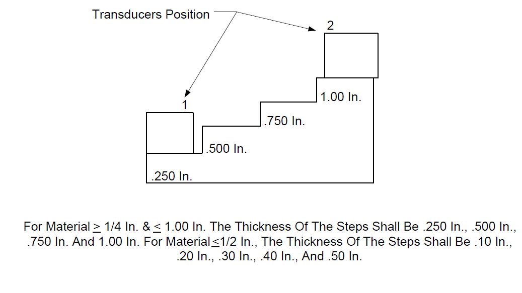
FIGURE 2 IIW OR EQUAL
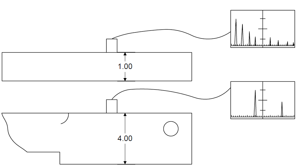
FIGURE 3
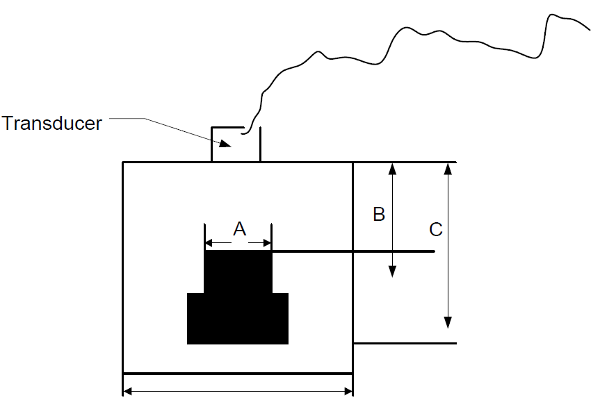
Table 1
| Hole Diameter in 1/64 In. A |
Metal Distance in Inches B |
Overall Length C | Width or Diameter D | Block Identification Number |
|---|---|---|---|---|
| 16 | 1 | 1 3/4 | 2 | 16-0100 |
| 16 | 2 | 2 3/4 | 2 | 16-0200 |
| 16 | 3 | 3 3/4 | 2 | 16-0300 |
| 16 | 6 | 6 3/4 | 3 | 16-0600 |
| 16 | 10 | 10 3/4 | 4 | 16-1000 |
| 16 | B | B = 3/4 | 5 | 16-0B00B |
© 2026 Inflection Point Engineering, LLC. All rights reserved. The content of this page — including calculation methods, reference data, written analysis, interactive tools, and source code — is the intellectual property of Inflection Point Engineering, LLC and is protected under applicable copyright, trademark, and trade secret laws. Unauthorized reproduction, redistribution, modification, or derivative use in whole or in part is prohibited without prior written consent.
Disclaimer. This material is provided for informational and educational purposes only and does not constitute professional engineering advice. Calculations, reference data, and methodologies are based on published standards and accepted engineering practice but are not a substitute for engineering judgment, site-specific analysis, or review by a licensed Professional Engineer. Inflection Point Engineering, LLC makes no warranties, express or implied, regarding the accuracy, completeness, or fitness for a particular purpose of any content presented here, and shall not be liable for any direct, indirect, incidental, or consequential damages arising from its use. Users assume all risk associated with applying this content to real-world design, operations, or decisions.
© 2026 Inflection Point Engineering, LLC. All rights reserved.