 Section 15 — Inspection
Magnetic Particle Examination
IPE Engineering Practice IPE-EP-15-2-4
Document number: IPE-EP-15-2-4 · Section: 15 — Inspection
SCOPE
- This practice covers the minimum requirements to perform and monitor the magnetic particle inspection method by Inflection Point Engineering, LLC Inspectors and contractors using A.C. and D.C. Yokes to examine plant weldments.
- Inspection contractors, whose Magnetic Particle procedures have been submitted and approved by Inflection Point Engineering, LLC Company Inspection personnel may perform Magnetic Particle Inspections.
- Any deviation to this practice shall be approved by the procedure described in EP 1–1–3.
- An asterisk ( * ) indicates that a decision by the Owner’s Level III or Inspection Authority is required or that additional information is furnished by the Purchaser.
2.0 REFERENCES
The latest edition of the following standards and publications are referred to herein.
STANDARDS AND PUBLICATIONS
| IPE Engineering Practices |
|---|
| EP 1–1–3 Deviations to IPE Engineering Practices EP 15–3–2 Training, Qualifying and Certifying Personnel for NDE of Plant Equipment |
| ASME Codes |
| Sec V Non–Destructive Examination |
| ASNT |
| TC–1A Certification of NDE Personnel |
| ASTM Codes |
| E-165 Standard Test Method for Liquid Penetrant Examination E-709 Standard Guide for Magnetic Particle Examination |
DEFINITIONS
- Black Light – Black light as specified herein shall be applied to the invisible radiant energy in that portion of the spectrum just beyond the blue of the visible spectrum and shall have wave length of between 3,300 and 3,900 angstrom units.
- Fluorescence – A term used to describe the effects produced by certain chemical products which exhibit a property of emitting visible light by the activation of black light. These materials absorb the invisible energy, alter its wavelength, and emit the energy in the form of light which is visible to the eye.
- Continuous Method - Applying the dry particles / bath to the inspection surface while the part is under influence of the magnetic field.
- Longitudinal Magnetization - An electric current is passed through a multi–turn coil (either yoke, ridged or cable formed) which encloses the part or section of the art to be examined. The induced field will be parallel with the axis of the coil.
- Circular Magnetization - An electric current is passed through a part or by use of a central conductor through a central opening in the part, inducing a magnetic field at right angles to the current flow.
- Magnetic Field Indicator - Is used as a convenient rough check of the adequacy and direction of part magnetization.
- Particle Agglomeration - The dry powder gathers into a mass or ball due to contact with moisture.
- Gauss Meter - Is used to verify the residual magnetic field prior to or after magnetic particle inspections.
- Owner - Inflection Point Engineering, LLC.
- Purchaser - The party placing a direct purchase order. The purchaser is the Owner’s designated representative.
- Plant Inspection Authority - That person or body appointed by Management to be responsible for examination and certification of equipment utilized within the plant. Management may appoint more than one Inspection Authority in order to cover specialized equipment such as rotating, instrumentation and electrical equipment.
DESCRIPTION OF METHOD
- For the purpose of this procedure, Visible or Fluorescent Magnetic Particle method may be used with continuous AC/DC/DCHW Longitudinal Yokes.
RESPONSIBILITY
- The Level III shall be responsible for the content of this procedure and subsequent revisions.
- The Inspection Authority shall be responsible to assure that only certified personnel perform these examinations.
CERTIFICATION
- Personnel performing examinations to this procedure shall be certified to the requirements of EP 15–3–2 or an approved contractors written practice.
- This procedure or an approved contractor’s procedure shall be available on–site during these examinations.
SAFETY
- Electrical Arc - Arc causes sparks which may result in fire.
- Prior to using, check to insure the lens on the black light is not cracked or damaged. Inspectors should never look directly into the black light.
- Solvents or baths should not be used near open flames or arc welding operations.
- Cleaners shall be used cautiously.
- Some are highly volatile and flammable and their vapors are relatively toxic.
- Good ventilation shall be maintained at all times.
- Some cleaning solutions are primary skin irritants and prolonged contact with the liquid should be avoided.
- Rubber gloves must be worn in cases of repeated exposure or prolonged contact with cleaners or other wet magnetic particle solutions.
- The hands should be washed thoroughly after contact with any of the liquids.
- The Material Safety Data Sheets and Product Data Sheets shall be read and understood by the inspector prior to using magnetic particle materials .
- When using magnetic particle equipment for examinations, or other AC power lighting equipment, the inspector should take care to avoid electrical shock. Ground fault circuit breakers should always be used along with explosion proof connections, where required, in operating facilities. Worn electrical cords and other equipment should be discarded.
- Ground fault circuit breakers shall always be located outside of confined spaces.
- All applicable plant safety rules shall be followed when performing testing.
SURFACE PREPARATION
- In general, satisfactory results may be obtained when the surface is in the as–welded, as-rolled, as-cast, or as-forged condition, however, surface preparation by grinding may be necessary in some instances where surface irregularities could otherwise mask indications of unacceptable discontinuities.
- Prior to Magnetic Particle examination, the surface to be examined and all adjacent areas within at least 1 inch shall be dry and free of any dirt, grease, lint, scale, welding flux, weld spatter, oil or other extraneous matter that could obscure surface openings or otherwise interfere with the examination.
- Cleaning of the examination surface may be accomplished by detergents, organic solvents or mechanical means.
- Drying, after cleaning of the surface to be examined, shall be accomplished by normal evaporation or with forced hot air, as appropriate.
- Dry Magnetic Particle examination shall not be done on the surface of welds whose temperature exceeds 600oF (316oC).
- Wet Magnetic Particle examinations shall not be done on the surface of welds whose temperature exceeds 135oF (56oC).
- (*) Blasting with shot or dull sand may peen discontinuities at the surface and shall not be used without subsequent etching of the test surface to re–open closed discontinuities. The method for etching and neutralizing shall be approved by the Inspection Authority.
EQUIPMENT
- Yokes shall be capable of delivering currents producing magnetic fields as required in sections 10, 12, 13, and 14 of this practice.
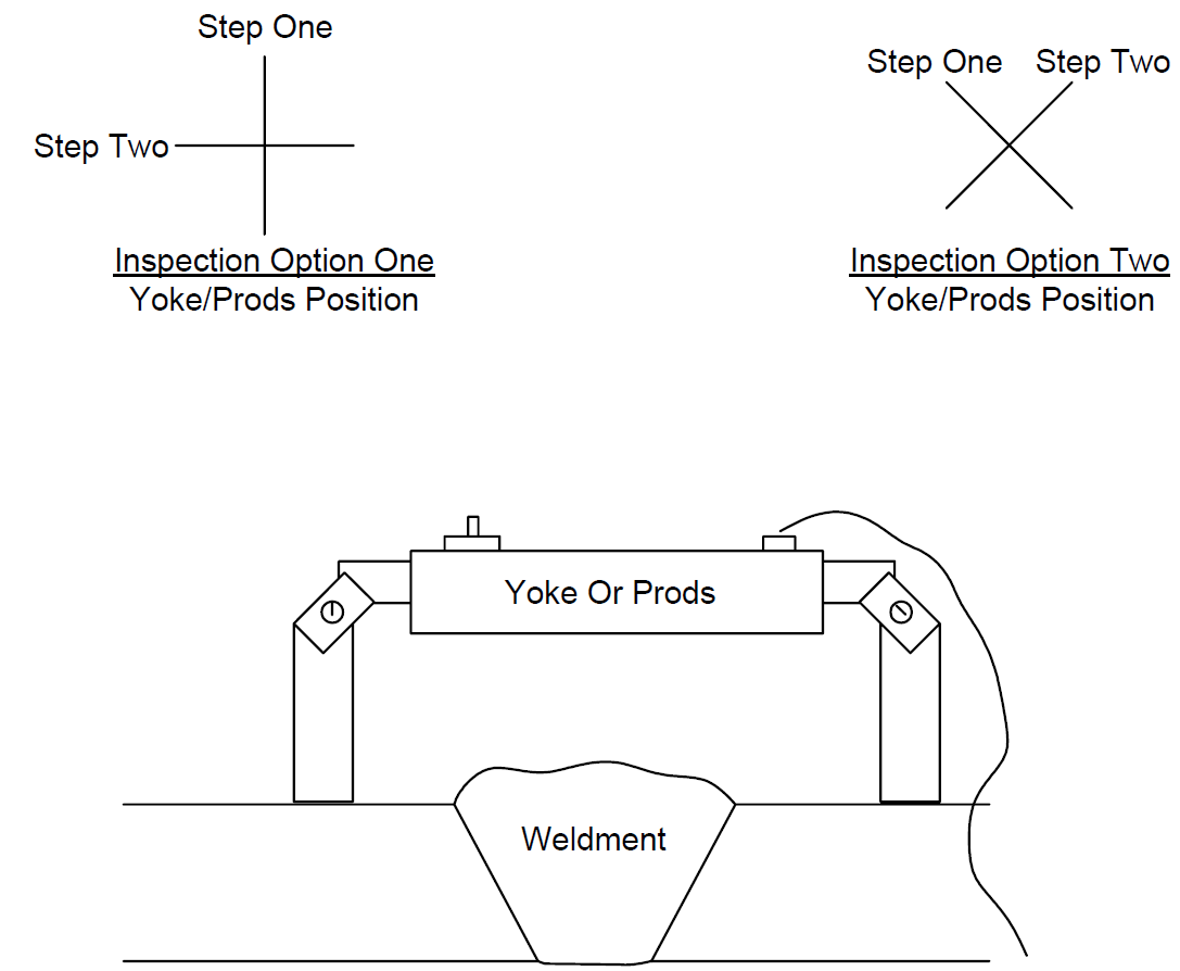
- Yokes are electromagnetic which induce a magnetic field between the legs and are used for local magnetization (Figure 1). Yokes may have fixed legs or articulated legs that can be adjusted to accommodate irregular or angular surfaces.
- Yokes may be fixed AC or DC or AC/DC selectable.
- Magnetic particles/ baths meeting the requirements of ASTM -709 shall be acceptable.
EQUIPMENT CALIBRATIONS
- Yokes do not require periodic calibration.
- The magnetizing force of yokes shall be checked every 6 months, or whenever a yoke has been damaged or repaired by determining their minimum lifting power. These test shall be performed using a certified test block per the applicable code or standard. The minimum test block weight for A.C. (alternating current) 10 lbs. and for D.C./D.C.H.W (direct current) 40 lbs. at the maximum pole spacing.
- The test lift required in 10.2 shall be performed whenever the technician or inspector suspects there may be a problem with the yoke.
GENERAL EXAMINATION REQUIREMENTS
- Magnetic Particle Yokes capable of producing alternating current (A.C.) current or direct current (D.C.) and direct current half wave (D.C.H.W.) in sufficient amperes for the method used are acceptable.
- At the beginning of each inspection or different group of parts to be inspected, and at least once daily, a field indicator shall be used to determine the direction and approximate strength of the magnetic field.
YOKE TECHNIQUE
- This method should be used only to detect discontinuities which actually come to the surface.
- The minimum leg spacing shall be 3”; the maximum pole spacing shall be 6”.
- The magnetic yoke (field) shall be introduced in a minimum of two directions 90 degrees to each other (See Figure 1).
- Overlapping spacing shall be used to make sure complete coverage of the weld is obtained.
- The magnetizing current shot shall be held a minimum of 3 seconds to excite the magnetic particles in the bath or to attract the dry powder when applied.
DRY INSPECTION MEDIUM APPLICATION AND REMOVAL
- Application and Removal – The dry powder shall be applied by lightly dusting a small quantity over the surface and then removing the excess with a gentle air stream. The air stream shall be controlled so that it does not disturb or remove the lightly held powder patterns.
- Dry powder shall be applied and the excess particles removed during the current shot– continuous.
- Color contrasting dry powders shall be used.
WET INSPECTION MEDIUM APPLICATION AND REMOVAL
- Apply the bath to the surfaces of the weld. The instant the bath stream is removed from the weld, apply the magnetizing current. The indications will be formed during the current shot.
Do not apply the baths after the magnetizing shot; the force of the bath application may wash away indications.
- The bath must be continuously agitated when in use to insure uniformity; particles will settle out of suspension on standing.
- The bath strength shall be checked at make-up time and at least once daily using a 100 ml Centrifuge tube settling test and shall be per the manufacturers data sheet for this test.
LIGHTING
- Visible Light
The intensity of the light at the surface of the part/work piece undergoing examination should be a minimum of 100-foot candles. A two-cell flash light (“D” batteries) with reasonably fresh batteries will emit 150fc @ 12”.
- Black Light
- The examination shall be performed in a darkened area of not more than 2 foot–candles.
- The technician shall be in a darkened area for at least 5 minutes prior to performing the examination to enable his eyes to adapt to dark viewing. If the technician wears glasses or lenses, they shall not be photosensitive.
- The black light shall be allowed to warm up for a minimum of 5 minutes prior to use or measurement of the intensity of the ultraviolet light emitted.
- The black light intensity shall be measured with a calibrated black light meter. A minimum of 1000 (w/cm2 on the surface of the part being examined shall be required. The black light intensity shall be measured prior to use, at least once every 8 hours, and whenever the work station is changed.
EVALUATION OF INDICATIONS / DOCUMENTATION
- Mechanical discontinuities at the surface will be indicated by the retention of the examination medium. All indications are not necessarily defects or discontinuities, since certain metallurgical discontinuities and magnetic permeability variations may produce similar indications which are not relevant to the detection of unacceptable discontinuities.
- Non–relevant Indications – Any indication which is believed to be non–relevant shall be regarded as a defect and shall be re–examined to verify whether or not actual defects are present. Surface conditioning may precede the examination. Non–relevant indications which would mask indications of defects are unacceptable. Other NDE methods( i.e. penetrant) may be used to verify these indications.
- Relevant Indications – Relevant indications are those which result from mechanical discontinuities. Linear indications are those indications in which the length is more than three times the width. Rounded indications are indications which are circular or elliptical with the length less than three times the width.
- Acceptance Criteria – For determination of the appropriate criteria, the inspector shall review the required engineering documentation, code/standard or EP.
- (*) Documentation – Table 1 – A Magnetic Particle Inspection Report, shall be completed for every code examination performed by Inflection Point Engineering, LLC Inspectors. NDT Contractors may use forms that were approved with their procedures.Table 1
DISPOSAL OF MAGNETIC PARTICLE MATERIALS
- Empty spray cans of magnetic particle suspension bath must be properly disposed of in accordance with plant requirements.
- Used or unused mixed magnetic particle baths must be properly disposed of in accordance with plant requirements.
18.0 TABLES
TABLE 1
INFLECTION POINT ENGINEERING, LLC
MAGNETIC PARTICLE INSPECTION REPORT
| LOCATION | LOCATION | LOCATION | LOCATION |
|---|---|---|---|
| UNIT | UNIT | PROCEDURE NO. | PROCEDURE NO. |
| COMPONENT | COMPONENT | CODE OR STANDARD | CODE OR STANDARD |
| WELD DESCRIPTION | WELD DESCRIPTION | SEE SKETCH NUMBER | SEE SKETCH NUMBER |
| M/T EQUIPMENT | PARTICLE/BATHS | PARTICLE/BATHS | METHOD |
| SERIAL NUMBER | COLOR | COLOR | CONTINUOUS |
| MAKE MODEL | WET DRY |
WET DRY |
LONGITUDINAL CIRCULAR |
| YOKE AC DC OTHER |
VISUAL FLUORESCENT MANUFACTURER |
VISUAL FLUORESCENT MANUFACTURER |
|
| DATE OF UNIT RE- CALIBRATION | DATE OF UNIT RE- CALIBRATION | LIFT TEST WEIGHT 10LBS 40 LBS. |
| WELD NO. | LOCATION | LOCATION | ACC. | REJ. | REJ. | COMMENTS |
|---|---|---|---|---|---|---|
| LOCATION | LOCATION | LEVEL | LEVEL | LEVEL | DATE | DATE |
| NAME | NAME |
19.0 FIGURES
FIGURE 1
INSPECTION TECHNIQUES FOR PRODS AND YOKES
© 2026 Inflection Point Engineering, LLC. All rights reserved. The content of this page — including calculation methods, reference data, written analysis, interactive tools, and source code — is the intellectual property of Inflection Point Engineering, LLC and is protected under applicable copyright, trademark, and trade secret laws. Unauthorized reproduction, redistribution, modification, or derivative use in whole or in part is prohibited without prior written consent.
Disclaimer. This material is provided for informational and educational purposes only and does not constitute professional engineering advice. Calculations, reference data, and methodologies are based on published standards and accepted engineering practice but are not a substitute for engineering judgment, site-specific analysis, or review by a licensed Professional Engineer. Inflection Point Engineering, LLC makes no warranties, express or implied, regarding the accuracy, completeness, or fitness for a particular purpose of any content presented here, and shall not be liable for any direct, indirect, incidental, or consequential damages arising from its use. Users assume all risk associated with applying this content to real-world design, operations, or decisions.
© 2026 Inflection Point Engineering, LLC. All rights reserved.