 Section 15 — Inspection
Color Coding for Material Identification
IPE Engineering Practice IPE-EP-15-1-5
Document number: IPE-EP-15-1-5 · Section: 15 — Inspection
SCOPE
- This Practice covers the mandatory requirements for marking materials normally used at Owner’s Plant to permit Positive Material Identification (PMI) in the storehouse, shop, and field.
- The color coding system described in this Practice is intended to help prevent corrosion and premature service failures as a result of using the incorrect material. Accordingly, those materials identified in Table 1 and Table 2 of this Practice for each of the Plant locations shall be color coded.
- The color coding portion of this standard does not apply to:
- Miscellaneous machinery repair parts.
- Materials not covered by paragraph 4.7 of this Practice.
- Any deviation from this Practice must be approved by the procedure described in EP 1–1–3.
- A revision bar indicates all changes made to this Revision.
2.0 REFERENCES
The latest edition of the following standards and publications are referred to herein.
STANDARDS AND PUBLICATIONS
DEFINITIONS
- Manufacturer - The recipient of a direct or indirect purchase order for materials and/or equipment. In this context, a direct order is one issued to a manufacturer by a contractor or the Owner. An indirect order is one issued to a manufacturer by a vendor (recipient of a direct order) for materials, fabricated components, or subassemblies.
- Owner - Inflection Point Engineering, LLC.
- Owner’s Engineer - A Inflection Point Engineering, LLC appointed engineer.
MATERIAL MARKINGS REQUIREMENTS
- The marking requirements described in this Practice shall be applied by the Manufacturer (supplier or vendor as applicable) and are supplemental to the markings required by the ASTM, API, ANSI, MSS, and other specifications under which the materials are manufactured. Therefore, upon delivery to the Plant stores, each piece of material can have up to three types of markings:
- Mechanically applied characters (stamped) indicating material type symbol per the applicable standard.
- Painted characters indicating material type symbol.
- (*)A Painted Color Code per this Practice. Unless otherwise indicated in the purchase order, the Manufacturer shall apply this color code.
- The color markings are assigned on the basis of material composition. Identification by this method is not a substitute for other permanent Manufacturers’ markings required by applicable ASTM or other materials specifications. None of the Manufacturers’ markings should be obscured by color coding. The principal purpose of the method is to insure identification during storage and after the material has been cut for fabrication. This includes material returned to stock.
- Positive Materials Identification (PMI) shall be performed in accordance with EP 15–1–4 on all materials which are to be color coded per the requirements of this Practice.
- Color coding need not be retained when painting is done after completion of fabrication.
- Paints used for identification shall be durable and of distinctive identifying colors. Marking shall be done with a marker equal to Metal Marker, as manufactured by the John P. Nissen, Jr., Company, Glenside, Pennsylvania. Paints containing sulfur, lead, or other metals are not acceptable.
- Surfaces to be color coded shall be cleaned and free of dirt, loose scale, and oil.
- The color code shown in Table 1 shall be used for marking material. Application of the required material markings shall be in accordance with Table 1.
5.0 TABLES
TABLE 1
COLOR CODE FOR MATERIAL IDENTIFICATION
| COLOR | SINGLE SOLID STRIPE | SINGLE DASHED STRIPE | DOUBLE SOLID STRIPE |
|---|---|---|---|
| None | General Service Pipe (Carbon Steel) per EP 5–2–1 Carbon Steel, A193 Gr B7 Studs Aluminum All Grades |
— | — |
| Yellow | Carbon Steel for Low Temperature Service (Below –20F), A 320 Gr L7 Studs |
Restricted Service Pipe (Carbon Steel) per EP 5–2–1 | Type 304 (18 Cr–8 Ni) |
| White | RA 330 (19 Cr–35 Ni– 1–1/4Si) |
Type 310 (25 Cr - 20 Ni) |
Type 316 (16 Cr–12 Ni–2 Mo) |
| Red | AISI 4140 Steel Alloy 20 (20 Cr - 29 Ni) |
Carpenter 20 Cb–3 (33 Ni–20 Cr) |
Type 321 (18 Cr–10 Ni–T) |
| Gray | 1–1/4 Cr– 1/2 Mo Steel, A193 Gr B–16 Studs | EBRITE (26 Cr - 1 Mo) | Type 347 (18Cr– 10Ni–Cb) |
| Orange | 2–1/4 Cr–1 Mo Steel | Duplex 2205 (22 Cr–5 Ni–3Mo) |
Incoloy 800 (20 Cr–32 Ni) |
| Green | 5 Cr– 1/2 Mo Steel | 7 Cr - 1/2 Mo Steel | Type 304L, Low Carbon (18 Cr–8 Ni) |
| Purple | 9 Cr–1 Mo Steel | — | Type 316L, Low Carbon (16 Cr–10 Ni–3 Mo) |
| Black | 12 Cr–1 Mo Steel, Type 405, 410, 410S | — | Hastelloy “B” (65 Ni - 30 Mo) |
| Pink | 17 Cr Steel, Type 430 | Inconel 625 (60 Ni–20Cr - 10 Mo) |
Inconel 600 (72 Ni - 15Cr) |
| Blue | 3–1/2 Ni Steel | — | Monel 400 (67 Ni - 30 Cu) |
| Brown | Ductile, Nodular Iron | — | Hastelloy “C” (60 Ni–15Cr–17Mo) |
TABLE 2
APPLICATION OF MATERIAL MARKING
| MATERIAL COMPONENTS | MARKING APPLICATION |
|---|---|
| Pipe, Fittings, Shapes, Tube and Bar | Stripe entire length as shown in Figure 1. Boxes or bundles of tubing or bar 1– inch or smaller may be color coded by striping the box or binding straps. |
| Flanges | Stripe across edge up to hub as shown in Figure 2. |
| Plate, Sheet, and Strip | Stripe along any two edges or on surface near edge for entire length as shown in Figure 3. |
| Valves | Stripe across body from flange to flange as shown in Figure 4. |
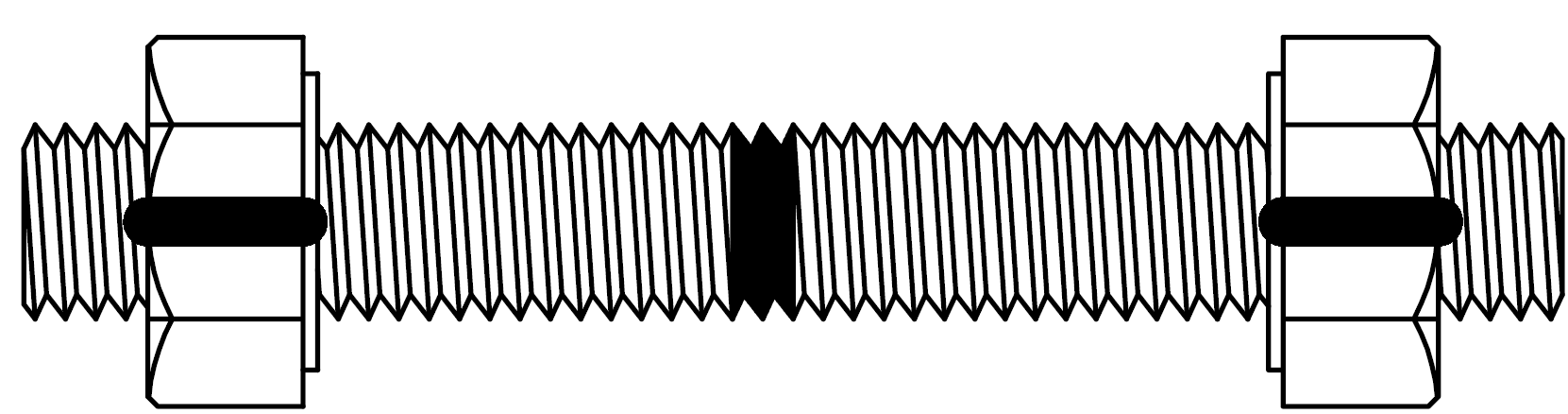
| Bolting Materials | Stamped per requirements of EP 5–2–2: Bolts and Studs on end, and nuts on one flat. If not, Bolts and Studs must be striped as shown in Figure 5. |
6.0 FIGURES
FIGURE 1
MATERIAL MARKINGS FOR PIPE FITTINGS


FIGURE 2
MATERIAL MARKINGS FOR FLANGES
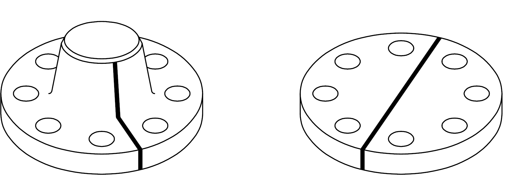
FIGURE 3
MATERIAL MARKINGS FOR PLATE
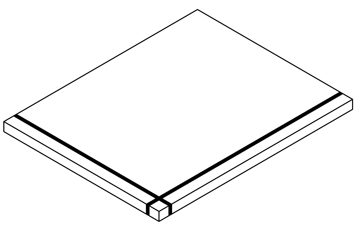
FIGURE 4
MATERIAL MARKINGS FOR VALVES
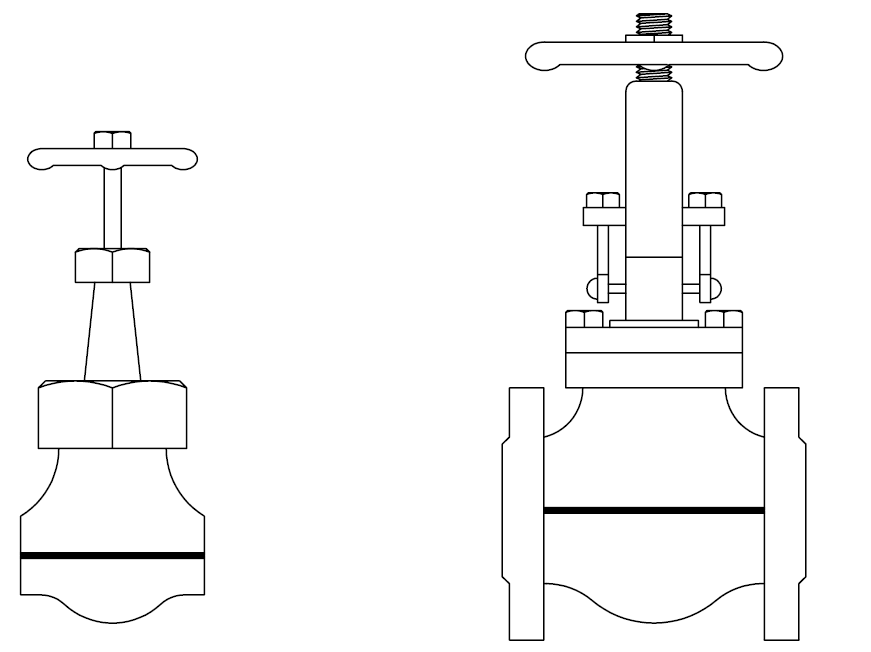
FIGURE 5
MATERIAL MARKINGS FOR BOLTS
© 2026 Inflection Point Engineering, LLC. All rights reserved. The content of this page — including calculation methods, reference data, written analysis, interactive tools, and source code — is the intellectual property of Inflection Point Engineering, LLC and is protected under applicable copyright, trademark, and trade secret laws. Unauthorized reproduction, redistribution, modification, or derivative use in whole or in part is prohibited without prior written consent.
Disclaimer. This material is provided for informational and educational purposes only and does not constitute professional engineering advice. Calculations, reference data, and methodologies are based on published standards and accepted engineering practice but are not a substitute for engineering judgment, site-specific analysis, or review by a licensed Professional Engineer. Inflection Point Engineering, LLC makes no warranties, express or implied, regarding the accuracy, completeness, or fitness for a particular purpose of any content presented here, and shall not be liable for any direct, indirect, incidental, or consequential damages arising from its use. Users assume all risk associated with applying this content to real-world design, operations, or decisions.
© 2026 Inflection Point Engineering, LLC. All rights reserved.