 Section 14 — Equipment Protection & Package Units
Pre-commissioning Cleaning of Rotating Equipment,
IPE Engineering Practice IPE-EP-14-1-4
Document number: IPE-EP-14-1-4 · Section: 14 — Equipment Protection & Package Units
SCOPE
- This Practice covers the minimum mandatory requirements and acceptable procedures for chemical and mechanical precommission cleaning of the following equipment.
- Compressor suction and interstage systems.
- Steam turbine inlet piping.
- Lube and seal oil systems.
- Positive Displacement Pumps.
- Fired and unfired steam generators having steam outlet pressures of 1800 psig and under.
- Post cleaning passivation of metal surfaces to prevent prestart-up contamination is also covered by this Practice.
- This Practice does not cover chemical cleaning of equipment; however, many of the procedures introduced may be used in this function.
- Any deviation from this Practice must be approved by the procedure described in EP 1-1-3.
- An asterisk (*) indicates that additional information is required. If a job is contracted, this information will be furnished by the Purchaser.
2.0 REFERENCES
The latest edition of the following standards and publications are referred to herein.
STANDARDS AND PUBLICATIONS
DEFINITIONS
- Contractor - Company or business that agrees to furnish materials or perform specified services at a specified price and/or rate to the Owner.
- Inspection - An activity to check that design, materials, fabrication, and testing comply with the requirements of the specification.
- Manufacturer - The recipient of a direct or indirect purchase order for materials and/or equipment. In this context, a direct order is one issued to a Manufacturer by a Contractor or the Owner. An indirect order is one issued to a Manufacturer by a vendor (recipient of a direct order) for materials, fabricated components, or subassemblies.
- Owner - Inflection Point Engineering, LLC.
- Owner's Engineer - A Inflection Point Engineering, LLC appointed engineer.
- Purchaser - The party placing a direct purchase order. The Purchaser is the Owner's designated representative.
PROPOSAL INFORMATION
- (*) A specification describing the services, equipment and procedures proposed shall be furnished to the Purchaser for approval by the Owner's Engineer.
- Services proposed by the cleaning Contractor shall not include operating functions on the Owner's equipment or facilities.
- Alternatives to the acceptable procedures for Alkaline Detergent Wash or Solvent Cleaning presented herein shall be accompanied by a detailed description of the procedures proposed, including:
- Schematic drawings of the cleaning circuits to be used. Drawings shall indicate size and type of all cleaning connections, and location of post cleaning inspection points.
- Chemicals to be used and method of introduction. An MSDS report report for all proposed chemicals shall be submitted.
- Concentrations, temperatures, circulation rates and contact times (minimum, maximum, and working level) of chemical solutions to be used.
- Details of inhibitors to be used, effectiveness of inhibitors against corrosion and sampling and testing schedule.
DOCUMENTATION REQUIREMENTS
- The cleaning Contractor shall prepare and maintain a continuous log of the cleaning operation, recording all aspects, including:
- Chemicals used and the amount used.
- Temperatures, concentrations, and circulation rate of cleaning solutions.
- Test results.
- Contractor shall submit a drain sample(s) to Owner for analysis of iron content.
- (*) A copy of the log shall be submitted to the Purchaser for review with the Owner's Engineer on completion of each cleaning operation.
RESTRICTIONS AND PRECAUTIONS DURING CLEANING
- General
- Equipment containing austenitic materials shall not be contacted with:
- Acid solutions containing halides, and chemicals such as hydrochloric acid. Alternative solvents are acceptable provided the diluted chloride content does not exceed 25 ppm.
- Caustic soda (NaOH) solutions.
- If degreasing is required, Sodium Carbonate and Trisodium Phosphate solution may be used provided the chloride content does not exceed 100 ppm.
- Rinse water that is not clean or exceeds 100 ppm chloride.
- Chemical solutions shall not be introduced into equipment unless high point vents and low point drains are available to insure proper filling and complete removal of solutions.
- (*) Proper disposal of cleaning solutions, and venting, shall be agreed upon by the Owner and Contractor.
- Heat shall not be applied directly to equipment containing acid solutions. Boilers may be fired for degreasing, but acid solutions must be diluted and heated externally to the equipment.
Additional Requirements for Steam Generators
- All chemical treatments shall be reviewed and approved by the equipment Manufacturer prior to start of the cleaning operation.
- Concentrated acid shall not be added to the steam drum of a hot boiler. However, the addition of chelating agents is acceptable.
- Superheaters shall be positively back flushed and flooded with condensate or demineralized water during acid cleaning.
- The Contractor's drain hose or piping shall be sized to permit complete draining of the equipment in two hours or less.
- In boilers that cannot adequately be circulated, solution movement can be provided by raising and lowering levels to provide solution displacement in tubes. An alternative is bubbling with nitrogen to create agitation if raising and lowering solution levels is impractical.
INSPECTION AND TESTING
During Cleaning
- A test shall be conducted during the filling of the equipment to make certain that acid is properly inhibited. A sample of circulating fluid shall be retained for test purposes. One acceptable test involves heating the inhibited solution to 170°F into which a de-greased coupon, approximate size 1 x 1 x 1/8 inches is placed. Inhibitor present is satisfactory if no continuous stream of hydrogen bubbles is observed after 30 seconds.
- During cleaning with hydrochloric acid the solution shall be analyzed at least once per hour for ferric iron and total iron. Ferric iron content greater than 0.4 percent and/or total iron content greater than 1.5 percent, with an increasing slope on the curve when iron is plotted versus time, indicate excessive corrosion and solutions should be dumped as fast as possible.
- Carbon steel test pieces shall be exposed in the steam drum during acid cleaning using pre- measured and pre-weighed test coupons 1 x 1 x 1/8 inches to obtain actual corrosion rate. Corrosion rate shall be less than 0.02 mils per hour.
After Cleaning
- To assess that the necessary degree of cleaning required has been achieved, inspection is required at the following locations.
- Steam generation section:
- All boiler headers.
- Boiler drums, including tube ends.
- Piping systems:
- Pipework where accessible, e.g., where broken for discharge or steam blowing.
- Pipe work where broken for temporary connections.
- Removal of solids shall be confirmed by the use of target plates during steam blowing.
- A gas test is required before any hot work can be performed.
8.0 CLEANING REQUIREMENTS FOR ROTATING EQUIPMENT
The degree of cleaning and surface preparation required, and acceptable methods to accomplish this are specified in Table 1 for rotating equipment piping systems.
9.0 CLEANING REQUIREMENTS FOR STEAM GENERATING EQUIPMENT
The degree of cleaning and surface preparation required, and the acceptable method to accomplish this are specified in Table 2 for steam generating equipment.
10.0 TABLES
TABLE 1
DEGREE OF CLEANING AND SURFACE PREPARATION FOR ROTATING
| Equipment Type (1) | Degree of Cleaning And Surface Preparation Class (2) |
Acceptable Methods (3) |
|---|---|---|
| Lube and Seal Oil Systems (field fabricating piping only) |
I, II, III, IV | 3, 4, 5, 6 |
| Centrifugal and Axial Compressor Suction | I | 2 |
| Reciprocating and Rotary Compressor Suction and Interstage (including vessels, exchangers and pulsation bottles) |
I,II,III,IV | 1 or 2, 7; or 3, 4, 5, 6 |
| Positive displacement; Pumps Suction | I, II, III, IV | 3, 4, 5, 6 |
| Steam Turbine Inlet: >625 psig | I, II, III, IV | 3, 4, 5, 6 |
| Steam Turbine Inlet: □ 625 psig | l | 8 |
NOTES:
- Pertain to piping systems fabricated from carbon and low alloy steel (P-1, P-2, P-3, P-1, and P-5).
- See Table 3 for Class Description.
- See Table 4 for cleaning step description; cleaning step procedure shall be followed In the order as shown in this table.
TABLE 2
DEGREE OF CLEANING AND SURFACE PREPARATION FOR STEAM GENERATING EQUIPMENT
| Equipment Type (1) | Steam Outlet Pressure (psig) | Degree of Cleaning and Surface Preparation Class (2) |
Acceptable Cleaning Method (3) |
|---|---|---|---|
| Feed Water Line Downstream of Dearerator |
< 450 | l | 3 |
| 450 -1800 | I, II, III, IV | 3, 4, 5, 6 | |
| Steam Generator | < 450 | I, II | 3, 4 |
| 450 -1800 | I, II, III, IV | 3, 4, 5, 6 | |
| Superheater, Drainable and Ventable |
<450 | I, II | 1, 3, or 3, 4 |
| 450 -1800 | I, II, III, IV | 3, 4, 5, 6 or 1, 3, 8 |
|
| Superheater, Non- Drainable and Non- Ventable | < 450 | I, II | 1, 3, 8 |
| 450 - 1800 | I, II, III | 1, 3, 8 |
NOTES:
- Pertains to piping systems fabricated from carbon and low alloy steel (P-1, P-2, P-3, P-4, and P-5).
- See Table 3 for Class Description.
- See Table 4 for cleaning step description; cleaning step procedures shall be followed in the order as shown in this table.
TABLE 3
CLEANING STEP DESCRIPTION
| STEP | CLEANING STEP DESCRIPTION |
|---|---|
| 1 | Clean Construction Techniques: For compressor and positive displacement pump piping prior to fabrication; sand or grit blasting for rust and scale removal together with "clean" weld techniques (TIG, MIG, etc.) for all closing welds. For steam generators this includes the use of cold drawn tubing and cold bending. |
| 2 | Post Fabrication Mechanical Cleaning: Grinding, pigging, or sand or grit blasting. |
| 3 | Flushing with fresh clean water to remove trash and debris. |
| 4 | Alkaline detergent wash for oil and grease removal, see Table 5 of this Practice. |
| 5 | Solvent cleaning with acids or chelants, for rust and mill scale removal. See Table 6 for Piping Systems (hydrochloric acid) and Table 7 for Steam Generating Equipment (hydrochloric acid, citric acid, or chelants). |
| 6 | Post Cleaning Passivation: Prevention of after-rusting of cleaned surfaces by chemical treatment, see Table 8. |
| 7 | Post Cleaning Protection: Vapor phase inhibitor such as Cortec VCl 560 or coating with a lubricant compatible rust preventive except for non-lubricated compressors and those in refrigeration service. Blind, plug, or cap all piping joints left temporarily disconnected. |
| 8 | Steam blow to ensure removal of loose scale. |
TABLE 4
CLASS DESCRIPTIONS FOR CLEANING AND SURFACE PREPARATION
| CLASS | DESCRIPTION |
|---|---|
| l | Removal of all loose non-adherent materials together with all adherent material which could break away during operation of the equipment |
| II | Removal of oil, grease, and protective coatings. |
| III | Removal of adherent rust and mill scale to leave bare metal. |
| IV | Protection of surface to prevent rust bloom following cleaning and prior to startup. |
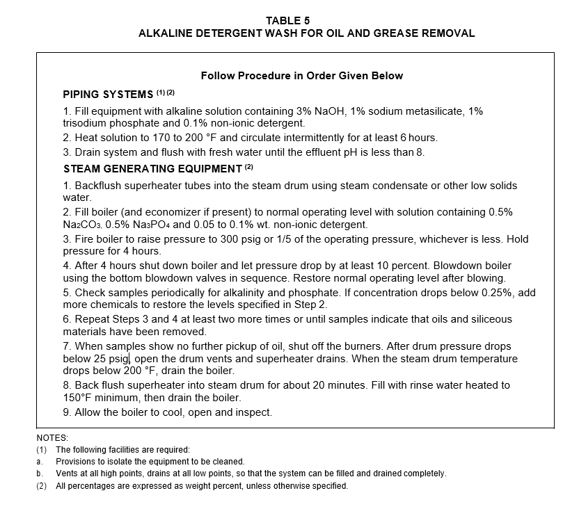
TABLE 6
SOLVENT CLEANING FOR RUST AND MILL SCALE REMOVAL FROM PIPING SYSTEM (3)
NOTES:
- Use of Inhibited hydrochloric acid is acceptable for carbon and low alloy steels. It is not acceptable for systems containing stainless or high alloy steels.
- The following facilities are required:
- Provisions to isolate the equipment to be cleaned.
- Vents at all high points, drains at all low points, so that the system can be filled and drained completely.
- (*) Where piping systems can be readily cleaned by vapor phase techniques, or with chelants, proposals to use such methods shall be submitted to purchaser for approval by Owner's Engineer.
All percentages are expressed as weight percent, unless otherwise specified
TABLE 7
SOLVENT CLEANING FOR RUST AND MILL SCALE REMOVAL
Follow Procedure in Order Given Below INHIBITED HYDROCHLORIC ACID (1)(2)(4)
- Fill the superheaters and economizers with condensate or other low solids water, and maintain
water "wedge" during remainder of cleaning operation.
- Fill the boiler with water heated to 180 °F or alternatively fill the boiler with water and inject steam to bring temperature to 180 °F. When metal temperatures have reached 180 °F, drain the boiler. Close all furnace openings and dampers to retain heat.
- Open the drum vent valves. Close the boiler blowdown and chemical valves. Isolate all other valves not being used for circulation.
- a. Fill the boiler to the normal liquid level with 6 percent inhibited hydrochloric acid solution containing 0.25% by wt. ammonium bifluoride heated to 160 °F maximum by blending the dilution water with steam. Inhibitor shall be Armohib 28, Rodine 213, or equivalent in concentrations of 2 gal per 1000 gal of boiler capacity (Inhibitor effectiveness should be confirmed by test).
b. Alternatively, hot water may be withdrawn form the boiler, pumped through a mixing header to provide no more than 10 percent concentration and returned to the steam drum. In this case, it is recommended that at least half of the required inhibitor shall be added to the water prior to acid injection.
- The solution shall be circulated for 15 minutes each hour for at least four hours. Samples shall be taken each hour following circulation and tested for acid strength and total iron concentration. Cleaning is continued until acid strength and total iron concentration reach equilibrium. If acid concentration drops below 3% add additional acid to bring concentration up to 5%.
- Drain the acid solution under nitrogen pressure.
- Fill the drum to high water level with water heated to 150°F. Simultaneously back flush the superheater with condensate or low solids water into the steam drum. Drain the boiler.
- Refill the boiler with clear water containing 0.1% citric acid at 150°F. Circulate for 1 hour. Drain under nitrogen pressure.
- Fill the boiler to normal operating level with a neutralizing solution containing 1% by wt. soda ash (Na2 CO3 ). Fire the boiler and bring the pressure to 100 psig and hold for 2 hours. Allow the boiler to cool to less than 200 °F, then drain.
- Allow the boiler to cool, open and inspect.
TABLE 7 (CONT,)
SOLVENT CLEANING FOR RUST AND MILL SCALE REMOVAL FROM STEAM GENERATING EQUIPMENT
TABLE 7 (CONT.)
SOLVENT CLEANING FOR RUST AND MILL SCALE REMOVAL FROM STEAM GENERATION EQUIPMENT
CHELATING AGENTS (4)(5)
- Fill the boiler and fire to bring the temperature to about 250 °F. Drop the level in the steam drum to make room for cleaning solvent.
- Dilute sufficient inhibitor (Dow-A-196 or Haliburton OSI-1) with water to make a 0.1% solution in the boiler, and add to the boiler via the chemical addition line. Wait 30 minutes for thermal mixing.
- Pump in sufficient chelant to make a minimum 4% chelant concentration (10% max.) by wt. in the boiler. Adjust level in the boiler to normal level.
- Isolate the system, but make certain the superheater is protected by venting to avoid overheating of tubes (NOTE: Vapor will contain noxious ammonia fumes).
- Fire the boiler to raise the pressure to 80 psig (Temperature not to exceed 325 °F. Stop firing, leave fans on at low speed, and allow the pressure to drop to 20 psig.
- Sample and titrate at least once per hour for available chelant and for iron.
- Repeat Step 5 until the concentration of chelant and iron stabilize. If chelant concentration drops below 1% add sufficient chelant to bring the concentration up to 3%. The job is complete when the titration shows stable chelant concentration with no further increase in iron. The total time required may be 12 to 18 hours. The pH during cleaning should be about 9.2 to 9.5. If the pH drops below 9.0, add ammonia to raise the pH to about 9.2 to 9.5.
- Cool the boiler to less than 200°F and drain under nitrogen pressure.
- Backflush superheater with condensate into the steam drum for 20 minutes to insure removal of any entrained chemical. Fill the boiler to high level with clean water containing 100 ppm hydrazine at 180°F, or passify the cleaned metal surface with another suitable passivation system (such as nitrite or hydroquinone).
- Drain under nitrogen pressure.
- Allow the boiler to cool, open and inspect.
NOTES:
- Use of inhibited hydrochloric acid is acceptable provided the boiler can be properly isolated from instrument leads, etc.
- The following facilities are required:
- A NPS 2 inch or larger acid fill and drain connection to the steam and mud drums.
- Hot water or steam heating line with facility to regulate temperature between 150 and 180°F at location near boiler.
- An atmosphere vent line and a nitrogen fill line on the steam drum.
- Use of Ammoniated Citric acid per the procedure specified in the citrosolve process licensed by Chas. Pfizer & Co. is acceptable.
- Use of chelants of the type represented by the ammonium salt of ethylenediaminetetrascetic acid (Dow Vertan 675 or Halliburton Macor) is acceptable.
- All percentages are expressed as weight percent, unless otherwise specified. General Note: Armohib is a trademark of ARMAK Co.
Macor is a trademark of Halliburton Services
Rodine is a trademark of AMCHEM Products Inc. Vertan is a trademark of Dow Chemical Co.
TABLE 8
POST CLEANING PASSIVATION
NOTES:
- Piping must be flushed free of alkaline deposits and air dried prior to commissioning.
- The following options shall be followed:
- Boiler may be fired as required to prevent freezing.
- Boiler may be started without draining passivation solution, provided steam is vented at the boiler until hydrozine content of boiler water is approximately 1 ppm.
- All percentages are expressed in weight percent, unless otherwise specified.
© 2026 Inflection Point Engineering, LLC. All rights reserved. The content of this page — including calculation methods, reference data, written analysis, interactive tools, and source code — is the intellectual property of Inflection Point Engineering, LLC and is protected under applicable copyright, trademark, and trade secret laws. Unauthorized reproduction, redistribution, modification, or derivative use in whole or in part is prohibited without prior written consent.
Disclaimer. This material is provided for informational and educational purposes only and does not constitute professional engineering advice. Calculations, reference data, and methodologies are based on published standards and accepted engineering practice but are not a substitute for engineering judgment, site-specific analysis, or review by a licensed Professional Engineer. Inflection Point Engineering, LLC makes no warranties, express or implied, regarding the accuracy, completeness, or fitness for a particular purpose of any content presented here, and shall not be liable for any direct, indirect, incidental, or consequential damages arising from its use. Users assume all risk associated with applying this content to real-world design, operations, or decisions.
© 2026 Inflection Point Engineering, LLC. All rights reserved.