 Section 13 — Electrical
480 Volt Prefabricated Switchracks
IPE Engineering Practice IPE-EP-13-7-1
Document number: IPE-EP-13-7-1 · Section: 13 — Electrical
1.0
1.1
1.2
1.3
1.4
2.0
SCOPE
This Practice, including the 480 Volt Prefabricated Switchrack Data Sheet (EP 13–7–1 DS), covers the requirements for pre–fabricated, 600 volt class, 3 phase, 3 wire, 60 Hertz switchracks which will be installed in a petro–chemical plant.
This Practice is appropriate for attachment to an inquiry or purchase document when accompanied by the referenced IPE Engineering Practices and completed Data Sheets.
Any deviation to this Practice must be approved by the procedures described in EP 1–1–3. A revision bar indicates all changes made to this Revision.
REFERENCES
All applicable sections of the latest standards and codes listed below are a part of this Practice. All equipment provided shall be in full compliance with the codes and standards listed below in all matters of construction/fabrication, wiring, testing and listing.
STANDARDS AND PUBLICATIONS
| IPE Engineering Practices |
|---|
| EP 1–1–3 Deviations to IPE Engineering Practices EP 13–7–1 DS 480 Volt Prefabricated Switchracks Data Sheet EP 13–7–2 NEMA 3R, 4X, 4X/7 Combination Motor Starters, Circuit Breaker with Enclosures and Panel Board Assemblies EP 13–7–2 DS NEMA 3R, 4X, 4X/7 Combination Motor Starters, Circuit Breaker with Enclosures and Panel Board Assemblies Data Sheet |
| ANSI |
| C80.1 Rigid Steel Conduit, Zinc Coated C80.5 Rigid Aluminum Conduit |
| NEMA |
| ICS1 General Standards for Industrial Control and Systems |
| NFPA |
| 70 National Electric Code |
| UL |
| 6 Rigid Metallic Conduit 698 Electrical Industrial Control Equipment for Classified Locations 844 Electrical Lighting Fixtures in Classified Locations 886 Electrical Outlet Boxes and Fittings for Classified Locations 1203 Enclosures in Classified Locations |
3.0
3.1
3.2
3.3
3.4
3.5
3.6
4.0
5.0
5.1
5.1.1
5.1.2
5.1.3
5.2
5.2.1
DEFINITIONS
Contractor – Company or business that agrees to furnish materials or perform specified services at a specified price and/or rate to the Owner.
Inspector – A Inflection Point Engineering, LLC appointed engineer or inspector.
Manufacturer – The recipient of a direct or indirect purchase order for materials and/or equipment. In this context, a direct order is one issued to a Manufacturer by a Contractor or the Owner. An indirect order is one issued to a Manufacturer by a vendor (recipient of a direct order) for materials, fabricated components, or subassemblies.
Owner – Inflection Point Engineering, LLC.
Owner’s Engineer – A Inflection Point Engineering, LLC appointed engineer.
Purchaser – The party placing a direct purchase order. The Purchaser is the Owner’s designated representative.
SERVICE CONDITIONS
Switchracks shall be designed to operate outdoors in a typical petro–chemical plant environment, without derating, with ambient temperatures at a 104F maximum, –15F minimum at an altitude of 3,300 feet or lower. The Data Sheet identifies any special conditions known to exist at the application location.
DESIGN, CONSTRUCTION AND MATERIALS
General Requirements
The switchracks shall be self–supporting, pre–fabricated, factory–assembled–and–tested. Each switchrack shall consist of a structure containing the specified bus and busway, combination starters, feeder breakers, seals, drains, canopy, etc., mounted and completely wired from the incoming feeder box to the load side terminals of all mounted equipment.
NOTE: Combination starters, feeder breakers, etc. shall be provided as specified by EP 13–7– 2, EP 13–7–2 DS and EP 13–7–1 DS.
All aluminum materials used shall be copper free, with a maximum copper content of 4/10 of one percent.
All assemblies shall be UL listed and/or UL classified and suitable for the conditions and classification specified.
Mechanical Characteristics
Structure
1)The structures shall be fabricated of heavy I–beam or channel, and shall be welded construction. Structural material shall be either copper–free aluminum or galvanized steel as indicated on the Data Sheet.
2) The structure shall be assembled and shipped as a unit suitable for bolted installation upon a level concrete slab.
3) The maximum span between mounting legs shall be twelve feet. 4) All hardware used in mounting enclosures and equipment to the switchrack shall be stainless steel. 5) Do not place enclosures (equipment) in front of mounting legs (supports).
- Canopy: The switch rack shall have a canopy affording protection to rack equipment from sun and rain. Roof material shall be a transite–like material (asbestos free) or corrugated aluminum. The aluminum shall be a minimum of 0.032 inch thick. See Figure 1 and Figure 2 for typical canopy details.
- Bus Enclosure
- The enclosure shall be made of aluminum.
- The enclosure shall have gasketed removable covers the entire length of the enclosure. Maximum cover length shall be six feet. The covers shall be equipped with handles to aid in removal and replacement. The panels shall be secured with stainless steel bolts into captive nuts, or stainless steel machine screws into captive fasteners.
- The bus enclosure shall be gasketed, water tight, rated NEMA 3R.
- Provide drains (stainless steel) in the bottom of the enclosure every five feet and vents as required.
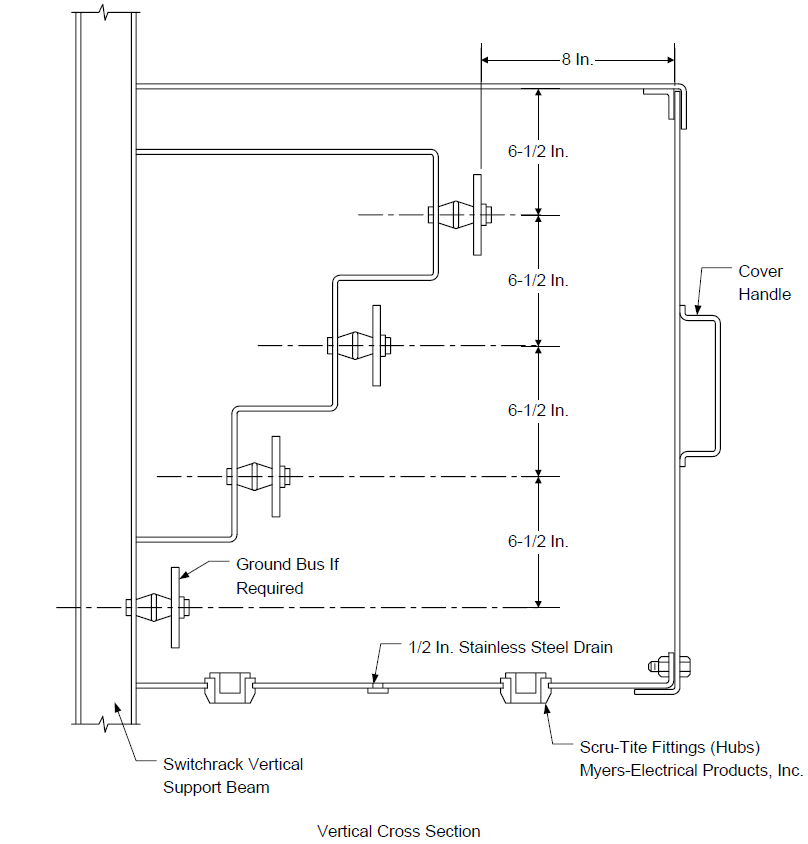
- See Figure 4 and Figure 5 for typical bus enclosure layout and cover design.
- Bus enclosure space heaters with thermostat shall be provided when specified on the Data Sheet. Space heater voltage shall be 120/208 volts. Space heaters and separate thermostat enclosure shall be suitable for the area classification specified.
- When the switchrack is specified as a single bus compartment unit with split bus, the buses and enclosure design shall be as follows:
- The buses shall be split/open at the location indicated on the Data Sheet or attached drawings.
- There shall only be one bus run in a bus compartment enclosure.
- Each bus compartment shall be separated from one another via a removable aluminum panel barrier.
- The buses shall line up at the split location in a manner to allow the owner to remove the bus compartment divider panel and install a bus splice plate to connect the buses together.
- The open bus end common sides shall be tin plated, taped/insulated to prevent corrosion (corrosion protection method shall be easily removable) and be pre–drilled for a copper bus splice plate. A set of pre–drilled plated copper bus splice plates shall be provided as a ship loose item.
- Equipment Enclosures
- Operating handles shall be a maximum height of six feet – six inches as measured from the top of the rack mounting feet.
- Unless specified otherwise on the Data Sheet, 20 percent spare space shall be provided for future addition of circuit breakers, motor starters, etc.
- Combination Starters and Feeder Breakers
Combination starters, feeder breaker assemblies, lighting/power panels and lighting/power transformers to be supplied with the switchback assembly shall”
- Be mounted on the switchrack and arranged as indicated on the attached drawings.
- Be in compliance with EP 13–7–2 and EP13–7–2 DS.
- Welding Receptacles and 120 VAC Receptacles
- Receptacles shall be provided as part of the switchrack assembly in the quantities and types as specified on the Data Sheet.
- 120 VAC receptacles shall be protected with a 20 ampere GFCI circuit breaker.
- Miscellaneous Devices
- Photocells, lights, bus thermostats, bus heaters, control panels, and controls shall be Class I, Division 2, Group C & D rated (or as otherwise specified on the Data Sheet), UL listed and/or UL classified and supplied in quantities and types indicated on the Data Sheet and/or purchase documents.
- Switchrack lighting shall be provided as follows:
- Unless specified otherwise on the Data Sheet, each equipped side of a switchrack shall have two fixtures, see Figure 1 and Figure 2.
- Fixtures shall be Crouse–Hinds VMV series, or Appleton Mercmaster III 175 watt, metal halide, 120 VAC lamps with clear glass (lamps shall be supplied).
- Lighting fixtures shall be controlled as indicated on the Data Sheet.
- Unless specified otherwise, 120 VAC power for local lighting shall be by others.
- Power Bus
- Power buses shall be copper with tin plated joints at all splices, sized as specified on the Data Sheet. Figure 4 and Figure 5 detail typical, preferred, power bus layout.
- Minimum spacing between bare live parts (phase spacing) shall be three inches between buses of opposite phase and three inches between bare live parts and ground.
- Four–bolt double–lap bus joints shall be provided for all bus joints.
- All load connections for #8 AWG wire and larger shall be made to the power and ground buses by double–bolt, double–crimp lugs. Connections for wire smaller than #8 AWG shall be with single bolt, double crimp lugs or double hole, double crimp lugs.
- Bus drilling shall be provided for all future spaces indicated on the Data Sheet.
- Bus load tap layout shall be such as to permit working the bus while energized.
- Bus bracing shall be 42,000 ampere symmetrical, unless specified otherwise on the Data Sheet.
- Silicone bronze nuts, bolts and washers shall be used for power connections.
- Wiring Methods
- Bus and enclosure load side conduit unions and seals shall be provided. Seals are not to be poured. However, sealing cement and fiber filler shall be provided.
- All conduit shall be rigid galvanized steel conforming to ANSI C80.1 and UL6 or aluminum conduit conforming to ANSI C80.5 and UL6, as specified on the Data Sheet.
- Control and power wire shall be stranded copper wire with 600 volt XHHW, XHHW–2 or RHW (EPR) insulation, minimum #12 AWG wire size.
- The minimum wire size for starter power wiring shall be as shown in Table 1.
- Wiring shall be labeled with typed heat shrinkable wire markers.
- When a main circuit breaker or switch is not used, a wiring chamber shall be provided for the incoming circuit. The wiring chamber shall be of the same construction, materials and rating as the main bus encloser. In addition the following shall apply:
- Locate at one end of the switchrack.
- Shall be under the canopy to afford protection from the weather.
- Provide necessary copper buswork in the chamber to allow direct vertical termination of incoming power cables (bottom entry) to the Owner’s double hole lug.
- Be oversized to allow for training (layout) of power cables.
- Shall be designed to allow access for vertical pulling of power cables into the chamber for bottom entry main feeder cables.
- All internal control wiring shall utilize compression type lugs, and shall have insulated sleeves and be the spade tongue type.
- Seal fittings shall be Crouse–Hinds or Appleton and be of Feraloy/Grayloy breakout type material.
- All seal fittings shall have drains.
- Grounding
- Provide a copper equipment grounding bus at both ends of the switchrack for a copper grounding cable (1/4 inch x 2 inch x 8 inch minimum) connection 20 inches above the base (See Figure 1 and Figure 2).
- The enclosure grounding shall be accomplished by running a horizontal bare #2 AWG copper wire the length of the structure with separate ground circuit taps taken to each enclosure. All tap connections to the main grounding wire shall be by exothermic weld. Daisey chaining of ground wire between enclosure is not acceptable. The use of mechanical connectors for tap connections to the main ground wire is unacceptable. Switchracks with back–to–back enclosures shall have a separate main ground wire on each side of the switchrack.
- A full length copper ground bus bar shall be provided in the power bus compartment. The bus shall be wired to the switchrack frame ground pad via a 2 AWG copper wire as shown in Figure 1. Each load enclosure feeder drop shall have an NEC sized ground wire run from the ground bus with the phase wires into the load enclosure and terminated to the enclosure with provisions for additional ground terminal block connections for use by the Owner.
- Nameplates
The following are additional nameplate requirements beyond the Manufacturers standard enclosure, starter nameplates.
- Each enclosure shall have a permanent identification nameplate. Nameplates shall be lamicoid tags, with bold black lettering on a white background. The minimum letter size shall be 3/8 inches high.
- Provide a stainless steel nameplate (with minimum 1/4 inch high lettering) affixed to a mounting leg that shall contain the following information:
- Switchrack Manufacturer’s (fabricator’s) name.
- Owner’s switchrack identification record number.
- Bus rating to include maximum ampere, bracing, voltage, wire, phase.
- Overall 480 volt unit rating as specified and provided (ampere withstand and/or ampere interrupting capacity).
- All nameplates shall be permanently fastened with either stainless steel screws or stainless steel nuts and bolts.
- Additional, unique, Owner nameplate information shall be provided to the Manufacturer after receipt of order. All nameplate information shall be reviewed and approved by the Owner prior to fabrication of nameplates.
TESTING
- Testing
- Testing shall be for all equipment supplied with the switchrack.
- In addition to the Manufacturer’s standard tests the following tests shall also be performed.
- All power bus, power wiring and control wiring shall have their insulation resistance verified. The test voltage shall be 1000 VDC.
- Perform a polarization index test on the switchrack bus and load taps, with load main disconnects open. The test voltage shall be 1000 VDC with the one minute to ten minute readings taken for the polarization index.
- With the main bus energized at 480V, three phase, the operation/functionality and phase connection of all equipment shall be verified.
- Witness Testing
When witness testing is specified, the Owner shall witness the complete testing of all items outlined in paragraph 6.1 and the contract documents.
DRAWING AND DATA REQUIREMENTS
- Information to be Supplied with Quotation
- Specific listing of any exceptions to those requirements specified.
- Equipment or features included but not necessarily specified.
- Information shall be provided for all equipment supplied with/on the switchrack.
- Drawings/sketches showing:
- Equipment layout/orientation with dimensions.
- Switchrack design/layout including mounting base, canopy and bus enclosure. Include proposed elevations, conduit and structural plans and installed weight.
- Details of main bus layout.
- Details of bus enclosure design including removable entrance panels.
- The proposal shall include a complete list of unit prices including the cost to add or delete any motor starter, circuit breaker enclosure etc.
- Complete lists and descriptive data of all equipment proposed shall be included.
- Quote must be for equipment as specified, including any requested alternatives. Manufacturer recommended alternatives are encouraged, but must be provided in addition to that specified with associated cost adds/deducts.
- Cost for witness testing, if specified.
- Information to be Submitted to the Owner for Approval After Receipt of Order
- Typical drawings are not acceptable, unless revised to show as–built equipment and identify the specific equipment ordered.
- Complete structural drawings showing:
- Equipment arrangement/layout with dimensions.
- Switchrack dimensional plan and elevation, front/back views, side views and other elevation views, if pertinent.
- Exact conduit entrance locations and dimensions for all bottom (top if required) entrance.
- Complete details on incoming power cable terminator positions and configuration.
- Detail drawing of mounting base along with all weights and moments required for Owner’s foundation and anchor design.
- Owners wiring terminal block locations.
- Identify all items that will require field assembly and provide details for field assembly, i.e. canopy assembly.
- Elementary diagrams (required when enclosures are provided with the switchrack per EP 13–7– 2 DS):
- Elementary diagrams (schematic) shall be furnished for each starter control scheme and drawn to ANSI standards.
- Each elementary diagram shall show all control devices and device contacts, each of which shall be labeled with its proper ANSI device function number.
- Detailed connection (wiring) diagrams showing (required when enclosures are provided with the switchrack per EP 13–7–2 DS):
- All wiring within each unit.
- Identification of all terminal blocks.
- All interconnecting wiring between units.
- Clear identification, by some distinguishing method of all wiring that is to be installed by the Owner.
- Detailed listing of all nameplates.
- Certified Information to be Supplied
- All information requested in paragraphs 7.1 and 7.2 “as built”.
- All test reports on all information as detailed in paragraph 6.0, the Data Sheets and requirements of the purchase documents.
- Installation, operating and maintenance instructions: Installation, operating and maintenance instructions shall cover all the equipment furnished including all protective devices (MCP, fuses, overloads etc.), auxiliary relays, etc.
- Spare parts listing.
- When specified on the Data Sheet, certified information shall be provided by electronic means as outlined in Table 2.
SPARE PARTS
A complete spare parts recommendation, with pricing, based on the total purchase order is required as specified on the Data Sheet. Spare parts recommendations shall include:
- A complete spare parts list, including parts location diagrams or drawings.
- Lists of priced spare parts as recommended by the Manufacturer to be on hand during plant start–up and the first year’s operation.
SHIPPING
- ‘Preparation for Shipment’ shall be in accordance with the Manufacturer’s standard, unless otherwise noted on the ‘Request for Quotation’ and/or Purchase Order. The Manufacturer shall be solely responsible for the adequacy of the ‘Preparation for Shipment’ provisions employed in respect of materials and application, to provide materials to their destination in ex–works condition when handled by commercial carrier systems.
- Each switchrack shall be equipped with recording impact meters.
- Parts and accessories, such as the canopy and lighting, which may be shipped separately, shall be prepared by the Manufacturer in a manner to prevent physical damage when handled by commercial carrier systems.
10.0 TABLES
TABLE 1
MINIMUM WIRE SIZES FOR POWER CIRCUITS
| Starter Size | Wiring |
|---|---|
| Size 1 Size 2 Size 3 Size 4 Size 5 |
#12 AWG #6 AWG #2 AWG #2/0 AWG #350 AWG |
TABLE 2
CERTIFIED INFORMATION REQUIRED IN ELECTRONIC FORMAT (1)
| Item | Description | Format (1) | As–Built |
|---|---|---|---|
| 1 | Complete certified structural drawings including but not limited to those items in paragraph 7.2.2. | See EP 2-5-2 | Yes |
| 2 | Certified elementary diagrams for all equipment provided per paragraph 7.2.3. | See EP 2-5-2 | Yes |
| 3 | Certified detailed connection (wiring) diagrams per paragraph 7.2.4. | See EP 2-5-2 | Yes |
| 4 | Certified listing of all nameplates provided including location identification. |
See EP 2-5-2 | Yes |
| 5 | Certified copies of all test reports to include requirements of Section 6.0 and those tests included in the purchase documents. | See EP 2-5-2 | Yes |
| 6 | Complete certified installation, operating and maintenance manuals for all equipment/items provided, paragraph 7.3.3. |
See EP 2-5-2 | Yes |
(1) NOTE: Information is for all equipment supplied with the switchrack.
11.0 FIGURES
FIGURE 1
TYPICAL ELEVATION, FRONT VIEW
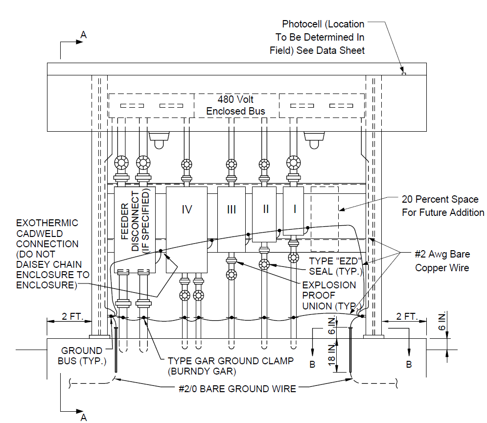
FIGURE 2
TYPICAL ELEVATION, END VIEW
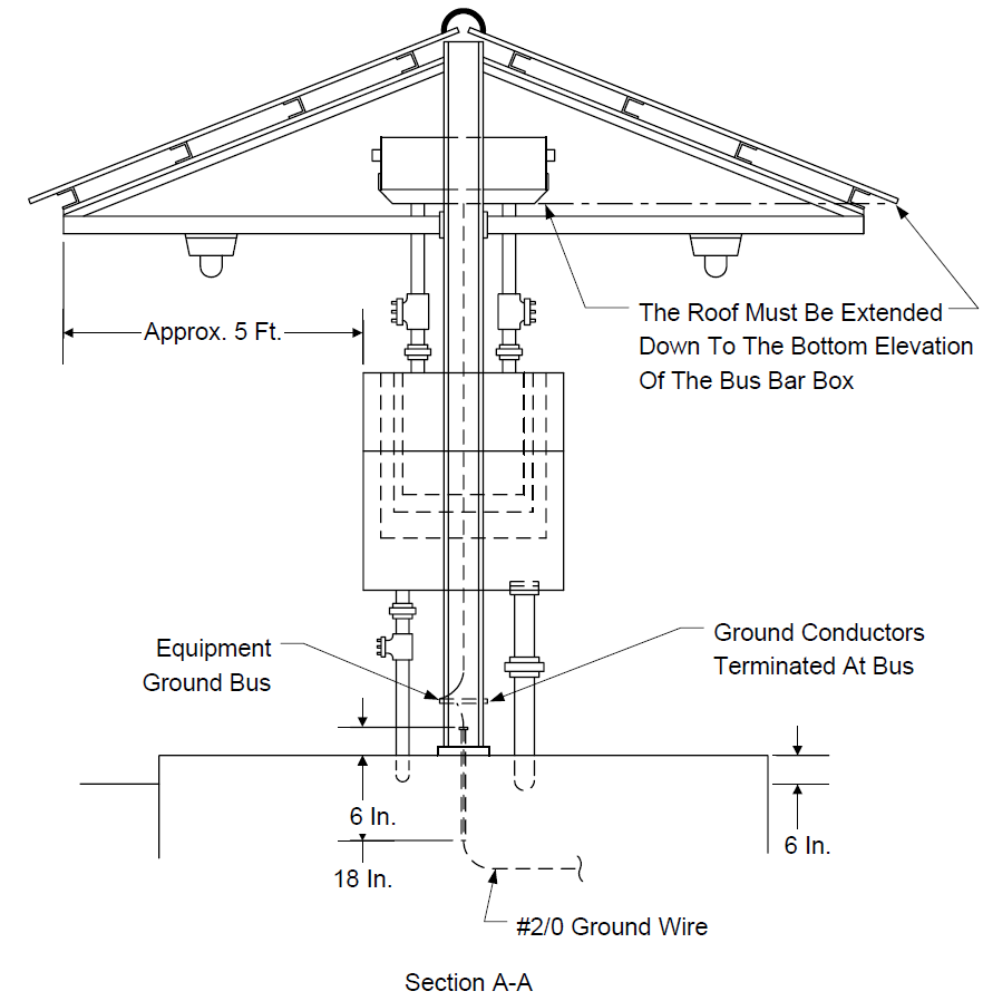
FIGURE 3 TYPICAL MOUNTING PLATE
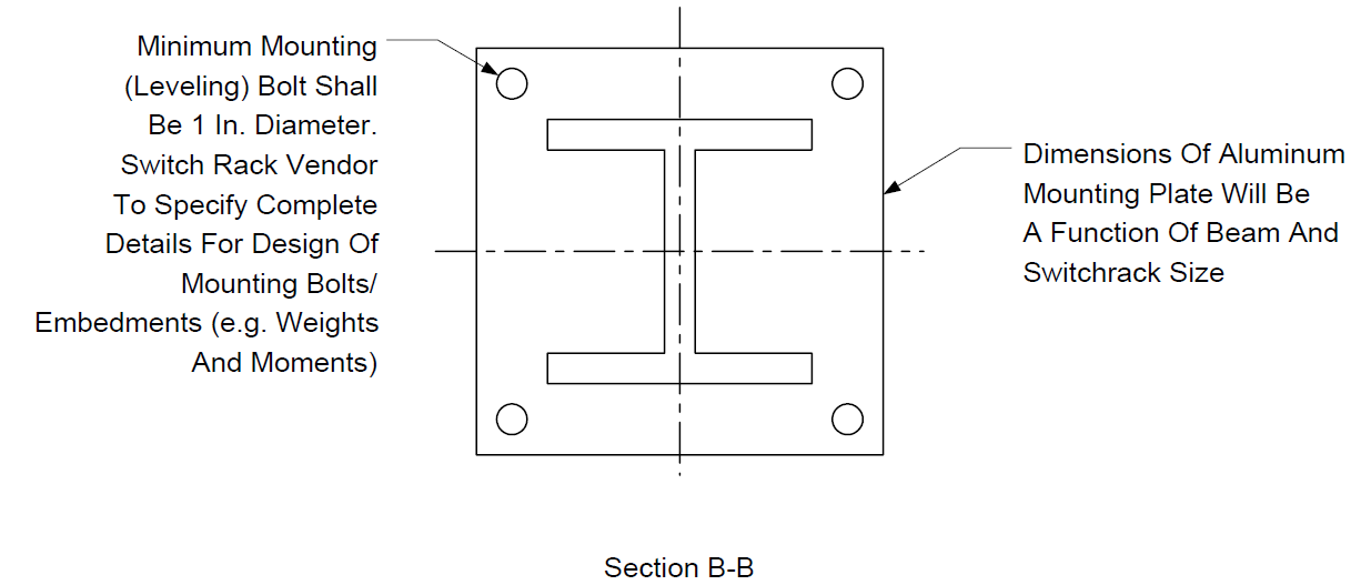
FIGURE 4
TYPICAL POWER BUS SECTION HORIZONTAL CONFIGURATION
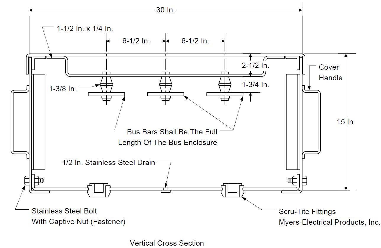
FIGURE 5
TYPICAL POWER BUS SECTION VERTICAL CONFIGURATION
© 2026 Inflection Point Engineering, LLC. All rights reserved. The content of this page — including calculation methods, reference data, written analysis, interactive tools, and source code — is the intellectual property of Inflection Point Engineering, LLC and is protected under applicable copyright, trademark, and trade secret laws. Unauthorized reproduction, redistribution, modification, or derivative use in whole or in part is prohibited without prior written consent.
Disclaimer. This material is provided for informational and educational purposes only and does not constitute professional engineering advice. Calculations, reference data, and methodologies are based on published standards and accepted engineering practice but are not a substitute for engineering judgment, site-specific analysis, or review by a licensed Professional Engineer. Inflection Point Engineering, LLC makes no warranties, express or implied, regarding the accuracy, completeness, or fitness for a particular purpose of any content presented here, and shall not be liable for any direct, indirect, incidental, or consequential damages arising from its use. Users assume all risk associated with applying this content to real-world design, operations, or decisions.
© 2026 Inflection Point Engineering, LLC. All rights reserved.