 Section 13 — Electrical
Synchronous Motors
IPE Engineering Practice IPE-EP-13-3-3
Document number: IPE-EP-13-3-3 · Section: 13 — Electrical
1.0
1.1
1.2
1.3
1.4
1.5
2.0
SCOPE
This Practice describes synchronous motors. Included as a part of this Practice are Data Sheets listing geographic and environmental information as well as the specific equipment requirements.
Only a service–proven design shall be offered. If a design is offered that has not been proven in service for at least two years, the proposal shall indicate which parts of the motor are affected (e.g., bearings, insulation, etc.) and the extent of experience with these parts.
This Practice is appropriate for attachment to an inquiry or purchase document when accompanied by the referenced IPE Engineering Practices and completed Data Sheets.
Any deviation from this Practice must be approved by the procedure described in EP 1–1–3. A revision bar indicates all changes made to this Revision.
REFERENCES
All applicable sections of the latest standards and codes listed below are a part of this Practice for construction and testing unless amended herein. It shall be the Manufacturer’s responsibility to be or become knowledgeable of the requirements of the standards and codes. Any changes or alterations to the equipment to make it meet the requirements shall be at the expense of the Manufacturer.
STANDARDS AND PUBLICATIONS
| IPE Engineering Practices |
|---|
| EP 1–1–3 Deviations to IPE Engineering Practices EP 6–9–1 Special Purpose Lube/Seal Oil Systems EP 13–3–3 DS Synchronous Motors Data Sheet |
| AFBMA Standards |
| Std 7 Shaft and Housing Fits for Metric Radial Ball and Roller Bearings Std 8.2 Mounting Accessories, Inch Design - Locknuts, Washers, and Adapters Std 9 Load Ratings and Fatigue Life for Ball Bearings Std 11 Load Ratings and Fatigue Life for Roller Bearings Std 20 Metric Ball and Roller Bearings (Except Tapered Roller Bearings) Conforming Basic Boundary Plans: Boundary Dimensions, Tolerances and Identification Code |
| AGMA Standard |
| 9002 Bores and Keyways for Flexible Couplings (Inch Series) |
STANDARDS AND PUBLICATIONS (Cont.)
| AISI Standards |
|---|
| C50.10 General Requirements for Synchronous Machines C57.13 Instrument Transformers C80.1 Rigid Steel Conduit, Zinc Coated |
| ANSI/IEEE |
| 43 Recommended Practice for Testing Insulation Resistance of Rotating Machinery 112 Test Procedures for Polyphase Induction Motors and Generators 115 Test Procedures for Synchronous Machines 303 Recommended Practice for Auxiliary Devices for Motors in Class I–Groups A, B, C, and D, Division 2 Locations |
| API Standards |
| Std 546 Form–Wound Synchronous Motors 500 Horsepower and Larger (only as referenced) Std 614 Lubrication, Shaft–Sealing, and Control–Oil Systems for Special–Purpose Applications Std 670 Vibration, Axial–Position, and Bearing–Temperature Monitoring Systems Std 671 Special–Purpose Couplings for Refinery Service Std 678 Accelerometer–Based Vibration Monitoring System |
| ASME Codes |
| Sec V Nondestructive Examination Sec VIII Pressure Vessels, Div Sec IX Welding and Brazing Qualifications |
| ASME/ANSI Standard |
| B16.5 Pipe Flanges and Flanged Fittings |
| ASTM Standard |
| A345 Flat–Rolled Electrical Steels for Magnetic Applications. |
| IEEE Standards |
| 85 Test Procedure for Airborne Sound Measurements on Rotatina Electric Machinery 429 Standard Test Procedure for the Evaluation of Sealed Insulation Systems for AC Electrical Machinery 522 Guide for Testing Turn–to–Turn Insulation Form–Wound Stator Coils for AC Rotating Electric Machines |
STANDARDS AND PUBLICATIONS (Cont.)
| NEMA Standards | NEMA Standards |
|---|---|
| 250 MGI |
Enclosures for Electrical Equipment (1000 Volts Maximum) Motors and Generators |
| NFPA Standards | NFPA Standards |
| 70 497M |
National Electrical Code Classification of Gases. Vapors and Dusts for Electrical Equipment in (Classified) Locations |
| SSPC Standards | SSPC Standards |
| SP6 | Commercial Blast Cleaning |
| UL Standards | UL Standards |
| 1 | Flexible Metalconduit |
DEFINITIONS
- Contractor – Company or business that agrees to furnish materials or perform specified services at a specified price and/or rate to the Owner.
- Inspector – A Inflection Point Engineering, LLC appointed engineer or inspector.
- Manufacturer – The recipient of a direct or indirect purchase order for materials and/or equipment. In this context, a direct order is one issued to a Manufacturer by a Contractor or the Owner. An indirect order is one issued to a Manufacturer by a vendor (recipient of a direct order) for materials, fabricated components, or subassemblies.
- Owner – Inflection Point Engineering, LLC.
- Owner’s Engineer – A Inflection Point Engineering, LLC appointed engineer.
- Purchaser – The party placing a direct purchase order. The Purchaser is the Owner’s designated representative.
SERVICE CONDITIONS
- Motors shall be designed for continuous outdoor operation without protective shelter, and they shall be adequate for withstanding driven rain and snow. Unless otherwise noted, on the Data Sheet (EP 13–3–3 DS), the motors shall be for use in a 104ºF maximum ambient, –15ºF minimum ambient and at an altitude of 3,300 feet or lower.
- When ammonia or H2S fumes are listed as an environmental condition on the Data Sheet, there shall be no copper parts exposed to atmosphere. All exposed parts shall be corrosion resistant.
- All electrical components shall be suitable for the area classification specified on the Data Sheet.
DESIGN, CONSTRUCTION AND MATERIALS
- General Performance Requirements
- Voltage and Frequency Variations
- Starting: The motor shall start and accelerate to running speed the connected load within the voltage and frequency variation specified below without injurious heating to any portion of the motor. For loads with other characteristics, the starting voltage and frequency limits may be different and will be specified on the Data Sheet.
- Running Conditions
- The motor shall start and operate successfully under running conditions at rated load with a variation in the voltage or the frequency up to the following:
- Plus or minus 10 percent of the rated voltage (with rated frequency).
- Plus or minus 5 percent of the rated frequency (with rated voltage).
- A combined variation in voltage and frequency of 10 percent (sum of the absolute values) of the rated values, provided the frequency variation does not exceed plus or minus 5 percent of the rated values.
- Performance within these voltage and frequency variations will not necessarily be in accordance with the standards established for operation at rated voltage and frequency.
- Load Requirements: The motor and driven equipment Manufacturers shall jointly assume responsibility for the proper starting, including determination of load speed torque requirements.
- Starting Capabilities
- The motor shall be designed for across–the–line starting.
- Motors shall have the starting capabilities shown in Table 1.
- The equipment shall conform to the maximum allowable sound pressure level as specified on the Data Sheet. The measuring and reporting of sound–level data shall be in accordance with IEEE 85.
- Performance
- The minimum safe stall time (locked rotor) time shall be the greater of 150% of, or 5 seconds more than, the time to accelerate the actual driven load. If these conditions cannot be met, the Manufacturer shall notify the Owner so that a workable solution can be jointly developed. The method of safe stall time calculation and the limits shall be described in the proposal.
- The maximum locked–rotor current shall not exceed 500 percent of the full–load current, unless specified otherwise on the Data Sheet.
- The minimum locked–rotor, pull–in and pull–out torques shall not be less than the values listed in MG–l Section 21.
- Current pulsations under the actual operating conditions shall be within the limits stated in API 618 or NEMA MG 1–21.84, as specified on the Data Sheet.
- Reacceleration of Loads
When specified on the Data Sheet, the motor and control/relaying shall be designed to provide prompt reacceleration of the motor following a power failure. The Data Sheet entries provide details on:
- Maximum interruption time
- The voltage available to accelerate the motor and load
- Information on load condition i.e. is a loaded start required, can reciprocating compressor be started loaded or is compressor unloading possible. It is critical that the driven equipment condition be properly quantified to insure that equipment in service can be re– accelerated.
- Load speed–torque curves that identify typical and worst case re–acceleration loadings
- Unless specified otherwise, the load torque characteristics shall be in accordance with NEMA MG–1 Section 21. In all cases the motor Manufacturer shall be responsible to coordinate the motor design with the driven equipment to insure motor design capability to start and run the load. Analysis shall include:
- The speed torque characteristics of the load are evaluated under the most stringent starting conditions.
- The wk2 load inertia shall include all loads that will be connected to the motor shaft, such as couplings, gearbox,etc.
- Electrical Design Features
- Stator Windings:
- Self–balancing differential protection shall be provided. Both ends of each stator phase winding shall be brought out to the power lead terminal box that houses the differential protection current transformers. The current transformer ratio shall be 50:5. All leads shall be insulated for full voltage.
- Winding Bracing: The winding end turns shall be adequately braced and supported to eliminate coil vibration or shift under high current conditions as well as repeated full voltage starts.
- Insulation System (For all components including armature, field and exciter )
- All motors shall have epoxy base, vacuum impregnated, non–hygroscopic insulation system, including leads and connections to the windings. When bus bars are used, they shall be insulated. The thermal rating of the coil connections shall be equal to that of the coil.
- All stator and armature coils shall be secured tightly in their slots. The winding end turns shall be adequately braced and supported to withstand the starting capabilities as indicated in paragraph 5.1.3.2.
- Motors shall have Class F insulation with a Class B temperature rise by resistance at 1.0 loading factor and rated power factor.
- Exciter armature and exciter field insulation shall be Class F, using highly moisture and chemical resistant cured material. The conductor strands shall be individually insulated by an enamel coating and/or glass weave that is saturated with varnish to provide turn–to–turn insulation. Exciter armature and field allowable temperature rise above ambient (40ºC) shall not exceed that listed in NEMA MG 1–21.40 for Class B insulation.
- The main field insulation system shall be highly moisture and chemical resistant. All parts used to form the field system shall be non-hygroscopic. The insulation integrity shall be maintained while withstanding the operating centrifugal forces, and thermal stress at the specified insulation class temperature rise without damage.
- All insulation systems shall be impervious to all commonly encountered contaminants in petrochemical environments. In addition, it shall withstand any special operating conditions specified on the Data Sheet.
- All motors shall have a sealed insulation system (NEMA MG 1–1.27.2). The insulation method shall be premium grade, mica flake (mica flake paper wrapper) epoxy resin, vacuum impregnated and cured. A minimum of 2 complete VPI cycles shall be applied.
- All stators shall have sealed insulation systems that are capable of withstanding an immersion test in accordance with NEMA MG 1–20.49.
- All stator insulation systems shall be service proven and shall have had thermal evaluation in accordance with IEEE 429.
- Stator leads with rubber based insulation such as EPR shall be jacketed, taped or sleeved with an oil resistant material such as PVC.
- Leads from the exciter rectifier diodes to the field winding shall have Class “H” insulation.
- All medium voltage bus work used in the motor or motor terminal box shall be copper with tin plated joints, fully insulated with non–hygroscopic materials and supported with either porcelain or cycloaliphatic epoxy insulators.
- All metal conduits shall be rigid galvanized steel conduits conforming to ANSI C80.l and UL 6. Flexible metal conduit shall be liquid tight suitable for the area classification, in compliance with NFPA 70 for grounding and listed per UL 1.
- Mechanical Design Features
- Enclosures:
- Enclosure parts may be made of cast iron, cast steel, sheet steel, or steel plate. Owner approved reinforced plastic may be used for parts such as covers or non–supportive enclosure sections; these parts shall have rigidity (mechanically) equivalent to 1/8 inch sheet steel.
- Air deflectors shall be made of corrosion–resistant material or have corrosion–resistant plating or treatment suitable for the environmental conditions.
- All hardware, bolts, studs and other fastening devices of the enclosure shall be made of Series 300 stainless steel.
- The enclosure shall be designed to facilitate cleaning and painting of the motor interior.
- When abrasive dust conditions have been specified on the Data Sheets, electrical insulation shall be protected from the abrasive action of airborne particles.
- The impact or potential risks due to possible circulating currents in the enclosure should be considered for motors using multi–section enclosures installed in classified locations. Overheating or sparking due to possible circulating currents shall be avoided, where necessary, by bonding together the conducting components in a secure electrical and mechanical manner, or by the provision of adequate bonding straps between the motor housing components.
- All fabricated welded structural steel shall be post–weld stress relieved. This does not apply to sheet metal components.
- Stator
- Stator Housing (Frame):
- The frame shall be of cast or nodular iron, cast steel or welded steel plate construction with removable end bells or end plates to permit removal of the rotor and facilitate replacement of stator coils. The frame of the completely assembled machine on its permanent foundation, with the rotor installed and rotating on its oil film, shall be free from structural resonance within ± 5 percent of electric line frequency and twice line frequency and the following frequency ranges: N where N = (nNop ± 0.20 Nop) and Nop equals the operating speed and n = 1, 2, and 3.
- The stress values used in the design of the frame shall not exceed the maximum allowable stress criteria specified in Section VIII, Division 1, of the ASME Boiler and Pressure Vessel Code (commonly called the ASME Code) for materials used. Conditions evaluated should include short circuits, out–of–phase synchronism, thrust, handling, and specified seismic loading.
- The motor frame, including transition base (if supplied) and the bearing supports, shall be designed to have sufficient strength and rigidity to limit changes of alignment caused by the worst combination of torque reaction, conduit/piping stress, magnetic imbalance, and thermal distortion to 0.002 inches at the coupling flange (This is not to be confused with the normal repeatable thermal growth between ambient and operating temperatures).
- Frames on horizontal motors shall be rigid enough to permit the machine to be moved by using the lateral, axial, and vertical jack screws.
- Horizontal motors shall be equipped with vertical jackscrews appropriately located to facilitate coupling alignment. If size and weight prohibit the use of jackscrews, other provisions shall be made for vertical jacking. When sole plates are provided (specified) they shall be supplied with lateral and axial jack screws.
- Frame mounting surfaces on horizontal motors shall be machined on a common plane parallel to the theoretical centerline of the motor. The mounting surfaces shall be machined within 0.005 inch of a plane through the lowest foot, and each foot shall be parallel within
0.002 inch per foot to that plane in the transverse or longitudinal direction.
7) The mounting surface of vertical motors shall be machined perpendicular to the motor
centerline, and this surface shall not deviate from that perpendicular plane by more than
0.002 inches per foot.
- Motor frame mounting surface tolerance for unlevelness shall be a maximum of 0.001 inches per foot.
- The machined finish of the mounting surface (sole plate and motor frame) shall not exceed 250 micro inches arithmetic average roughness (Ra). Hold–down or foundation bolt holes shall be drilled perpendicular to the mounting surface or surfaces and spot faced to a diameter 1.5 times that of the bolt diameter, when the surface is a cast or other un- machined uneven surface.
- Sole plate tolerance for unlevelness shall be a maximum of 0.002 inches per foot.
- Mounting plates shall be large enough to provide ample space for easy placement of a precision machinist’s level, Starrett 98 or equal. Sufficient space shall be provided on all equipment foot pads/mounting surfaces in both directions for leveling purposes.
- Lifting lugs, through holes, or eyebolts shall be provided for lifting major components and the assembled motor. Any special mechanisms for lifting major components and the assembled motor shall be identified by the Manufacturer and priced as a separate line item in the quotation.
- All fabricated welded structural steel shall be post–weld stress relieved.
- Stator Core
- Stator core shall be built–up from laminations of low loss high permeability type steel. These laminations are to be deburred and insulated to reduce eddy current losses.
- Stator lamination core plate shall be of at least C–5 quality per ASTM A 345. C–3 shall not be used, even along with C–5. The stator core shall be capable of withstanding winding burnout for rewind at 750ºF without damage or loosening.
- Rotor/Shaft System: Single–piece rotor construction is not acceptable.
- Shaft
- The shaft shall be one–piece, heat–treated, forged steel (AISI 4140 Grade) suitably ground. The rotating element materials and design shall be selected to withstand the starting duties specified in this practice with a fatigue life greater than 5000 full–voltage starts.
- When non–contacting radial vibration and/or axial–position probes are furnished, or when provisions for probes are required, the rotor shaft sensing areas to be observed by radial– vibration probes shall be concentric with the bearing journals. All shaft sensing areas ( both radial vibration and axial position) shall be free from stencil and scribe marks or any other surface discontinuity, such as an oil hole or a keyway, for a minimum of one probe–tip diameter on each side of the probe. These areas shall not be metalized, sleeved, or plated. The final surface finish shall not exceed 32 microinches Ra, preferably obtained by honing or burnishing. These areas shall be properly demagnetized or otherwise treated. For areas to be observed by radial vibration probes, the combined total electrical and mechanical runout shall not exceed 0.25 mils. If the runout is greater than 0.25 mils and less than 25 percent of the maximum allowed peak–to–peak unfiltered vibration amplitude (refer to Figure 2 ), then an additional burnishing operation shall be performed. If after a second burnishing operation the runout is less than or equal to 25 percent of the maximum allowed peak–to–peak unfiltered vibration, then that shall constitute an acceptable runout level. For areas to be observed by axial–position probes, the combined total electrical and mechanical runout shall not exceed 0.5 mil.Figure 2
- The shaft shall be ultrasonically inspected prior to assembly.
- Shaft end at coupling fits shall conform to the requirements of API 671.
- All keyway cuts shall have a radius to reduce stress concentrations. The bottom corners of all keyway radii shall be at least one–eight of the keyway depth.
- Poles
- On laminated poles, laminated pole shoes, or laminated cylindrical rotors, the laminations shall have no burrs in excess of 0.003 inch. Laminations shall be distributed when stacked to minimize uneven buildup and to evenly distribute magnetic properties in grain orientation. The method of assembly shall prevent shaft surface scoring, assure positive positioning, and minimize bowing. No shaft straightening technique shall be permitted during or after rotor fabrication. Shaft repair by plating or metal spray is not acceptable without the Owner’s approval.
- The method of attachment of the bars to the current–carrying end ring shall be selected to minimize localized heating and the non-uniform stresses that result. The bars shall be radially supported as necessary in the current–carrying end ring to prevent the braze or weld from being overstressed. The metal joining material shall not be subject to attack by hydrogen sulfide (that is, it shall be phosphorus–free material). Inert gas welding or induction brazing is preferred. Outward bending of rotor bar ends and shorting ring articulation shall be limited by design, material selection, or shrunk–on or fitted steel retainer rings.
- Rotors with solid pole heads shall have easily removable field coils. The bolts that retain the laminated or solid pole heads shall be secured by methods that allow easy bolt removal and that are approved by the Owner.
- Motors with fabricated–bar armortisseur windings shall be furnished with copper or copper alloy bars and end rings.
- Retaining rings without circumferential joints are required for motors intended to operate at synchronous speeds greater than or equal to 1000 revolutions per minute.
- Copper/copper alloy bars and end ring material and processes shall be selected to minimize hydrogen embrittlement.
- It is preferred that fans be separately mounted and not integrally cast with the end rings. Separable fans shall be permanently indexed angularly and axially and mounted by one of the following methods:
- Bolted to the rotor retaining ring or to the field winding support.
- Split hub on shaft.
- Shrink–fit or directly bolted on shaft.
- Spider mounted.
- Slip–fit fans secured only with set screws to the shaft are not acceptable. Removal and reassembly of the fans to the rotor shall not change the rotor balance enough to exceed the allowable residual unbalance limits.
- Balance
- Rotors shall be dynamically balanced in two or more planes. The use of solder or similar deposits for balance correction shall not be acceptable. Parent metal removed to achieve dynamic or static balance shall be drilled out in such a manner as to not affect the structural strength of the rotor. Chiseling or sawing shall not be permitted.
- Rotors with single keys for couplings shall be balanced with a half key in place. The half key used for balancing shall be dynamically equivalent to a half key which completely fills the keyway. A crowned half key is preferred.
- Rotor balance shall not be accomplished by adding balance weights on the fan blades. After final balance of the main rotor, the fans, exciter, and other removable rotor components shall be installed and component (step) balanced.
- Unless specified otherwise, the Owner’s balanced coupling shall be mounted by the motor manufacturer and the rotor balance re–checked. Any increase in unbalance shall be reported to the Owner. Any changes to the rotor or coupling balance shall be mutually agreed to by the Owner and Manufacturer.
- For the final balancing of the rotor in the balancing device, the maximum allowable residual unbalance in the correction plane shall be determined from the following equation:
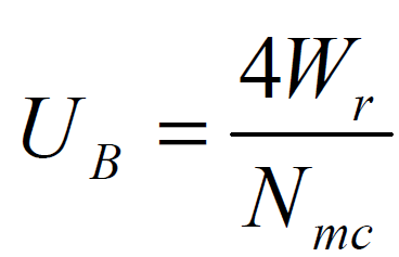
where:
UB = Residual unbalance, in ounce–inches
Wr = Journal static loading, in pounds
Nmc = Maximum continuous speed, in revolutions per minute
- After completion of final balancing of the assembled rotor, a determination of residual unbalance shall be performed as outlined in the appendix of API 546. A report of residual unbalance shall be provided with the certified test data.
- Vibration
- The radial vibration level measured on a bearing housing with the machine operating at rated voltage and frequency at any load shall not exceed the limits presented in Figure 1.
- The maximum unfiltered and filtered shaft displacement relative to the bearing housing, with the machine operating at rated voltage and frequency at any load, shall not exceed the limits given in Figure 2.
- For machines that do not have non–contact vibration probes or provisions for probes, the shaft vibration displacement limits are the same as given above, 5.3.5.2. A shaft–rider is not an acceptable substitute for non–contact vibration probes when non–contact vibration probes or provisions for vibration probes are specified. Contract probes shall be used when provided or shop probes shall be used, when provisions for probes is specified.
- Vibration Probes: When specified on the Data Sheet, non–contacting vibration probes and/or provisions for shall be supplied, and mounted as follows:
- Horizontal Motors: Two radially oriented probes shall be provided (or provisions for) for each bearing.
- Vertical Motors: Two axial position probes shall be provided (or provisions for) for the hydrodynamic thrust bearings.
- Vibration and position equipment shall be furnished and installed in accordance with API Standard 670 except as described by the following. Non–contacting vibration probes shall be mounted through the bearing centerline, monitoring the shaft journal, where possible. If not possible due to oil ring interference or other bearing construction features, the probes shall be mounted inboard of the bearing (toward the rotor). Where either of the above is not possible due to construction characteristics, the vendor shall state this in the proposal and the probes may be mounted outboard of the bearing, but not near a nodal point.
- Each probe lead and extension shall be plainly marked with stainless steel tags to indicate the probe location and service.
- All rigid conduit used for extension cables shall be rigid galvanized steel (RGS).
- Flexible conduit use at probes to RGS transitions shall be listed flexible conduit. The length of flexible conduit shall be minimized to facilitate maintenance and device removal.
- A gasketed, stainless steel junction box shall be provided outside the machine for all cable connections and vibration equipment devices to facilitate servicing while the machine is running.
- If required, the proximiter housing enclosure shall be a gasketed, fabricated stainless steel box (other materials may be supplied with approval of the Owner).
- Enclosures and Corresponding NEMA Specifications
- Requirements for Weather–Protected Type II Motors
- Weather–protected Type II motors shall conform to NEMA MG 1.25.8.2.
- All ventilation openings and passages shall be contained within the motor enclosure. Motors shall be suitable for mounting on conventional foundations or bedplates.
- Enclosures shall be designed to facilitate rust removal and spray painting of the motor interior without breaking any welded joints.
- Drain holes shall be provided at all locations in the enclosure where water might collect.
- All bolts, studs, other fastening devices, and balance washers of the motor shall be made of corrosion resistant 300 Series stainless steel.
- All weather protected Type II motors shall be provided with stainless steel filters per paragraph 5.4.5.
- Requirements for Totally Enclosed Water Air Cooled Motors
- Totally enclosed water air cooled motors shall conform to NEMA MG 1.26.8.
- Cooling water temperature, pressure, fouling factor shall be specified on the Data Sheet.
- The heat exchanger shall be of double tube construction and mounted on top of the motor.
- The interior of the motor shall be baffled or otherwise constructed to prevent water from cooler tube leaks directly striking the motor windings. The design shall assure that water from cooler leaks will collect and drain from the motor before reaching the level of the windings.
- The annular space between tube walls of double tube coolers shall be drained to an inspection point outside the cooler housing. An enclosed float switch, with alarm contact for the Owner’s use, and collecting pan shall be provided and mounted externally on the motor housing. Switch enclosure shall be suitable for the specified area classification of the motor location.
- Motors shall have provision to accept a purge gas from an external source when specified on the Data Sheet. Shaft seals shall be designed to minimize leakage. The maximum purge pressure & air leakage rates shall be provided to the Purchaser.
- Paragraphs 3, 4, 5, and 6 of Paragraph 5.3.7.1 are also applicable.
- Other Enclosures: Drip–proof and other Data Sheet specified enclosures shall conform to applicable NEMA standards and requirements noted on the Data Sheet.
- Bearings and Bearing Housing
- Unless otherwise specified, hydrodynamic radial bearings (e.g. sleeve or tilting pad) shall be provided on all horizontal motors.
- Antifriction bearings shall be used for vertical motors and when specified for horizontal motors, providing that the following conditions are met:
- Where the dN factor is less than 300,000 [The dN factor is the product of bearing size (bore) in millimeters and the rated speed in revolutions per minute].
- For horizontal motors a standard anti-friction bearing shall meet an L10 rated life of either 100,000 hours with continuous operation at rated conditions or 50,000 hours at maximum axial and radial loads and rated speed (The rated L10 life is the number of hours at rated bearing load and speed that 90 percent of a group of identical bearings will complete or exceed before the first evidence of failure). See AFBMA Standards 9 and/or 11.
- Thrust bearings for vertical motors shall be rated for AFBMA L10 life of 5000 hours (minimum continuous service at 200% of the maximum up and down thrust the load may develop during starting or while operating at any capacity on the rated performance curve).
- Hydrodynamic radial bearings shall be split (not applicable to double–shell, totally enclosed, fan–cooled enclosures) for ease of assembly and shall be of the precision–bored–sleeve or pad type, with cast iron, steel, or bronze backed babbitted replaceable liners, pads, or shells. Bearings shall be equipped with anti-rotation devices and shall be positively secured in the axial direction. The bearing design shall suppress hydrodynamic instabilities and provide sufficient damping to limit rotor vibration to maximum specified amplitudes while operating loaded or unloaded at specified operating speeds, including operation at any critical frequency if that critical frequency is a normal operating speed. The liners, pads, shells, rings and seals shall be horizontally split housings and shall be replaceable. The bearing housing design shall not require removal of the lower half of end bells or plates, duct work, or the coupling hub to permit replacement of bearing liner, pads, shells, rings and seals.
- Ball–type thrust bearings shall be of the duplex–matched, single–row, 40–degree, angular contact type (Series 7000) installed back to back.
- Thrust bearings for vertical motors shall be on top and preloaded and a single bearing. Tandem bearing assemblies shall not be used, unless approved by the Owner.
- Bearing housings for hydrodynamic bearings designed for pressure lubrication shall be arranged to minimize foaming. The drain system shall be adequate to maintain the oil and foam level below shaft end seals and allow sufficient oil level for oil–flinger–disk or oil ring(s) operation. Oil temperature rise for all hydrodynamic bearings shall not exceed 50ºF under the most adverse specified operating conditions when inlet oil temperature is 120ºF. Where inlet oil temperatures exceed 120ºF, special consideration shall be given to bearing design, oil flows, and allowable temperature rise.
- Bearing housings for horizontal motors shall be equipped with split, labyrinth–type end seals and deflectors where the shaft passes through the housing; lip–type seals shall not be used. Deflectors shall be made of non–sparkling materials. The labyrinth deflector design shall effectively retain oil in the housing and prevent entry of foreign material into the housing. No oil shall leak past the seal into the interior of the machine.
- Housings for ring–oil–lubricated bearings shall be provided with plugged ports positioned to allow visual inspection of the oil rings while the equipment is running.
- Anti–friction bearings shall be retained on the shaft and fitted into housings in accordance with the specifications of the AFBMA Standard 7. However, locking of ball thrust bearings to the shaft shall be restricted to a nut with a tongue–type lockwasher, for example, Series W of AFBMA STD 8.2.
- Anti–friction bearings, except for the angular–contact type, shall have a loose internal clearance fit equivalent to AFBMA Symbol 3 (AFBMA Std.20); single–row or double–row bearings shall be of the Conrad type. Filling–slot (maximum load) anti–friction bearings shall not be used. Bearing housing mounting surfaces shall be flat and in the same plane, machined perpendicular to or parallel with the bearing bore, as required. Bearing housings on motors shall be positively located by cylindrical precision dowels or rabbet fits. Bearing housings and support structures shall be designed so that, upon assembly, none of the air–gap measurements taken in at least three positions each spaced 90º apart at both ends of the motor deviates from the limit given in paragraph 5.3.8.11 below for the main or exciter air gap, as defined by the following equation:
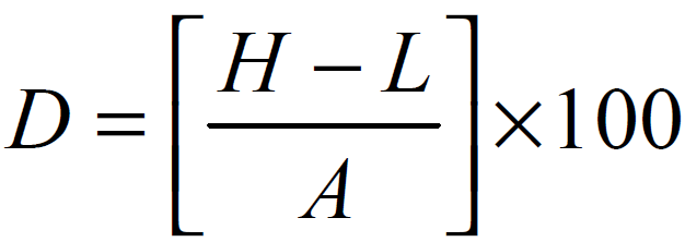
Where:
D = percent deviation.
H = the highest of the three readings at one end. L = the lowest of the three readings at that end. A = the average of the three readings at that end.
- The air gap between the exterior of the rotor and the interior of the stator must be measured at both ends of the motor. Measurements shall be taken at the same positions defined above. The percentage deviation shall not exceed 10 percent for the main air gap and 15 percent for the exciter air gap. This data is to be recorded and made part of the final report. NOTE: Stator surfaces at the measuring positions shall be free from resin buildup to allow for accurate measurement.
- All bearings shall be electrically insulated. A shorting device shall be provided on the drive end bearing housing.
- Hydrodynamic thrust bearings for vertical motors shall be of the babbitted multiple–segment type. Tilting–pad–type bearings shall incorporate a self–leveling feature assuring that each segment carries an equal share of the thrust load. The thrust collar shall be replaceable. Fretting and axial movement shall be prevented either by positively locking the collar to the shaft or by other methods. The thrust faces of the collar shall have a surface finish not exceeding 16 microinches root mean square, and the total indicated axial runout of either thrust face shall not exceed 0.0005 inch. Split thrust collars are not acceptable.
- Hydrodynamic thrust bearings for vertical motors shall be sized for continuous operation at no more than 50 percent of the bearing manufacturers rating. In addition to thrust from the rotor weight, the maximum axial force from the driven equipment transmitted through the coupling shall be considered a part of the duty of any thrust bearing.
- At ambient temperature conditions, the fit between the outside of the bearing shell and the bearing housing shall be line–to–line (zero clearance) and shall preferably be a light interference fit.
- Lubrication Systems
- Bearing housings for oil–lubricated non–pressure–fed bearings on horizontal motors shall have reservoirs of sufficient depth to serve as settling chambers. The housings shall each be provided with 1/2 inch minimum national pipe thread (NPT) tapped–and–plugged, fill and drain openings. The sump oil temperature shall not exceed 180ºF based on the specified operating conditions and an ambient temperature 104ºF. Non–pressurized systems shall be equipped with 8–ounce minimum size constant–level sight–feed oilers with a positive level positioner (not a set screw), transparent containers (not subject to sunlight or heat–induced opacity or deterioration), and protective wire cages and supplemental support in addition to the piping. A permanent indication of proper oil level shall be accurately located and clearly marked on the outside of the bearing housing with permanent metal tags, marks inscribed in the castings, or other durable means. In case of accidental breakage of the oil level indicator, a drop in oil level shall not result in loss of bearing lubrication, i.e., oil level reduction below level required for oil ring operation. The oil system shall have sufficient surge capacity to absorb, without overflowing, all oil returned from the bearings when the motor is stopped. The bearing housing shall be fitted with fill and drain openings and the necessary flingers, equalizers, vents, or other devices to prevent loss of lubricant.
- Oil for motors requiring forced–feed lubrication shall be supplied from the driven equipment lubrication system, if a suitable system is available. In this case:
- The motor Manufacturer shall specify required motor oil flow, pressure and quality requirements, and the heat rejection rate.
- Supply oil rings for start–up and emergency operation and designed to allow for orderly shutdown in the event of forced feed system failure.
- All oil piping will be furnished by the driven equipment vendor. Piping shall meet the same specifications as the driven equipment piping. Sight flow indicators for each bearing and a flow or pressure switch shall also be provided.
- When a forced–feed lubrication system is supplied with the motor, the system shall conform to EP 6–9–1 and include:
- A shaft–driven or separate motor–driven pump.
- An adequate lube oil cooling system.
- Oil rings for start–up (motors with shaft–driven pumps) and emergency operation.
- Duplex filters to permit change without shutdown.
- A pressure controller and a bypass relief valve if the oil pump is of the positive displacement type.
- A pressure gauge downstream of the filter, dial thermometer to indicate oil temperature, sight flow indicators for each bearing, and a flow or pressure switch.
- Oil level indicators for each bearing housing.
- An observation port for visual check of rotation of oil ring.
- The following conditions apply when oil mist lubrication is specified for anti–friction bearings:
- An oil mist inlet connection, 3/8–inch nominal pipe size, shall be provided in the top half of the bearing housing. The pure or purge mist fitting connections shall be located so that oil mist will flow through the anti–friction bearings.
- A vent connection, 1/2 inch nominal pipe size, shall be provided on the housing or end cover for each of the spaces between anti–friction bearings and the housing shaft closures.
- When pure or purge oil mist lubrication is specified, shielded or seal–type bearings shall not be used.
- When pure oil mist lubrication is specified, oil rings or slingers, a constant level oiler and a mark indicating oil level are not required.
- The motor Manufacturer shall furnish insulating fittings in the oil supply connections to prevent the oil supply lines from bypassing the bearing insulation.
- Sufficient cooling, including an allowance for fouling, shall be provided to maintain oil temperature below 170ºF for pressurized systems and below 180ºF for ring–oiled or splash systems based on specified operating conditions and an ambient temperature of 104ºF. Where water cooling is required, water jackets shall have only external connections between the upper and lower housing jackets and shall have neither gasketed nor threaded connection joints, which may cause water leakage into the oil reservoir. Cooling coils (including fittings), if used, shall be of Series 300 stainless steel and shall have no internal pressure joints or fittings. Coils shall have a minimum thickness of 0.042 inch and a minimum diameter of 1/2 inch.
- End Play and Coupling
- Horizontal sleeve–bearing motors shall have a total end play of at least 1/2 inch. Provide a factory–set magnetic center indicator device. The running center of the rotor shall not shift from either side of the geometric center by more than 3/32 inch.
- Flexible couplings used with horizontal sleeve–bearing motors will be of the limited–end float type with the end–float limited to 3/16 inch. The Manufacturer will be advised of the exact float of the coupling used.
- When the limited end float coupling is used, the motor shall have a permanent indicator to show the magnetic center and allowable limits of shaft movement after coupling installation and alignment. The indication method shall be durable and be adjacent to a shaft shoulder, and shall show the allowable excursion of the shaft.
- Cylindrical interference fit shall be in accordance with AGMA 9002.
- Taper fit motor couplings shall be in accordance with API 671.
- The Purchaser of the coupling shall supply an idling adapter, as required for the mechanical running test. Testing with the contract coupling is required. If it is not practical (with approval of the Owner), the mechanical running test shall be performed with a coupling and coupling hub idling adapters in place, resulting in moments equal to (± 10 percent) the moment of the contract coupling hub plus one–half that of the coupling spacer. When all testing is completed, the idling adapters shall be furnished to the Owner as part of the special tools.
- Dynamics
- When specified, the driven–equipment Manufacturer, the motor Manufacturer, or both shall perform a steady–state and transient torsional and stress analysis of the motor and driven equipment, including gears, motor driven pumps, and fan–or turbine– assisted units. The driven–equipment Manufacturer shall be responsible for the complete and satisfactory performance of the units. The motor Manufacturer shall be responsible for providing the physical data required for the torsional analysis to the Owner and the driven–equipment Manufacturer, as specified and in a timely manner to allow for any system modification that might be necessary. The torsional analysis shall include but shall not be limited to the following:
- A complete description of the method used to complete the analysis.
- A graphic display of the mass–elastic system.
- A tabulation identifying the mass moment and torsional stiffness for each component identified in the mass–elastic system.
- A graphic display or expression of exciting pulsating torque or other torsional excitation versus speed or time.
- A graphic display of torsional critical speeds and deflections (a mode shape diagram).
- The torsional analysis shall confirm that the frequency of the torsional modes of the complete motor–driven train is at least 15 percent removed from any important excitation frequencies and both one and two times the line frequency. For trains with adjustable– speed drivers, the operating speed includes operation up to the trip speed. If this requirement cannot be achieved, calculations shall be made to determine the maximum stresses, the frequency at which they occur, and the fatigue life of each element in the train. These calculations should be given to the Owner and to the driven equipment Manufacturer, the motor manufacturer, or both for approval. The torsional analysis shall also verify that the calculated shaft torque at the resonance points up to the maximum operating speed does not exceed the allowed maximum stress.
- If the motor is to be supported in the field by a structure other than a massive foundation, this shall be specified on the Data Sheets, and the motor Manufacturer shall supply the following data, as a minimum, to the Owner and the Owner’s Engineer so that a system dynamic analysis can be made and an adequate foundation designed:
- A detailed shaft section model with masses, mass–elastic data including mass and rotational inertia (Wk2), shaft section lengths, and inner and outer diameters.
- For the minimum and maximum design bearing clearances and maximum oil operating temperature, an eight–coefficient bearing model with damping and spring constants.
- Horizontal and vertical bearing–housing stiffness.
- NOTE (1): The rigidity of a foundation is a relative quantity. It must be compared with the rigidity of the machine bearing system. The ratio of bearing–housing vibration to foundation vibration is a characteristic quantity for the evaluation of foundation flexibility influences. One indication that a foundation is massive is if the vibration amplitudes of the foundation (in any direction) near the machine feet or base frame are less than 30 percent of the amplitudes that could be measured at the adjacent bearing housing in any direction.
- NOTE (2): A massive foundation is recommended. The natural frequencies of the foundation after the motor is erected must differ by at least ± 20 percent from one and two times the running–speed frequency and by ± 20 percent from one and two times the electric line frequency.
- Shaft Seals
- Frame shaft seals shall be of non–sparking materials, shall be the split type to allow replacement without removal of the rotor or coupling, and shall be centerable about the shaft. Where aluminum is used it shall have a copper content of less than 0.2 percent. Where end shield–supported bearings are used, the inner seal shall be maintained at atmospheric pressure. Pressure balancing from the cooling fan shall be by use of stainless steel tubing, unless other materials are approved by the Owner. Seals shall be designed to minimize the entry of fumes, dirt, and other foreign material into the stator housing. When specified, seals shall be constructed such that a purge gas can be introduced. If possible, self aligning seals shall be used.
- Bearing housings for horizontal motors shall be equipped with split laybrinth–type end seals and deflectors where the shaft passes through the housing. Lip–type seals shall not be used. The deflectors shall be made of non–sparking materials. The design of the deflectors shall effectively retain oil in the housing and prevent entry of foreign material into the housing. No oil shall leak past the seals, during both stationary and operating conditions, while circulating lube oil.
- Marking of the Terminal Leads: The method of marking leads shall be permanent – suitable for the life of the motor. Leads shall have at least one identification marker within 6 inches of the exterior of the stator frame.
- Piping flanges shall conform to ASME/ANSI B16.5. Tapped openings and bosses for pipe threads as well as machined and threaded connections shall conform to ASME/ANSI B16.5.
- Accessories
- Nameplates
- General Construction: Motor nameplates shall be of stainless steel construction and securely attached to the motor by means of stainless steel screws.
- Data: Motors shall be equipped with nameplates containing information required in NEMA MG 1–21.61 plus:
- Manufacturer’s data: Type of enclosure, and frame size.
- Mechanical data: The oil level measured from the base of an oil ring for lubricated sleeve–bearing motors provided with constant level oilers, the oil pressure required for pressure–lubricated bearing motors, and the minimum end play for horizontal sleeve– bearing motors.
- Total weight, rotor weight, stator and frame weight.
- Additional Nameplates: Separate connection diagrams or data nameplates shall be located near the appropriate connection box for the following:
- Motors having more than three power leads.
- Space heaters (operating voltage and wattage).
- Temperature detectors (resistance [ohm] or junction type).
- Vibration and position detectors (Manufacturer and model).
- Direction of proper rotation.
- CT and PT Nameplates: When CT’s and or PT’s are supplied stainless steel nameplates shall be provided for each and shall be located adjacent to the device junction box. The information on the nameplate shall include:
- Requirements of ANSI C 57.13 para 6.8
- Location/Orientation
- Polarity
- Ratio (tap ratios)
- Accuracy class
- Winding Temperature Detectors
- Unless specified otherwise on the Data Sheet, three wire resistance temperature detectors equal to Edison No. T/R–7, 120 ohms at 32ºF, or 100 ohm at 32ºF platinum RTD’s as specified on the Data Sheet, shall be inserted between top and bottom coil sides in slots where hot spots may be anticipated. There shall be nine RTD’s, three per phase. Locate the detectors at 60 mechanical degree intervals.
- Leads for the resistance temperature detectors shall be brought out, terminated, and suitably identified on a terminal board. These shall be enclosed in a separate gasketed cast iron terminal box of adequate size to accommodate the necessary wiring.
- Bearing Temperature Detectors
- Provision shall be made for the insertion of temperature detectors in all motor sleeve bearings.
- Three wire resistance temperature detectors with tip–sensitive probes, mounted in NEMA 4 heads, shall be installed, two per bearing, type as specified on the Data Sheet. The type of probe detector and its installation shall maintain the integrity of insulated bearings and not compromise the response of the detector. Where space is limited a dual element sensor RTD can be used in place of two separate RTD’s with the approval of the Owner.
- Space Heaters
- Space heaters shall be provided for preventing condensation during motor shutdown periods. Sheath temperature shall not exceed that allowed for the area classification specified on the Data Sheet. Space heater leads will be brought out to a separate gasketed cast iron junction box. Space heater voltage shall be specified on the Data Sheet. Surface temperature of the heater elements or the motor enclosure shall not exceed 80% of the ignition temperatures as specified in NFPA Standard 70 and 497M.
- Heaters shall maintain the temperature of the motor windings at approximately 9ºF above the ambient temperature. The surface temperature of the heater elements shall not be greater than 200ºF.
- Filters
- Dry type air filters constructed of series 300 stainless steel shall be furnished with Type II weather–protected motors. Filters shall be located at air inlet and shall be accessible for inspection, removal, and cleaning while motor is operating.
- Design filter area so that air velocity does not exceed 600 feet per minute.
- When filters are provided, winding temperature detectors shall also be provided.
- When filters are provided, a differential pressure guage (Dwyer, Series 2000, Magnehelic) shall also be provided. T he guage or guages shall not be located on the DE side of the motor enclosure (locate on either side or ODE).
- Excitation System
- The brushless excitation system shall consist of an exciter with rotating armature and stationary field. The exciter shall be directly connected to the motor shaft without additional bearings. When bolted directly to the motor housing, the exciter cooling will be from the same source as the motor and shall have the same enclosure and degree of protection as the main motor.
- The excitation system shall include the following:
- Diode rectifiers, mounted on suitable heat sinks, supplying DC to the motor field.
- Field protection and control modules to apply field current for optimum synchronizing and starting resistor control.
- All components of the excitation system shall be suitable for the area classification specified for the main motor. Surface temperatures shall be based on 104ºF ambient temperatures.
- Field starting resistors shall be fully rated to carry maximum expected current on a continuous basis.
- The motor Manufacturer shall provide a detailed explanation of the method of field application and synchronization required for review and approval of the Owner. This information shall be provided with the proposal.
- Excitation Control System: When specified on the Data Sheet, the motor Manufacturer shall furnish a free standing exciter control and field application panel. This shall consist of a rheostat (D.C. input systems) or full wave bridge rectifier with provisions for varying the direct current voltage to the synchronous motor exciter. The input d–c or a–c voltage will be specified on the Data Sheet. Voltage transformation, if required, shall be furnished by panel vendor. The specified controls shall be mounted in a free–standing, fully enclosed separately mounted panel. The NEMA enclosure rating shall be as specified on the Data Sheet. The following items shall be included in the panel:
- Panel–mounted d–c output voltage adjustment, consisting of a potentiometer for adjusting SCR output voltage, or rheostat for adjusting bridge rectifier d–c output voltage, or variable auto transformer for adjusting bridge rectifier a–c input voltage or a rheostat for direct adjustment of D.C. input supply. The range of adjustment shall be from 50% to 110% of rated exciter current.
- Panel–mounted d–c voltmeter, nominal 3–1/4 inch size with ± 1% accuracy, internally wired to d–c output.
- Panel–mounted a–c main motor ammeter, nominal 3–1/2 inch size with ± 1 % accuracy, wired to terminal strip for connection to remote current transformer of the ratio specified on the Data Sheet.
- Heavy duty oil tight “start–stop” push buttons wired to terminal strip for connection to remote synchronous motor starter (when panel at motor location).
- Surge suppressors connected across the rectifier diodes to protect them from switching surges.
- Constant voltage a–c input transformer to prevent field current from fluctuating due to voltage dips in the primary line.
- Panel–mounted power factor meter, nominal 3–1/2 inch size with ± 1% accuracy, wired to terminal strips for connection to remote voltage and current transformers of the ratios specified on the Data Sheet.
- Adjustable time overcurrent relay to protect the motor ammortisseur winding during acceleration. The relay contacts shall be wired to terminal strips for connection to the remote motor starter.
- Exciter field contactor and a fully rated field discharge resistor. The control voltage source shall be the primary a–c input voltage to the panel. The contactor coil circuit shall be wired to terminal strips for connection to an “a” auxiliary contact in the remote motor starter.
- A static power factor relay to protect the synchronous motor against pull–out or out of synchronism operation. The relay contacts shall open to trip, and shall be wired to terminal strips for connection to the remote motor starter. The relay input shall be wired to terminal strips for connection to remote voltage and current transformers of the ratios specified on the Data Sheet. The relay shall have adjustable time delay from 1/2 to 4 seconds and adjustable pick up from 85% to 95% lagging power factor. The relay shall be locked out during motor starting.
- When specified, an automatic power factor control system shall be provided to constantly monitor the synchronous motor power factor, and automatically adjust the d–c exciter voltage to maintain power factor at the set point. The control shall include bumpless transfer between automatic and manual override. During motor starting, d–c voltage shall remain at a preset value until the motor is synchronized. The relay input shall be wired to terminal strips for connection to remote voltage and current transformers of the ratios specified on the Data Sheet.
- Motor Protection
- Differential Protection: Provide motor–housed equipment for differential protection using the “self–balanced” zero sequence system, three window–type current transformers similar to GE type JBC–0 or ABB type BYZ for use with Owner’s relays similar to GE type PJC. Secondary connections for the CT’s shall be factory–wired to shorting type terminal blocks in a separate gasketed cast iron accessory terminal box.
- Vibration Probes and Key Phasor: To be provided as indicated on Data Sheet.
- Surge Protection: Non–PCB surge capacitors and lightning arrestors shall be provided for each motor. Lightning arrestors are to be metal oxide, station class type.
- NOTE: Relay Protection Package. The motor Manufacturer is to include a suggested relay protection package – in detail with proposal. The buyer will review and incorporate as needed.
- Potential Transformers: Unless specified otherwise, provide two potential transformers in the motor leads terminal box. They shall be of the type used in medium voltage switchgear with integral high side fuses. Accuracy shall be suitable for protective relay and metering usage. Volt–ampere rating to be provided by Owner’s Engineer. The 120 Volt secondary leads shall be factory wired to a separate gasketed cast iron accessory box to a secondary fuse holder and to a terminal block.
- CT’s of the quantity and ratio shall be provided on the motor leads as indicated on the Data Sheet (in addition to motor diff. CT’s). Secondary connections shall be factory wired to shorting type terminal blocks located in the same terminal box as the motor diff. CT’s.
- Grounding Provisions
- Provide a grounding plate with a compression lug connector for 2/0 copper cable maximum on the motor base, and in the power terminal box side. The motor leads terminal box shall have a 1/4 inch x 1–1/2 inch x 6 inch copper ground bus provided in the bottom front of the terminal box for easy access by the Owner. This ground bus shall be grounded directly to the motor frame via 2/0 AWG copper wire and compression lugs (the terminal box shall not be considered part of the motor frame).
- Provide a low impedance ground path between the surge pack and the motor stator core. This low impedance path may be provided by running a copper 4/0 AWG wire in parallel with the motor leads. This wire shall be as short as practical and shall bond the stator core to the terminal box using compression fittings. Alternatives to this method must be approved by the Owner.
- NOTE: This additional ground wire shall not be used for motors with separate mounted terminal box. In this case the ground connection in the terminal box shall be grounded directly to the facilities ground grid.
- Temperature Gauge
Motors with force–feed lubrication per paragraph 5.3.9.2 shall be supplied with a dial–type thermometer at each bearing with its probe tip in close proximity of the babbitt. This must not bypass the bearing insulation system if present.
- Sole Plates or Base Plate
When specified, the motor shall be furnished with sole plates or a base plate (the term mounting plate refers to both base plates and sole plates).
- Sole plates shall be supplied with a minimum of 4 jackbolt holes. These holes shall be designed for a minimum of 5/8 inch jackbolt and shall be located in each corner of the soleplate. In addition, for soleplates longer than 3 feet two additional, jackbolt holes shall be installed in the soleplate at midspan with their centerlines similar to the comer jackbolt holes. Sole plates 6 feet and longer shall have a maximum span of 3 feet between jackbolt holes on each side of the soleplate. All jackbolt holes shall be located a minimum of 4 inches from the anchor bolt.
- Jackbolt holes shall be drilled and tapped a length equal to the diameter of the jackbolt. The soleplate shall be counterbored at the jackbolt hole locations to a diameter large enough to allow the use of a socket drive over the head of the jackbolt. The depth of the counterbore shall be equal to the thickness of the soleplate minus the diameter of the jackbolt.
- When epoxy grout is specified on the Data Sheets, the vendor shall commercially sandblast, in accordance with SSPC SP 6, all the grouting surfaces of the mounting plates and shall pre–coat these surfaces with a catalyzed epoxy primer applied to degreased white metal. The epoxy primer shall be compatible with the epoxy grout. The Purchaser shall submit to the vendor the specifications for the epoxy primer.
- Anchor bolts shall not be used to fasten the machine to the mounting plates.
- Mounting plates that are to be grouted shall have 2–inch radiused outside comers (in the plan view). Mounting surfaces that are not to be grouted shall be coated with a rust preventative.
- Mounting plates shall be designed to extend at least 1 inch beyond the outer sides of the machine feet.
- The vendor of the mounting plates shall furnish AISI 300 series stainless steel shim packs at least 1/8 inch thick between the machine feet and the mounting plates. All shim packs shall straddle the hold–down bolts.
- Base plates shall have a 5/8 inch or larger diameter jackbolt hole located 4 inches from each anchor bolt hole along the same centerline as the anchor bolt holes.
- See paragraph 5.3.2.1.9 and 11 for additional information.
- Motor Leads Terminal Boxes
- Terminal boxes shall be weatherproof meeting the requirements of NEMA 3R. These boxes shall be made of cast iron, cast steel, sheet, steel, or steel plate, and shall have hubs or threaded openings for rigid conduit. Cast motor terminal boxes shall be diagonally split, gasketed, and rotatable in 90 degree turns. Boxes made of sheet steel or steel plate shall have a minimum wall thickness of 1/8 inch.
- Drain holes shall be provided at the bottom of the terminal box.
- All cast terminal boxes shall be gasketed/watertight cast iron or steel boxes, diagonally split, rotatable in 90 degree turns and have all conduit openings threaded.
- Terminal boxes shall be oversized to allow for routing incoming power cables, stress cones, and additional equipment as specified.
- All medium voltage bus work used in the motor terminal box shall be copper with tin plated joints, fully insulated, and supported with either porcelain or cycloaliphatic epoxy insulators. Bus connection pads for the customers two hole compression lugs on incoming power cables shall be oriented to allow installation without requiring 90 degree power cable bends.
- Space heaters with thermostat for terminal boxes shall be provided, when specified on the Data Sheet.
- If motor terminal leads pass outside the motor enclosure or where they would be exposed directly to inlet air contaminants, running from the stator to the terminal box, they shall be carried in listed RGS conduit (3/4 inch minimum).
- Auxilliary Boxes/Enclosures/Wireways
- Auxiliary boxes shall be cast steel or iron boxes, gasketed water tight (NEMA 3R), diagonally split, rotatable in 90 degree turns and have all conduit openings threaded.
- Auxiliary boxes shall be suitable for its intended function for the area classification specified and the type equipment in the box.
- All conduits to auxiliary boxes and devices shall be listed rigid galvanized steel (RGS) conduit only, minimum size 3/4 inch. When flexible conduit is required, it shall be liquid tight listed flexible conduit (e.g. vibration probe conduits).
- See Section 5.3.6 for information on vibration probe equipment enclosures.
TESTING
- General Testing Requirements
- All tests that require energization of the motor shall be done at rated voltage and frequency, unless indicated otherwise in this Practice.
- The motor Manufacturer shall include in the quotation the cost for only the Owner required tests as specified on the Data Sheets and as described in Section 6.0 of this Practice. Additional Manufacturer standard tests, that are provided at no additional cost, may also be included.
- Routine Test
- Each motor shall be given a routine (commercial) test per this Practice to demonstrate that it is free from mechanical and electrical defects. This test shall be conducted in accordance with applicable portions of ANSI/IEEE 43, ANSI/IEEE 115, NEMA MG 1 and this Practice. This test shall include the following:
- Measurement of no–load current (each phase) and exciter field current.
- Measurement of stator and field winding resistance using the Wheatstone Bridge Method.
- A high–potential test on stator and field.
- An insulation resistance test on stator and field with a 2500VDC (minimum) insulation resistance measurement (for systems less than 2.4KV, a 1000 VDC [minimum] insulation resistance measurement meter), and a polarization index test per ANSI/IEEE 43.
- Measurement of vibration (at no load is acceptable) after motor temperature has stabilized per paragraph 6.2.2.
- Bearing temperature rise.
- A determination, by calculation, of locked rotor current.
- Polarity of field coils.
- When specified on the Data Sheet, a bearing inspection shall be performed as follows: Prior to running tests, each bearing’s journal–to–bearing clearance and bearing–shell–to– bearing–cap crush and alignment shall be determined and recorded. Anti–friction and bracket–type sleeve–bearing inspection shall include a no–load run observation to ensure bearing operation without excessive noise, heating, or vibration and a check for lubricant leaks. After all running tests have been completed, the shaft journals and bearings shall be inspected by completely removing both the top and bottom halves of each sleeve bearing. Where accessible, the condition of the lubricant shall be visually examined after the run. The contact between the shaft journal and the bearing bore shall be a minimum of 80% of the axial length and symmetrical, with no edge loading.
- Air gap measurements of the main machine and exciter.
- For motors with both bearings insulated, a bearing insulation test shall be performed per IEEE Std. 115–megger test method.
- The motor shall be operated for a minimum of 1 hour after the bearing and stator temperatures have stabilized. Stable temperature is defined as no more than a 1 ºC change in 15 minutes.
- The following basic requirements shall be met for all running tests:
- Tests shall be made on the fully assembled motor including contract components and accessories, and prebalanced coupling half (including idling adaptors) if supplied. Terminal boxes may be excluded.
- If applicable, all oil pressures and viscosities shall be at their maximum operating temperature values recommended in the Manufacturer’s operating instructions for the specific unit under test. Oil flow rates for bearing housings shall be determined (Acceptable methods other than flow meter may be used). Test stand oil filtration shall be 10 microns or better.
- All warning, protective, and control devices shall be checked and adjustments made as required.
- For critical speed considerations, a test shall be made with coupling half–mass–moment(s) equivalent to that of the contract coupling(s).
- During the running test, the mechanical operation of all equipment being tested and test instrumentation shall be satisfactory. Unfiltered and filtered radial and axial vibration measurements shall not exceed the limits specified in 5.3.5 and shall be recorded throughout the operating speed range.
- When radial vibration readings are taken directly on the bearing caps or shaft with hand–held instruments, they shall be taken in both the x and y planes.
- For a routine test, radial and axial vibration readings shall be recorded at 15–minute intervals for a minimum of one hour after temperature stabilization.
- If replacement or modification of bearings or seals or dismantling to replace or modify other parts is required to correct mechanical or performance deficiencies, the initial test will not be acceptable, and the final specified shop tests shall be run after these replacements or corrections are made. During this run, rated voltage, stator amps, watts, and vibration shall be measured to confirm the correction.
- Facilities to ensure against entrance of oil into the motor shall be in operation throughout the test. Any violation of this condition requires termination of the test until correction is made.
- The Manufacturer shall maintain a complete, detailed log and plots of all final tests and shall submit the required number of copies to the Purchaser, including data for bearing temperatures, rotor balancing, critical speeds, and vibration measurements taken over the operating speed range and the spectrum analysis. A description of the test instrumentation and certified copies of the instrument calibrations shall be available for the Owner’s review.
- The Owner shall be permitted to use his monitoring and/or recording equipment in conjunction with the vibration transducers mounted on the machine to record the dynamic behavior of the machine during testing.
- All purchased vibration probes, transducers, oscillator–demodulators, and accelerometers shall be in use during the test. For motors without provisions for non–contacting probes, vibration measurements shall be made using housing mounted velocity transducers. See paragraph
5.3.5.3 for additional requirements.
- Shop test facilities shall include instrumentation with the capability of continuously monitoring and plotting revolutions per minute, peak–to–peak displacement, and phase angle (x–y–y’). Presentation and recording (with hard copies for the Owner) of vibration displacement and phase marker shall also be by spectrum analyzer including 10 orders of running speed as a minimum.
- The vibration characteristics determined by the use of the instrumentation specified in 6.2.11 and 6.2.12 above shall serve as the basis for acceptance or rejection of the machine.
- Current, voltage and power in all three phases shall be measured and recorded, for all running and locked–rotor tests (where applicable). All required data shall be taken at cold start continuing throughout the test. For heat run test, data shall be taken as a minimum, every 30 minutes during heat–up, and at 15 minute intervals after temperature stabilizes.
- All windings and bearing temperature measurements shall be made using permanently installed detectors, when purchased. For cases where detectors are not supplied the method used must be approved by the Owner.
- Unless specified otherwise, measurements of items in paragraph 13 (vibration), 14, and 15 above shall be recorded every 15 minutes.
- For motors with un–insulated bearings, a measurement of end–to–end shaft voltage shall be made with the motor operating at no load and rated voltage. Shaft voltage shall not exceed
0.2 V rms.
- All tests shall be made with the shaft axis in the normal running position. The motor shall be mounted on a “massive foundation” having a natural frequency of at least 25% removed from the motor rotational–speed frequency. NOTE: A “massive foundation” is one whose vibration is limited to 0.02 inch per second velocity (peak, unfiltered) on test (in the vertical, horizontal, and axial planes) above any background vibrations. The motor feet shall be firmly clamped and properly shimmed. A check for soft feet shall be made. When each hold–down bolt is loosened, the respective foot movement shall not exceed 0.001 inch.
- Machines that are provided with non–contact probes or provisions for non–contact probes shall be tested to verify that the shaft sensing areas meet the total electrical and mechanical runout requirements of paragraph 5.3.3.1.2. The probe track runout shall be measured with the rotor at slow roll (200–300 RPM) speed, where the mechanical unbalance forces on the rotor are negligible. A continuous unfiltered trace of the non–contact probe output shall be recorded for a 360 degree shaft rotation at each probe location with the shaft rotating in the assembled machine. The rotor shall be held at it’s axial magnetic center during recording. An alternate method of acceptance for measurement of electrical and mechanical runout is to roll the rotor in V–blocks at the journal centerline while measuring runout with a non–contacting vibration probe and a dial indicator at the centerline of the probe location and one probe tip diameter to either side. When this acceptance method is proposed, the Vendor shall so indicate on the proposal Data Sheet. Measurement and documentation of runout in the assembled machine is also required to check for changes in probe–track runout.
- Complete Test
- When specified on the Data Sheet motors shall be given the complete test listed below in addition to the routine test specified in section 6.2 above. This test shall also be in accordance with ANSI/IEEE 115, ANSI C50.10 and NEMA MG 1. This test shall include:
- Determination of efficiency at 100 percent, 75 percent, and 50 percent of full load. The manufacturer shall indicate which method of ANSI/IEEE 115 will be used in determining performance data. Data shall include stator and field I2R losses, core losses, friction and windage losses and stray load losses.
- The measurement of full load current on each phase.
- Measurement of locked rotor current, power factor, and mean torque and a determination (by calculation) of pullout torque. Full voltage testing is preferred for locked rotor testing, however, the locked rotor test can be performed at either 50 or 25 percent of rated voltage.
- Tests for the construction of the following curves:
- Open circuit saturation and core loss.
- Short circuit saturation and loss.
- No–load V–curve (stator current vs. field current at rated motor voltage).
- Perform a heat run (temperature) test of the main armature and field at the maximum continuous rated service factor (using the zero–power–factor method or the synchronous feed back technique).
- Determination of starting characteristics, including starting and accelerating torque and current, by the reduced voltage method per ANSI C 50.10 and ANSI/IEEE 115.
- Determination of stator polarization index per ANSI/IEEE 43. Minimum insulation resistance measurement meter voltage acceptable is 2500 volts.
- Rated rotor temperature vibration test
- In addition to the basic requirements listed in 6.2.3 through 6.2.13, the following shall be added when performing the hot rotor vibration test and complete test: While operating at maximum continuous speed and any operating temperature, sweeps shall be made for vibration at frequencies other than synchronous from 25 percent of running–sweep to three times line frequency.
- The magnitude of vibration vector changes from no load to rated temperature shall not exceed 50 percent of the curve value of Figure 1 and Figure 2. For machines which do not comply with this vector change allowance, while remaining within the limits shown in Figure 1 and Figure 2, and when specifically approved by the Owner, the motor Manufacturer shall demonstrate the structural stability of the rotor. The vibration test shall be repeated by letting the machine cool down to the no load stabilized temperature and then reheating it to achieve a stable temperature while recording the vibration data. The magnitude of vector change in succeeding vibration amplitudes, for the cold machine under no load and for the hot machine at rated temperature, shall be within 15 percent of the allowable limits shown in Figure 2.
- When specified on the Data Sheet, all hydrodynamic bearings shall be removed, inspected, and reassembled after completion of the mechanical running tests. There shall be no more than
± .0002 inch change of the bearing bore and no metal transfer between the shaft and bearing. Initial and final dimensional checks shall be made with the bearing at equal (± 2 ºC) temperatures.
- The pressure containing parts of totally enclosed water/air–cooled motors (including auxiliaries) shall be tested hydrostatically with liquid at a minimum of 1–1/2 times the maximum allowable working pressure but not less than 20 pounds per square inch gauge. The test should be at a higher temperature than the nil–ductility transition temperature of the material being tested. The hydrostatic test shall be considered satisfactory when no leakage or seepage is observed for a minimum of 30 minutes.
- Special Tests
When specified on the Data Sheet, these tests shall be in addition to all other specified tests.
- Stator windings conformance test:
- Motor stators equipped with sealed insulation systems shall be tested in accordance with NEMA MG 1–20.49 by water immersion or spray test.
- At the completion of the test, rinse, if necessary, dry, and apply other tests as may be required.
- Surge test:
- Surge comparison tests shall be made of turn insulation in the fully wound stator just prior to making up coil–to–coil connections per IEEE 522, Figure 1.
- The motor price and the cost of the test/tests specified shall be listed separately. The motor Manufacturer shall indicate which test code methods (as shown in ANSI/IEEE 115) will be used in determining performance data.
- List also, the cost of each of the above Tests (6.2, 6.3, 6.4) as a witness test.
- The test results shall be certified by the Manufacturer and transmitted to the owner in the form indicated on the Data Sheet.
- Witness Test
When Witness Testing is specified, the Owner shall witness the complete test as specified on the Data Sheets and on Owner–approved contract documents.
DRAWINGS AND DATA
The drawings and data required shall show the equipment as ordered and built. Typical drawings are not acceptable, unless revised to show as–built equipment and identify the specific equipment ordered. Owner’s name, job number, P.O. number and item number shall accompany all drawings and data. Drawings and data shall be supplied in the quantities and format as shown on the Data Sheet (see Table 2 for electronic format required).
- Data to be Supplied with Quotation
(Refer to Manufacturer document requirements in requisition for additional requirements).
- Outline drawings for the motor and for all auxiliary equipment not mounted on the motor.
- Guaranteed data for efficiency (at 1/4, 1/2, 3/4, and full load), pull–up, and breakdown torques at rated voltage.
- List of all devices used which are not manufactured by the motor Manufacturer. The list shall indicate the type, Manufacturer, and catalog cut sheets or similar data.
- A priced list of normally recommended spare parts for each type of motor and associated auxiliary equipment quoted.
- All exceptions to this specification.
- Motor Data Sheet completely filled out.
- Calculated start–up curves showing torque and current versus speed, thermal capability curve, and pulsating torque vs. speed.
- A complete description of field application and synchronization circuits and devices.
- The Manufacturer shall provide typical drawings and literature to fully describe the details of the offering or offerings. The Manufacturer shall show shaft sealing and bearing details, internal construction, rotor construction, stator construction (core and windings) and the method of attaching the amortisseur bar to the shorting ring.
- Drawings and Data to be Submitted to the Owner for Approval
(Refer to manufacturer document requirements in requisition for additional requirements)
- Approval and certified drawings shall show:
- The size, rating and exact location of all conduit connections, together with the location of all piping and instrument connections.
- The size and location of anchor bolt holes.
- The location and arrangement of all user connections.
- The total weight.
- The foundation loading diagram, the heaviest maintenance weight and name of the part that must be lifted during dismantling, all horizontal and vertical clearance necessary for dismantling purposes and the approximate location of lifting lugs.
- The direction of rotation.
- The marking of terminal leads.
- Dimensions, weights, details of excitation system.
- Bearing reference data, consisting of bearing Manufacturer’s part numbers, including bearing cartridges, oil rings, and oilers, shall be furnished.
- For each auxiliary system supplied (e.g., resistance temperature detectors or space heaters), a certified wiring diagram shall be furnished. The diagrams shall clearly indicate the extent of these auxiliary systems to be furnished by the Owner.
- Guaranteed Data: Current, torque and power factor at locked rotor. Current, torque, and efficiency at 1/4, 1/2, 3/4, and full load. Efficiency, pull–up and breakdown torques at rated voltages are to be guaranteed data.
- Motor Data Required: All data requested on Manufacturer’s portion of the Data Sheet shall be supplied by filling in same.
- Motor Curves Required:
- Speed–Torque Speed–Current and Pulsating Torque Curves at 70, 80, 90, and 100 percent voltage at an infinite bus and at the minimum starting conditions.
- Thermal capability curve.
- Vee curves from zero horsepower to the point where machine horsepower equals maximum machine KVA capability.
- Certified Data to be Submitted (To be Supplied Prior to Shipment)
- All items in Section 7.2.
- Installation, maintenance and operating manuals for all equipment provided.
- Complete renewal parts list.
- Material list.
- Completed copy of the manufacturers and owners portions of EP 13–3–3 DS with as–built information.
- Test data for all specified tests.
- Provide detailed diagrams and material specifications for motor stator and field coil, including actual coil and winding data. Data shall be sufficient to allow future fabrication of windings for replacement.
SPARE PARTS
- Within 30 days after approval of drawings, the Manufacturer shall supply a recommended spare parts list with quotation on the basis of the total purchase order. This recommendation shall include spare parts required at start–up and during the first year of operation. Prices shall be valid for a minimum of 60 days after shipment.
SHIPPING
- Each unit shall be suitably prepared for the type and mode of shipment specified. All motors shall be suitably prepared for at least 6 months of outdoor storage from the time of shipment in a manner requiring no disassembly prior to operation (except for bearing and seal inspections).
- The vendor shall provide the Owner with the instructions necessary to preserve the integrity of the storage preparation after the equipment arrives at the job site.
- Preparation for shipment shall be made after all testing and inspection of the equipment has been accomplished and the equipment has been released for shipment by the Owner. The preparation shall include that specified in 1 through 7 below.
- Exterior machined surfaces shall be coated with a suitable rust preventive.
- After having been thoroughly cleaned, internal areas of bearings and all auxiliary equipment in oil lubrication systems using carbon steel shall be coated with a suitable oil–soluble rust preventive.
- Flanged openings shall be provided with metal closures at least 3/16 inch thick, with synthetic rubber gaskets. At least four full–diameter bolts shall be used for flanged openings.
- Threaded openings shall be provided with steel caps or solid–shank steel plugs. In no case shall nonmetallic plugs or caps be used.
- The rotor is to be blocked to prevent axial and radial movement.
- Space heater leads shall be accessible without disturbing the shipping package and shall be suitably tagged for easy identification.
- When specified or otherwise required, the normal running bearings shall be removed and shipped in protective crates and the motor shall be equipped with special shipping bearings for shipment by rail or ship.
- Lifting points or lugs, if not obvious, shall be clearly marked. Each motor shall be properly identified with item and serial numbers. All material shipped in separate crates shall be suitably identified with securely affixed, corrosion–resistant metal tags indicating the item and the serial number of the equipment for which it is intended.
- When specified, the fit–up and assembly of machine–mounted piping, coolers, and other equipment shall be completed in the manufacturer’s shop before shipping.
- Exposed shafts and shaft couplings shall be wrapped with waterproof, moldable waxed cloth or vapor–phase–inhibitor paper. The seams shall be sealed with oil–proof adhesive tape.
- Components (both individual pieces and packaged sets) shipped with mounted pre–assembled piping, tubing, or wiring shall comply with the requirements of the Occupational Safety and Health Administration.
- Auxiliary piping connections furnished on the purchased equipment shall be impression stamped or permanently tagged to agree with the vendor’s connection table or general arrangement drawing. Service and connection designations shall be indicated.
- Bearing assemblies shall be fully protected from the entry of moisture and dirt. If vapor–phase– inhibitor crystals in bags are installed in large cavities to absorb moisture, the bags must be attached in an accessible area for ease of removal. Where applicable, bags shall be installed in wire cages attached to flanged covers, and bag locations shall be indicated by corrosion– resistant tags attached with stainless steel wire.
- One of the required copies of the Manufacturer’s standard installation instructions shall be packed and shipped with the equipment.
10.0 TABLES
TABLE 1
MOTOR DESIGN STARTING CAPABILITY
| Number of Starts at 1.0 Service Factor (2) |
Number of Starts at 1.0 Service Factor (2) |
|---|---|
| Consecutive 2–Second jogging applications10 seconds apart. (1) | 3 |
| Consecutive starts with the motor coasting to rest between starts. (1) | 2 |
| Consecutive starts with the motor coasting to rest and remaining idle | 3 |
| for 20 minutes. (1) | |
| Evenly spaced starts in first hour before continuous running. (1) | 3 |
NOTES:
- First start is a cold start.
- The starting capabilities for synchronous motors are normally a result of an individual design for the specific load characteristics of the driven equipment and the electrical power system for the most stringent conditions. Therefore, it may be necessary to reduce the number of starts by one for large, high, inertia drives like gear–type turbo compressors, etc. For pumps and other low inertia applications the number of starts may be increased (when approved by the manufacturer) to allow maximum starting flexibility for the operation.
TABLE 2
CERTIFIED INFORMATION REQUIRED IN ELECTRONIC FORMAT
| Item | Description | Format | As–Build |
|---|---|---|---|
| 1 | Bid information as outlined in paragraph 7.1 and motor data per EP 13–3–3 DS | See EP 2-5-2 | Yes |
| 2 | For approval information per paragraph 7.2 | See EP 2-5-2 | Yes |
| 3 | Certified information to include items in paragraphs 7.2 and 7.3 and page 8, 9 and 10 of EP 13–3–3 DS |
See EP 2-5-2 | Yes |
| 4 | Spare parts information per paragraph 8.0 | See EP 2-5-2 | Yes |
| 5 | Test Reports per paragraph 7.3 | See EP 2-5-2 | Yes |
| 6 | Installation, maintenance and operating manuals for all equipment provided per paragraph 7.3 | See EP 2-5-2 | Yes |
11.0 FIGURES
FIGURE 1
BEARING HOUSING RADIAL AND AXIAL VIBRATION LIMITS, WITH THE MOTOR SECURELY FASTENED TO A MASSIVE FOUNDATION
1.000
0.100
0.010
100 1000 10000 100000
Speed (rpm)
Notes:
- The filtered and unfiltered vibration limits for machines up to 1000 rpm rated speed shall not exceed 1.6 mils p–p displacement, and 0.1 inches per second true peak velocity for machines with rated speeds above 1000.
- For unfiltered vibration limits, use the machine synchronous or maximum rotational speed in rpm.
- For filtered limits, use vibration frequency in Hertz.
- Limits are for sleeve and anti–friction bearing machines.
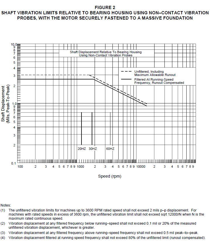
© 2026 Inflection Point Engineering, LLC. All rights reserved. The content of this page — including calculation methods, reference data, written analysis, interactive tools, and source code — is the intellectual property of Inflection Point Engineering, LLC and is protected under applicable copyright, trademark, and trade secret laws. Unauthorized reproduction, redistribution, modification, or derivative use in whole or in part is prohibited without prior written consent.
Disclaimer. This material is provided for informational and educational purposes only and does not constitute professional engineering advice. Calculations, reference data, and methodologies are based on published standards and accepted engineering practice but are not a substitute for engineering judgment, site-specific analysis, or review by a licensed Professional Engineer. Inflection Point Engineering, LLC makes no warranties, express or implied, regarding the accuracy, completeness, or fitness for a particular purpose of any content presented here, and shall not be liable for any direct, indirect, incidental, or consequential damages arising from its use. Users assume all risk associated with applying this content to real-world design, operations, or decisions.
© 2026 Inflection Point Engineering, LLC. All rights reserved.