 Section 13 — Electrical
Equipment Grounding Details
IPE Engineering Practice IPE-EP-13-15-1
Document number: IPE-EP-13-15-1 · Section: 13 — Electrical
SCOPE
- This Practice along with IPE Engineering Practice, provides the recommended design practices for grounding of equipment.
- This Practice shall be applicable to both new facilities and the modernization of existing facilities.
- Any deviation to this Practice shall be in accordance with the procedure given in EP 1–1–3.
- A revision bar indicates all changes made to Revision.
REFERENCES
- The latest published of the NFPA 70 National Electric Code (NEC) shall be the basis for grounding systems. Where there is a conflict between this Practice, IEEE STD 80, IEEE STD 142 and the NEC, the NEC or the more conservative method shall have precedence. For these instances, the conflicts shall be presented to the Owner for resolution. The Owner shall be responsible for approval of all grounding methods that deviate from this Practice.
- The latest edition of the following standards and publications are referred to herein.
STANDARDS & PUBLICATIONS
| IPE Engineering Practices |
|---|
| EP 1–1–3 Deviations to IPE Engineering Practices 480 EP 13–7–1 Volt Prefabricated Switchracks |
| ANSI/IEEE Standards |
| STD 80 Guide for Safety in AC Substation Grounding STD 142 Grounding of Industrial and Commercial Power Systems |
| ASTM |
| D56 Test Method for Flash Point by Tag Closed Tester |
| FIPS |
| FIPS PUB 94 Guideline on Electrical Power for ADP Installations |
| NFPA Standard |
| 70 National Electric Code (NEC) |
DEFINITIONS
- Contractor – Company or business that agrees to furnish materials or perform specified services at a specified price and/or rate to the Owner.
- Inspector – A Inflection Point Engineering, LLC appointed engineer or inspector.
- Manufacturer – The recipient of a direct or indirect purchase order for materials and/or equipment. In this context, a direct order is one issued to a Manufacturer by a Contractor or the Owner. An indirect order is one issued to a Manufacturer by a vendor (recipient of a direct order) for materials, fabricated components, or subassemblies.
- Megger – Shall be used to identify a resistance measurement meter (instrument).
- Owner – Inflection Point Engineering, LLC
- Owner’s Engineer – A Inflection Point Engineering, LLC appointed engineer.
4.0 FIGURES
FIGURE 1 GROUNDING TYPICAL UNIT AREA
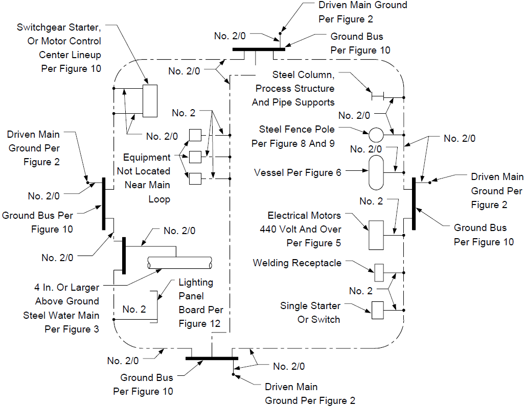
NOTES:
- All underground connections to be by Exothermic Weld Process.
- All above grade equipment and ground bus connections to be by Exothermic Weld Process, one hole straight bar lug, or double hole double crimp compression lug.
- Above diagram is intended as a schematic only. The number of ground rods (minimum of two per ground bus) and ground bus must be determined for each installation.
FIGURE 2 GROUNDING GROUND WELL
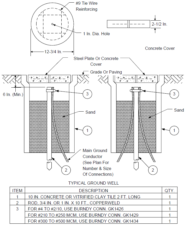
NOTES:
- System ground resistance as measured by a ground megger shall not be greater than 5 ohm’s.
- Covers may be concrete or steel.
FIGURE 3 GROUNDING WATER PIPE
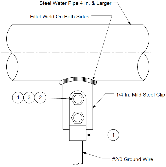
| ITEM | DESCRIPTION | QTY. |
|---|---|---|
| 1 | CADWELD LUG, STRAIGHT BAR. 1 HOLE # 1-20; OR DOUBLE HOLE DOUBLE CRIMP COMPRESSION LUG | 1 |
| 2 | BOLT & NUT, MACH., SILICON BRONZE, 3/8-16 X 1 1/4 IN. | 2 |
| 3 | LOCKWASHER, SILICON BRONZE, 3/8 IN. | 2 |
| 4 | FLATWASHER, SILICON BRONZE, 3/8 IN. | 2 |
NOTES:
1. System ground resistance as measured by a ground megger shall not be greater than 5 ohm’s.
FIGURE 4 GROUNDING TANK
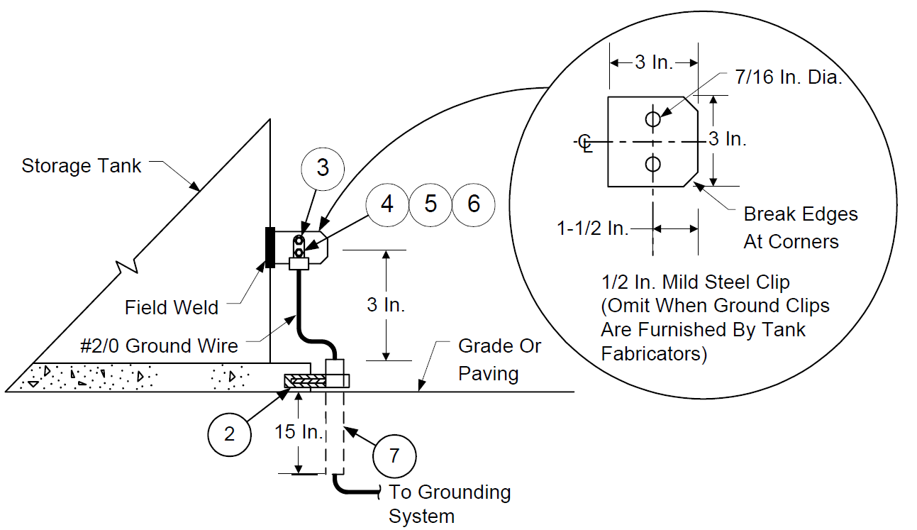
| ITEM | DESCRIPTION | QTY. |
|---|---|---|
| 1 | ONE-HOLE CLAMP W/BACK 3/4 IN. | 1 |
| 2 | 1/4-20 ANCHOR CONCRETE, HILTI | 1 |
| 3 | CADWELD LUG, STRAIGHT BAR, 1 HOLE #-20 OR, DOUBLE HOLE DOUBLE CRIMP COMPRESSION LUG | 1 |
| 4 | BOLT & NUT, MACH., SILICON BRONZE 3/8-16 X 1 1/4 IN. | 2 |
| 5 | LOCKWASHER, SILICON BRONZE, 3/8 IN. | 2 |
| 6 | FLATWASHER, SILICON BRONZE, 3/8 IN. | 2 |
| 7 | CONDUIT, 1 IN. SCHEDULE 80 PVC | 18 IN. |
FIGURE 5 GROUNDING MOTOR
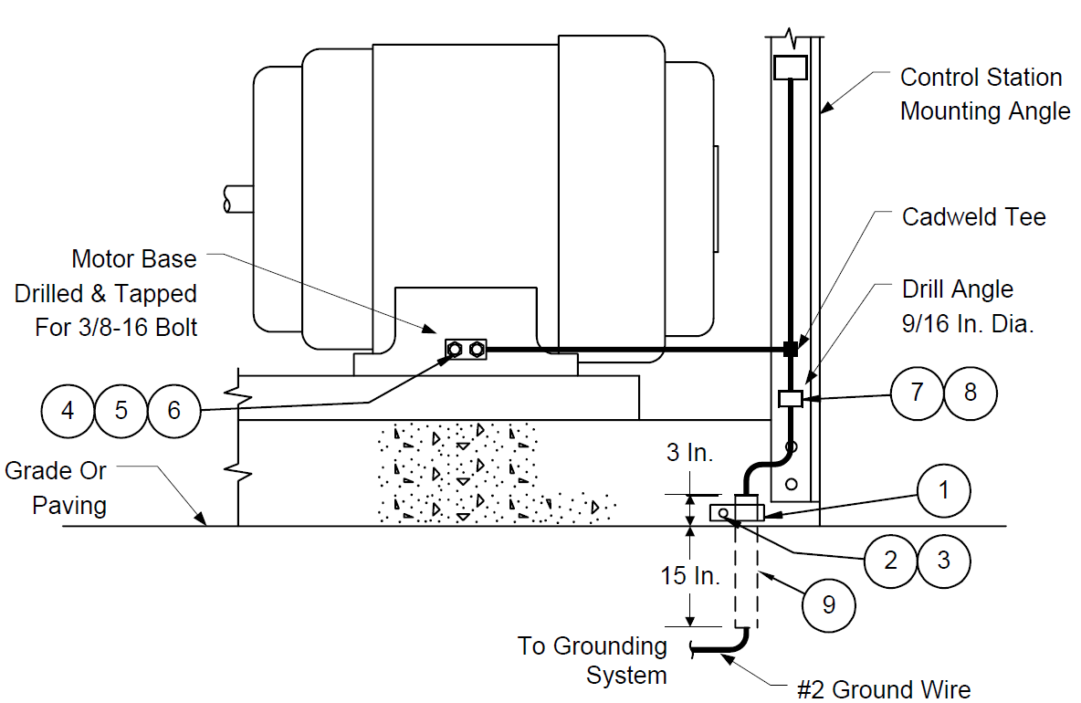
| ITEM | DESCRIPTION | QTY. |
|---|---|---|
| 1 | ONE-HOLE MALEABLE IRON CLAMP W/BACK 3/4 IN. | 1 |
| 2 | 1/4-20 X 1 IN. MACH. BOLT HEX HEAD | 1 |
| 3 | 1/4-20 ANCHOR CONCRETE, HILTI | 1 |
| 4 | SINGLE OR DOUBLE HOLE DOUBLE CRIMP COMPRESSION LUG | 1 |
| 5 | BOLT, MACHINE, 3/8-16 X 1 IN., SILICON BRONZE | 2 |
| 6 | LOCKWASHER, 3/8 IN., SILICON BRONZE | 2 |
| 7 | SERVIT CONNECTOR BURNDY #KC 23 BIN | 1 |
| 8 | LOCKWASHER, 1/2 IN., SILICON BRONZE | 1 |
| 9 | CONDUIT, 1 IN. SCHEDULE 80 PVC | 18 IN. |
FIGURE 6
GROUNDING COLUMN, VESSEL SKIRT, EXCHANGER SADDLE
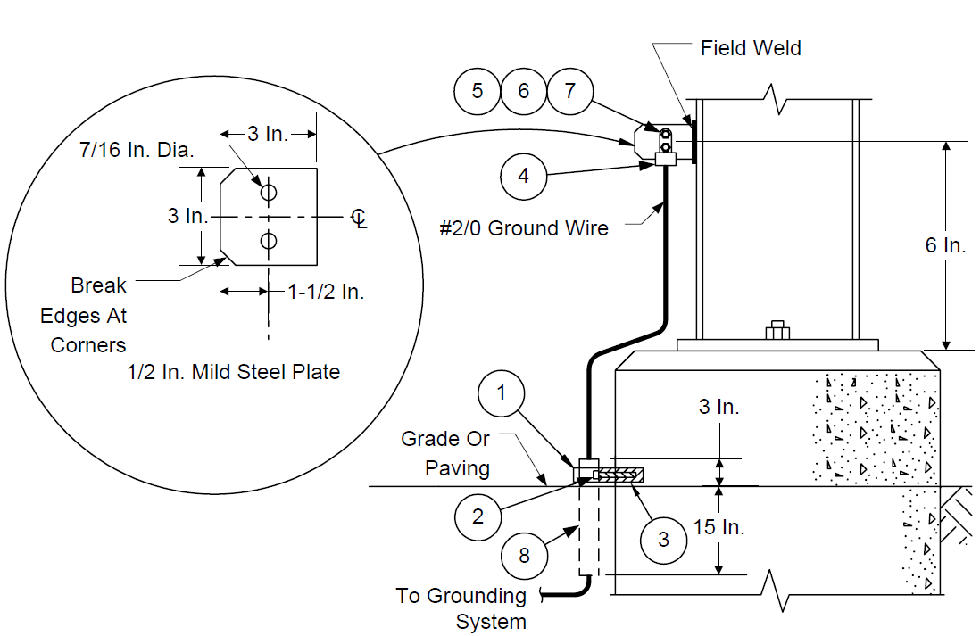
| ITEM | DESCRIPTION | QTY. |
|---|---|---|
| 1 | ONE-HOLE CLAMP W/BACK 3/4 IN. | 1 |
| 2 | 1/4-20 X 1 IN. MACH. BOLT HEX HEAD | 1 |
| 3 | 1/4-20 ANCHOR CONCRETE, HILTI | 1 |
| 4 | DOUBLE HOLE DOUBLE CRIMP COMPRESSION LUG OR CADWELD LUG | 1 |
| 5 | BOLT & NUT, MACH., SILICON BRONZE, 3/8-16 X 1 1/4 IN. | 2 |
| 6 | LOCKWASHER, SILICON BRONZE, 3/8 IN. | 2 |
| 7 | FLATWASHER, SILICON BRONZE, 3/8 IN. | 2 |
| 8 | CONDUIT, 1 IN. SCHEDULE 80 PVC | 18 IN. |
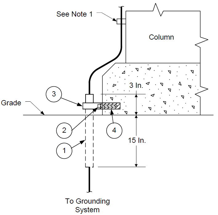
FIGURE 7
GROUNDING FIRE PROOFED COLUMN
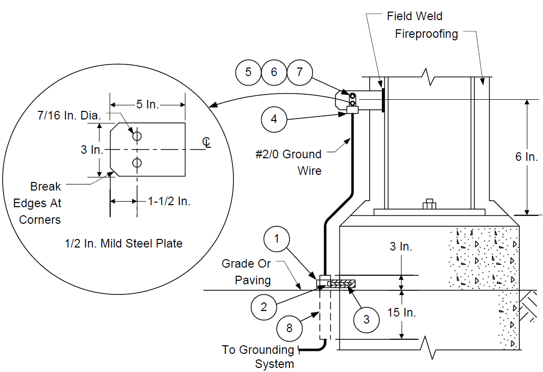
| ITEM | DESCRIPTION | QTY. |
|---|---|---|
| 1 | ONE-HOLE CLAMP W/BACK 3/4 IN. | 1 |
| 2 | 1/4-20 X 1 IN. MACH. BOLT HEX HEAD | 1 |
| 3 | 1/4-20 ANCHOR CONCRETE, HILTI | 1 |
| 4 | DOUBLE HOLE DOUBLE CRIMP COMPRESSION LUG OR CADWELD LUG | 1 |
| 5 | BOLT & NUT, MACH., SILICON BRONZE, 3/8-16 X 1 1/4 IN. | 2 |
| 6 | LOCKWASHER, SILICON BRONZE, 3/8 IN. | 2 |
| 7 | FLATWASHER, SILICON BRONZE, 3/8 IN. | 2 |
| 8 | CONDUIT, 1 IN. SCHEDULE 80 PVC | 18 IN. |
FIGURE 8 GROUNDING FENCE
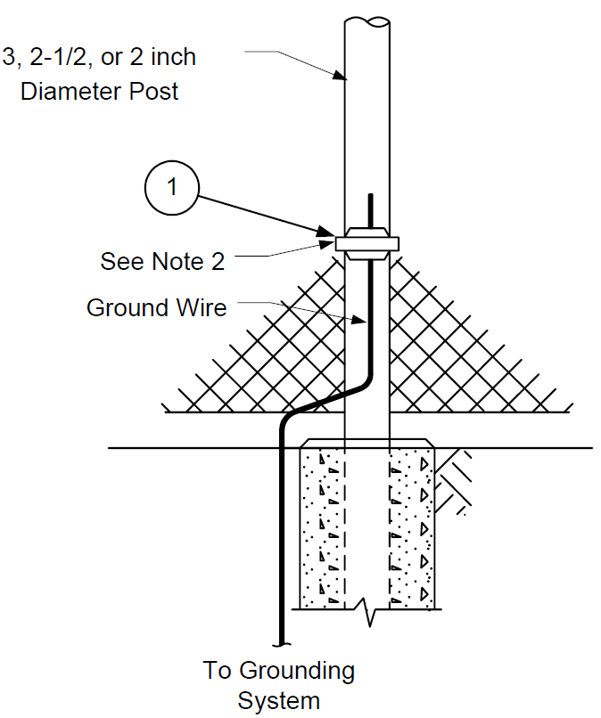
TYPICAL FOR GROUNDING FENCE
| ITEM | DESCRIPTION | QTY. |
|---|---|---|
| 1 SEE NOTE 1 |
3 IN. CONNECTOR BURNDY #GAR-2029-W | 1 |
| 1 SEE NOTE 1 |
2 1/2 IN. CONNECTOR BURNDY #GAR-1929-W | 1 |
| 1 SEE NOTE 1 |
2 IN. CONNECTOR BURNDY #GAR-1829-W | 1 |
NOTES:
- Grounding connector type, according to size of post.
- All grounding connectors, tin plated.
FIGURE 9 GROUNDING FENCE GATE
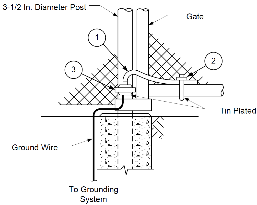
TYPICAL FOR GROUNDING FENCE GATE
| ITEM | DESCRIPTION | QTY. |
|---|---|---|
| 1 | FLEXIBLE COPPER BRAID, BURNDY-BD12W | 1 |
| 2 | CONNECTOR, BURNDY #GG17-1-W | 1 |
| 3 | CONNECTOR, BURNDY #GAR-2129-W | 1 |
FIGURE 10 GROUNDING TEST BUS BAR
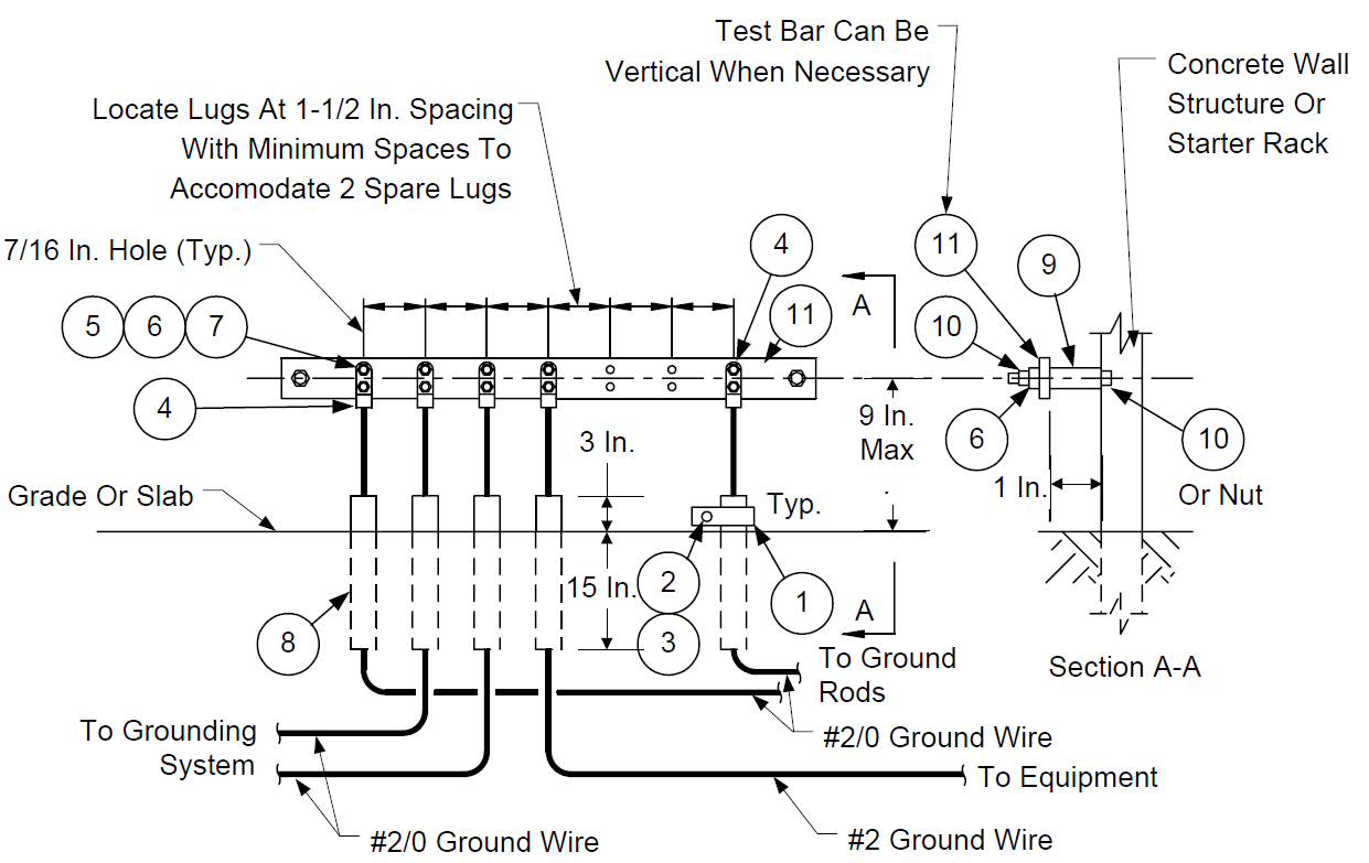
| ITEM | DESCRIPTION | QTY. |
|---|---|---|
| 1 | MALEABLE IRON ONE-HOLE CLAMP W/BACK 3/4 IN. | |
| 2 | 1/4-20 X 1 IN. MACH. BOLT HEX HEAD | |
| 3 | 1/4-20 ANCHOR CONCRETE, HILTI | |
| 4 | DOUBLE HOLE DOUBLE CRIMP COMPRESSION LUG | |
| 5 | BOLT & NUT, MACH., SILICON BRONZE, 3/8-16 X 1 1/4 IN. | |
| 6 | LOCKWASHER, SILICON BRONZE, 3/8 IN. | |
| 7 | FLATWASHER, SILICON BRONZE, 3/8 IN. | |
| 8 | CONDUIT, 1 IN. SCHEDULE 80 PVC (18 IN. LONG EACH) | |
| 9 | CONCRETE ANCHOR, 3/8-16, HILTI | |
| 10 | BOLT & NUT, MACH., S.S., 3/8-16 X 2 IN. | |
| 11 | 1/4 IN. X 2 IN. COPPER BAR |
FIGURE 11
GROUNDING TRANSFORMER & LIGHTING PANEL
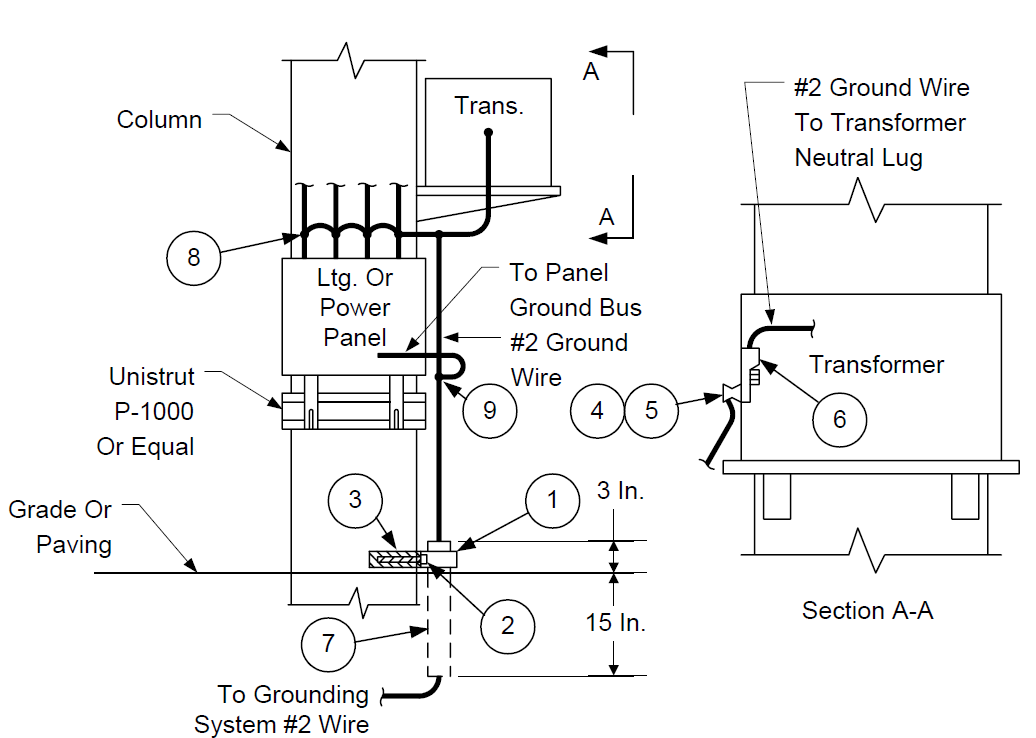
| ITEM | DESCRIPTION | QTY. |
|---|---|---|
| 1 | ONE-HOLE CLAMP W/BACK 3/4 IN. | 1 |
| 2 | 1/4-20 X 1 IN. MACH. BOLT HEX HEAD | 1 |
| 3 | 1/4-20 ANCHOR CONCRETE, HILTI | 1 |
| 4 | SERVIT CONNECTOR BURNDY #KC 23 BIN | 1 |
| 5 | LOCKWASHER, SILICON BRONZE, 3/8 IN. | 1 |
| 6 | SINGLE HOLE DOUBLE CRIMP COMPRESSION LUG | 1 |
| 7 | CONDUIT, 1 IN. SCHEDULE 80 PVC | 18 IN. |
| 8 | GROUNDING CLAMP , TYPICAL BURNDY GAR | |
| 9 | EXOTHERMIC CADWELD CONNECTION | 1 |
NOTES:
1. Support grounding conductor above grade every 4 ft. with cable clamp Appleton SECL–IU or equal.
FIGURE 12
GROUNDING MISCELLANEOUS EQUIPMENT
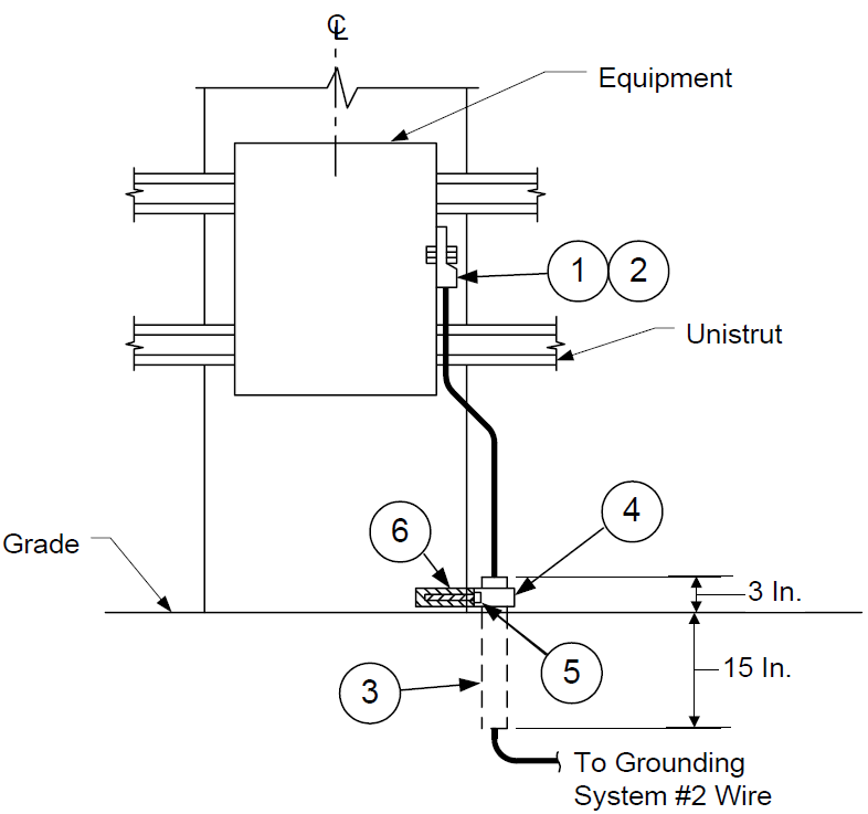
| ITEM | DESCRIPTION | QTY. |
|---|---|---|
| 1 | SINGLE HOLE DOUBLE CRIMP COMPRESSION LUG | 1 |
| 2 | MACH. BOLT & NUT, S.S., 3/8 IN. | 1 |
| 3 | CONDUIT, 1 IN. SCHEDULE 80 PVC | 18 IN. |
| 4 | ONE-HOLE CLAMP W/BACK 3/4 IN. | 1 |
| 5 | 1/4-20 X 1 IN. MACH. BOLT HEX HEAD | 1 |
| 6 | 1/4-20 ANCHOR CONCRETE, HILTI | 1 |
FIGURE 13 GROUNDING GROUND WIRE SLEEVE
| ITEM | DESCRIPTION | QTY. |
|---|---|---|
| 1 | CONDUIT, 1 IN. SCHEDULE 80 PVC | 18 IN. |
| 2 | 1/4-20 X 1 IN. MACH. BOLT HEX HEAD | 1 |
| 3 | ONE-HOLE CLAMP W/BACK 3/4 IN. | 1 |
| 4 | 1/4-20 ANCHOR CONCRETE, HILTI | 1 |
NOTES:
1. Provide cable supports spaced not more than 4 ft. center to center.
FIGURE 14 GROUNDING TANK TRUCK
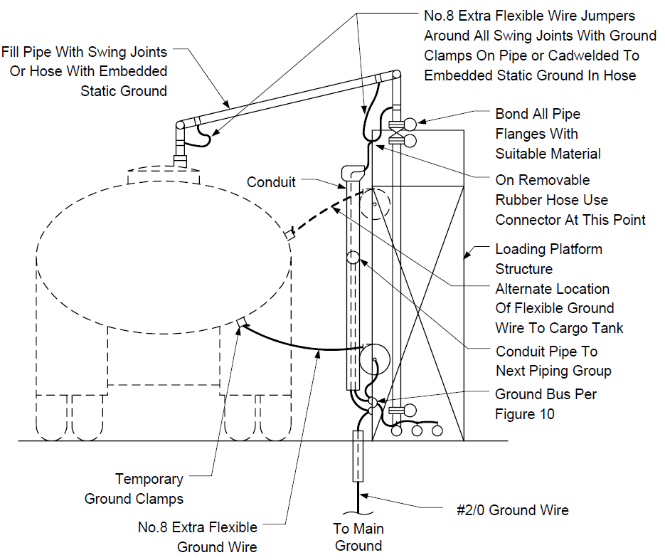
NOTES:
- Ground systems, In accordance with this Standard, shall be installed on all loading racks and unloading racks dispensing or receiving:
- Flammable liquid (defined as; materials or mixtures with a flash point 200F or less by ASTM test D–56: such as, gasoline, naphtha, furnace oil, diesel oil, fuel oil);
- Asphalt;
- Liquefied flammable gas (defined as: materials or mixtures with a Keld vapor pressure in excess of 40 psia at 100F which will form a flammable mixture when mixed in the proportion of 13% or less by volume with air; such as, butane, propane, hydrogen sulfide, acetylene, etc);
- All ground wires to be stranded bare copper wire of size indicated.
- All ground wires above grade to be extra flexible.
- Provide ground interlock system when specified by the Owner.
FIGURE 15
GROUNDING TANK CAR LOADING AND UNLOADING
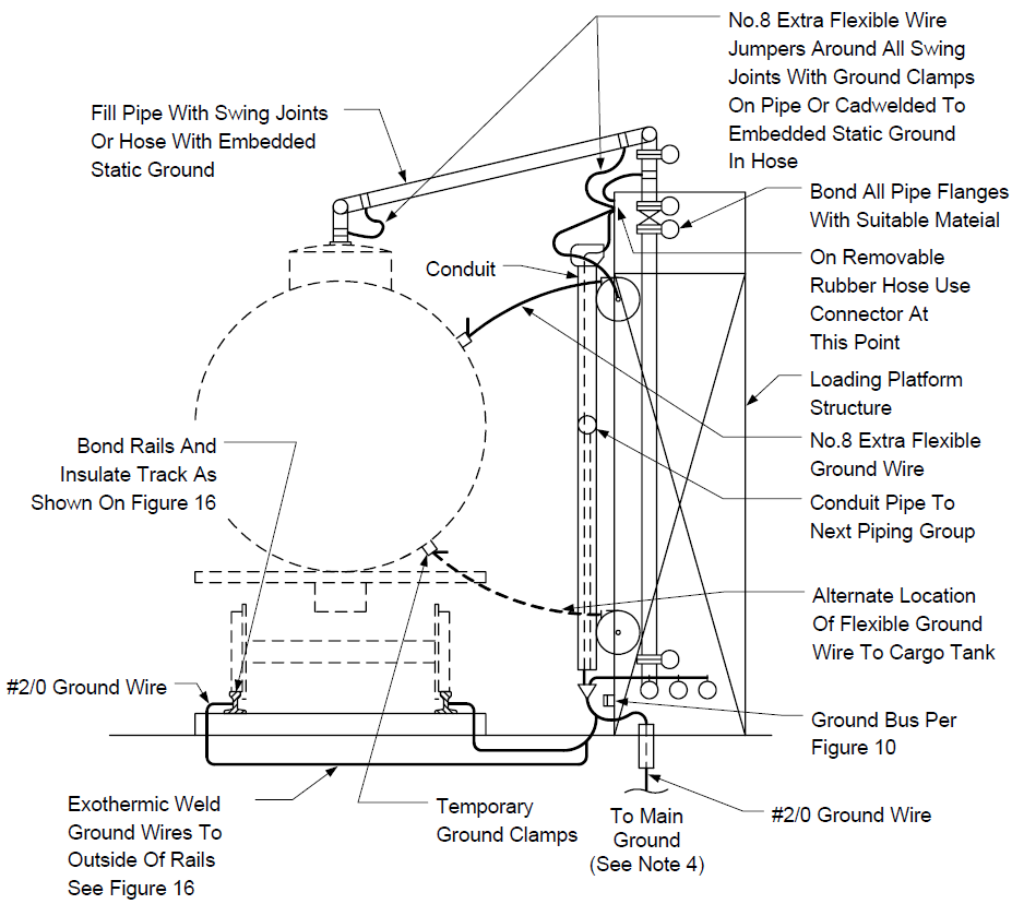
NOTES:
- Ground systems, in accordance with this Standard, shall be installed on all loading racks and unloading racks dispensing or receiving:
- Flammable liquid (defined as; materials or mixtures with a flash point 200F or less by ASTM test D–56: such as, gasoline, naphtha, furnace oil, diesel oil, fuel oil);
- Asphalt;
- Liquefied flammable gas (defined as: materials or mixtures with a Keld vapor pressure in excess of 40 psia at 100F which will form a flammable mixture when mixed in the proportion of 13% or less by volume with air; such as, butane, propane, hydrogen sulfide, acetylene, etc.);
- All ground wires to be stranded bare copper wire of size indicated.
- All ground wires above grade to be extra flexible.
- Provide ground interlock system when specified by the Owner.
FIGURE 16 GROUNDING TANK CAR TRACK RAIL
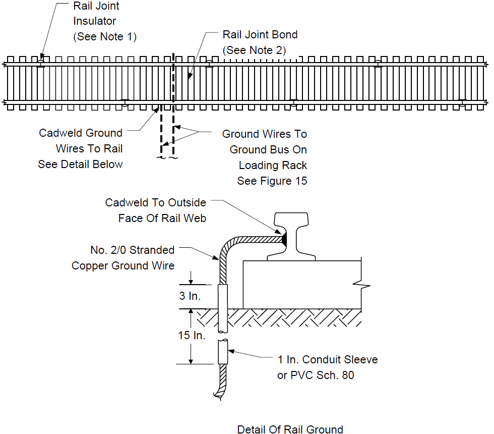
NOTES:
- Install insulated rail joints between track section on which tank cars will be loaded or unloaded and all other track rails.
- Install rail bonds on track section on which tank cars will be loaded or unloaded. Use No. 2 copper stranded ground wire and Cadweld to outside surface of rail.
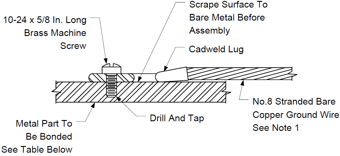
FIGURE 17
GROUNDING FLOATING ROOFS ON TANKS
| ROOF PART | TYPICAL DETAIL (SEE NOTE 2) |
WHEN BONDED |
|---|---|---|
| LADDER | FIGURE 18 | ALWAYS |
| MANGERS, ABOVE DECK ONLY | FIGURE 18 | WHEN RESISTANCE TO SHELL MEASURES OVER 3000 OHMS |
| GUIDE DEVICES | FIGURE 19 | WHEN RESISTANCE TO SHELL MEASURES OVER 3000 OHMS |
| COVERS (RIM VENT, AUTOMATIC FLOAT GAGE WELL, GAGE HATCH, MANHOLE AND HAND HOLE, AUTOMATIC FLOAT GAGE SHEAVE, MAIN DRAIN, AND EMERGENCY DRAIN) |
FIGURE 20 | WHEN RESISTANCE TO SHELL MEASURES OVER 3000 OHMS |
| AUTOMATIC BLEEDER VENT | FIGURE 19 | WHEN RESISTANCE TO SHELL MEASURES OVER 3000 OHMS |
| ROOF SUPPORTS | FIGURE 19 | WHEN RESISTANCE TO SHELL MEASURES OVER 3000 OHMS |
| FOAM CHAMBER BACKBOARD (BOLTED TYPE) | FIGURE 19 | WHEN RESISTANCE TO SHELL MEASURES OVER 3000 OHMS |
NOTES:
- Bond wires shall be long enough to allow normal movement of the part being bonded. For example, bonds for covers shall permit the covers to be removed and laid on the roof deck; and bonds for roof supports and automatic bleeder vents shall permit adjustment between high and low positions.
- The bonding of specific items is typical rather than exact detail. The object is to make a reliable electrical connection between the part being bonded and an adjacent part which is welded to the roof structure.
FIGURE 18
GROUNDING FLOATING ROOFS ON TANKS
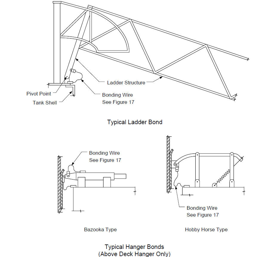
FIGURE 19
GROUNDING FLOATING ROOFS ON TANKS
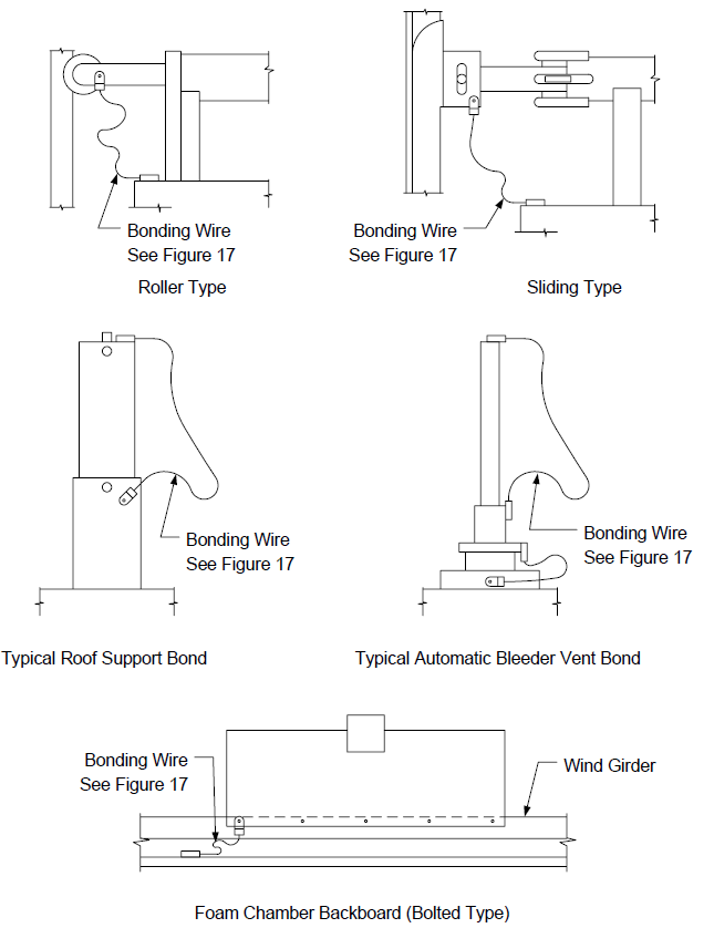
FIGURE 20
GROUNDING FLOATING ROOFS ON TANKS
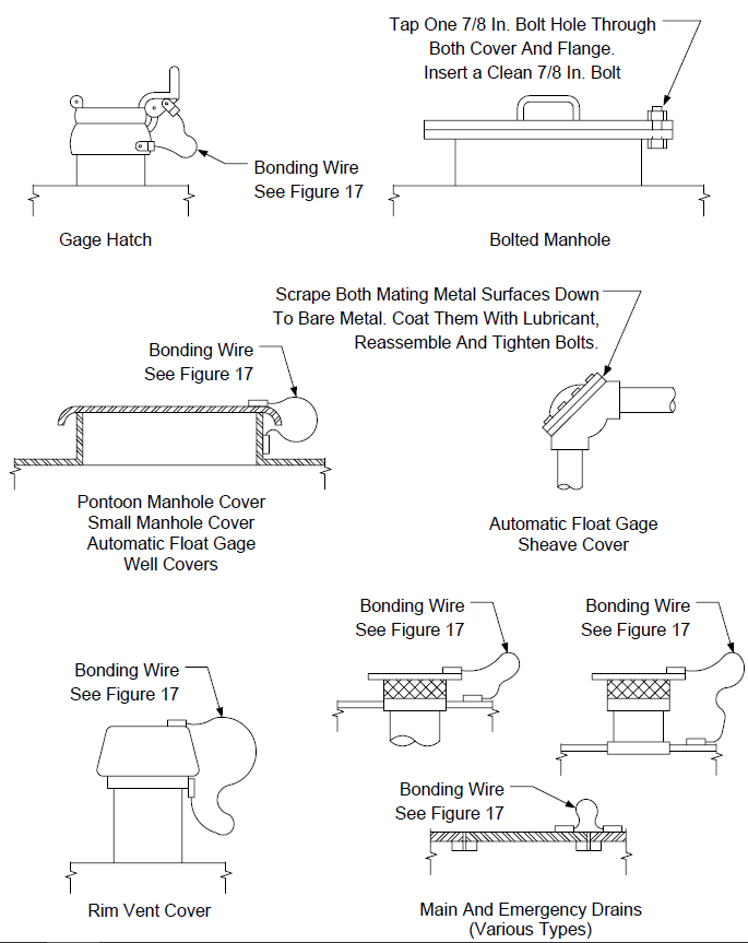
FIGURE 21
GROUNDING POWER POLE (BUTT GROUND)
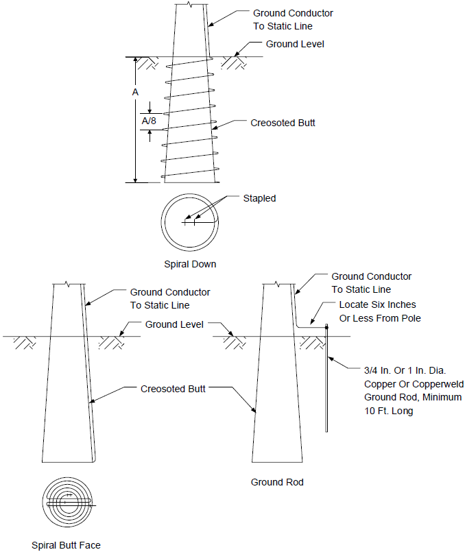
FIGURE 22
“SINGLE POINT” GROUNDING SYSTEM USED WITH COMPUTER/DCS
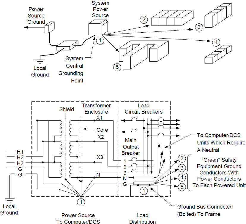
FIGURE 23
“SINGLE POINT” GROUNDING SYSTEM AND ZERO SIGNAL REFERENCE GRID
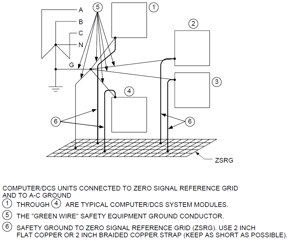
NOTE: Any metallic non-current–carrying objects which pass through the ZSRG (e.g. conduit, floor posts, heating ducts, etc) must be bonded to the ZSRG.
FIGURE 24
ZERO SIGNAL REFERENCE GRID CONSTRUCTION
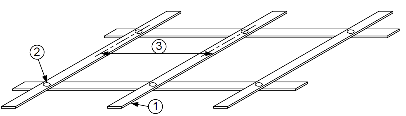
NOTES:
- Grid material shall be 16 AWG copper strap 0.051 inches by 2 inches.
- Cross points shall be connected with exothermic welds.
- Grid mesh spacing shall be 2 feet maximum weld to weld.
FIGURE 25
SINGLE POINT GROUNDING, ZERO SIGNAL REFERENCE GRID
AND DCS RACKS WITH ISOLATED PRIMARY/BACKUP POWER SOURCES
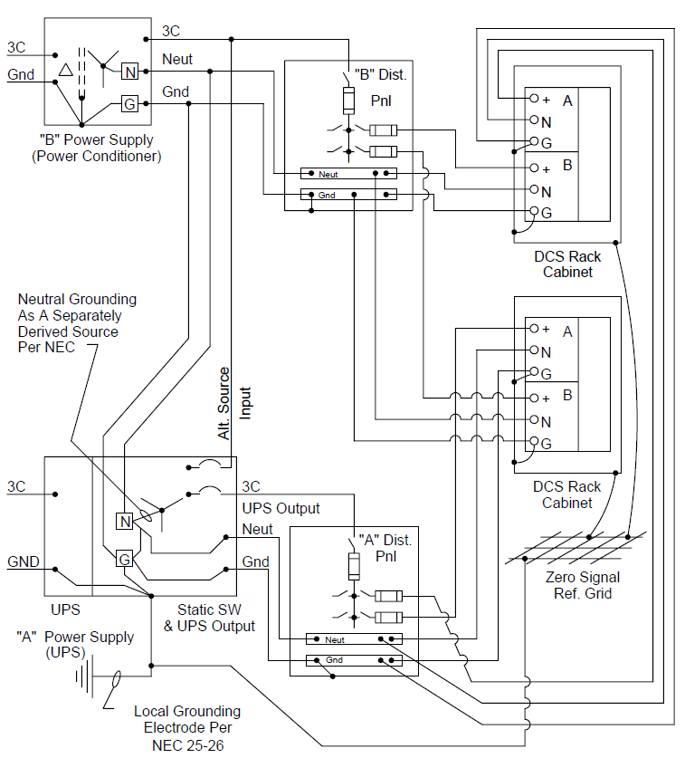
NOTES:
- “A” or “B” power supplies could be a UPS, power conditioner, Isolation transformer, etc.
- ZSRG shall be used for equipment with a process rate 10 mHz and higher. For equipment with process rates 3 to 10 mHz, individual evaluation with equipment manufacturer shall determine the requirements.
FIGURE 26
TYPICAL GROUNDING OF 480 VOLT SWITCHRACKS AND ENCLOSURES (EQUIPMENT)
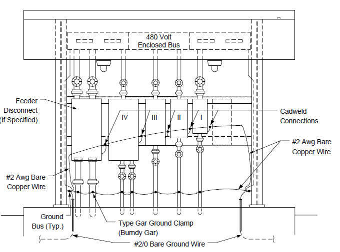
NOTES:
- Ground all equipment enclosures mounted on the switchrack with #2 AWG, or larger, stranded copper wire and crimp lugs secured at an enclosure (equipment) mounting foot.
- Refer to EP 13–7–1 for additional details.
© 2026 Inflection Point Engineering, LLC. All rights reserved. The content of this page — including calculation methods, reference data, written analysis, interactive tools, and source code — is the intellectual property of Inflection Point Engineering, LLC and is protected under applicable copyright, trademark, and trade secret laws. Unauthorized reproduction, redistribution, modification, or derivative use in whole or in part is prohibited without prior written consent.
Disclaimer. This material is provided for informational and educational purposes only and does not constitute professional engineering advice. Calculations, reference data, and methodologies are based on published standards and accepted engineering practice but are not a substitute for engineering judgment, site-specific analysis, or review by a licensed Professional Engineer. Inflection Point Engineering, LLC makes no warranties, express or implied, regarding the accuracy, completeness, or fitness for a particular purpose of any content presented here, and shall not be liable for any direct, indirect, incidental, or consequential damages arising from its use. Users assume all risk associated with applying this content to real-world design, operations, or decisions.
© 2026 Inflection Point Engineering, LLC. All rights reserved.