 Section 12 — Instruments and Controls
Control Systems Installation
IPE Engineering Practice IPE-EP-12-2-1
Document number: IPE-EP-12-2-1 · Section: 12 — Instruments and Controls
1.0 SCOPE 5
2.0 REFERENCES 5
3.0 DEFINITIONS 5
4.0 FIGURES 6
Figure 1 Typical Connection For Non Arc–Producing Instrument, Meeting Area Classification 6
Figure 2 Instrument Support Dual Pedestal For Paved Area 7
Figure 3 Instrument Support Single Pedestal For Paved Area 8
Figure 4 Instrument Support Dual Pedestal Outside Platform 9
Figure 5 Pneumatic Piping Trans. Controller & Va. W/Positioner 10
Figure 6 Tubeskin Thermocouple Installation Detail Radiant Section Mounting 11
Figure 7 Tubeskin Thermocouple Installation Details Axial Mounting Details 12
Figure 8 Tubeskin Thermocouple Installation Detail Transverse Mounting Details 13
Figure 9 Tubeskin Thermocouple Installation Detail Welding Detail 14
Figure 10 Tubeskin Thermocouple Installation Detail Convection Section 15
Figure 11 Tubeskin Thermocouple Installation Detail Furnace Wall Entry 16
Figure 12 Pressure Gauges Tap Mounting 17
Figure 13 Instrument Piping Pressure Transmitter Gas Service
(Transmitter Below Process Tap) 18
Figure 14 Instrument Piping Press. Trans. W/Press. Gauge Steam Or Liquid Service 19
Figure 15 Instrument Piping Pressure Switch Liquid Service 20
Figure 16 Instrument Piping Pressure Indicating Controller Gas Service 21
Figure 17 Instrument Piping Remote Mounted Pressure Instr. (Steam Traced) 22
Figure 18 Instrument Piping Pressure Switch With Gauge (Gas Service) 23
Figure 19 Instrument Piping Differential Pressure Transmitter (Gas Service) 24
Figure 20 Instrument Piping Pressure Gauge (Board Mounted) 25
Figure 21 Instrument Piping Gas Service Pressure Transmitter W/ Flow Orifice & Rotameter 26
Figure 22 Instrument Piping Pressure Transmitter - Steam Or Liquid Service 27
Figure 23 Instrument Piping Pressure Transmitter - Gas Service (Preferred Installation) 28
Figure 24 Instrument Piping Differential Instrument Bellows Type - Close Coupled 29
Figure 25 Instrument Piping Flow D/P Cell Vertical Line Air Or Gas 30
Figure 26 Instrument Piping Flow D/P Cell Vertical Line Liquid Or Steam Service 31
Figure 27 Instrument Piping Flow D/P Cell Bellows - Switch Common Tap 32
Figure 28 Instrument Piping Flow D/P Cell Horizontal Line Air Or Gas 33
Figure 29 Instrument Piping Bellows Type Flow Indicator Liquid Service 34
Figure 30 Instrument Piping Flow D/P Cell - Horizontal Line Liquid Or Steam 35
Figure 31 Typical Connection For Arc–Producing Instrument (Level Switch Float
Switch Pressure Switch Etc) 36
Figure 32 Instrument Piping Level D/P Cell Wet Leg Installation 37
Figure 33 Pneumatic Piping Level Trans. W/Switch & Control Valve With Positioner 38
Figure 34 Pneumatic Piping Level Transmitter With Switch And Transducer 39
Figure 35 Instrument Piping Capacitance Level Switch 40
Figure 36 Instrument Piping Diff. Press. Indicator & Gauge Gas Service 41
Figure 37 Pneumatic Piping 3–Way Valve W/ Manual Reset To Control Valve 42
Figure 38 Instrument Drawing Diaphragm Actuator Piping 43
Figure 39 Instrument Drawing Installation Details Liquid Level Controllers And Gauges 44
Figure 40 Instrument Drawing Installation Details: Liquid Level Controllers And Gauges 45
SCOPE
The following Figures shall be used for instrument installation. Related Practices for these instruments are described in EP 12–1–1 and EP 5–6–5. The contractor shall not attempt to interpret the Owner’s requirements in any installation standard that is not clear, or appears to conflict with any other Practices, or omits something. The contractor shall request an interpretation or answer from the Owner’s Engineer before proceeding.
- Any deviation from this Practice must be approved using the procedure described in EP 1–1–3.
2.0 REFERENCES
The latest edition of the following standards and publications are referred to herein, and shall be used with this Practice.
STANDARDS AND PUBLICATIONS
DEFINITIONS
- Contractor - Company or business that agrees to furnish materials or perform specified services at a specified price and/or rate to the Owner.
- Owner - Inflection Point Engineering, LLC.
- Owner’s Engineer - A Inflection Point Engineering, LLC appointed engineer.
4.0 FIGURES
FIGURE 1 TYPICAL CONNECTION FOR NON ARC–PRODUCING INSTRUMENT, MEETING AREA CLASSIFICATION
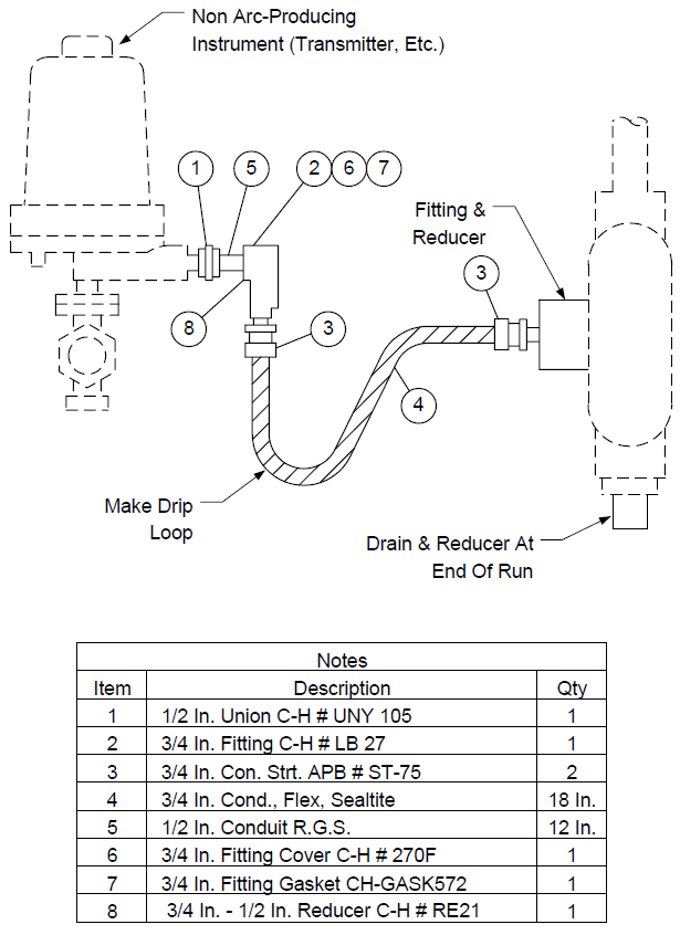
FIGURE 2 INSTRUMENT SUPPORTDUAL PEDESTAL FOR PAVED AREA
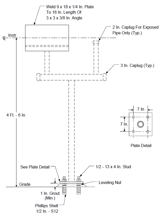
FIGURE 3
INSTRUMENT SUPPORT SINGLE PEDESTAL FOR PAVED AREA
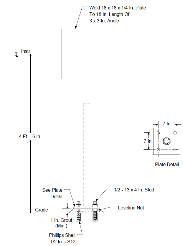
FIGURE 4 INSTRUMENT SUPPORT DUAL PEDESTAL OUTSIDE PLATFORM
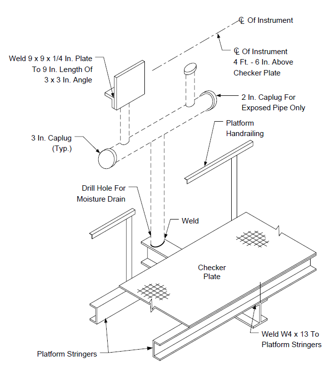
FIGURE 5
PNEUMATIC PIPING TRANS. CONTROLLER & VA. W/POSITIONER
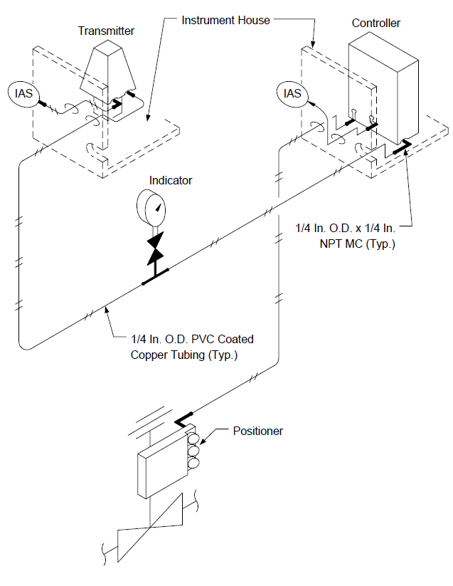
FIGURE 6
TUBESKIN THERMOCOUPLE INSTALLATION DETAIL RADIANT SECTION MOUNTING
Typical Transverse Mounted Thermocouple With Expansion Loop
Typical Axial Mounted Thermocouple
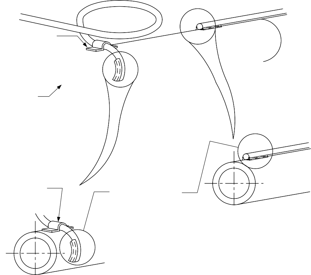
Detail A
Typical Transverse Installation
NOTES:
- Shield sheath from radiant effects by running “behind” tube.
- Use of pad mounted thermocouples not acceptable.
FIGURE 7
TUBESKIN THERMOCOUPLE INSTALLATION DETAILS AXIAL MOUNTING DETAILS
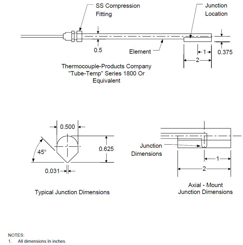
FIGURE 8
TUBESKIN THERMOCOUPLE INSTALLATION DETAIL TRANSVERSE MOUNTING DETAILS
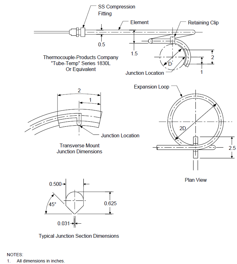
FIGURE 9
TUBESKIN THERMOCOUPLE INSTALLATION DETAIL WELDING DETAIL
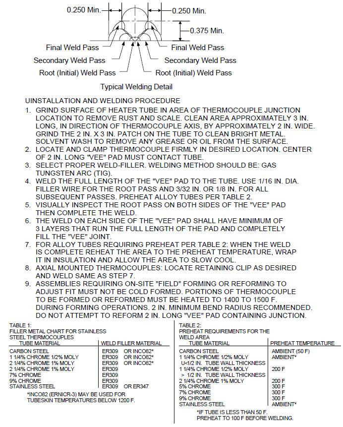
FIGURE 10
TUBESKIN THERMOCOUPLE INSTALLATION DETAIL CONVECTION SECTION
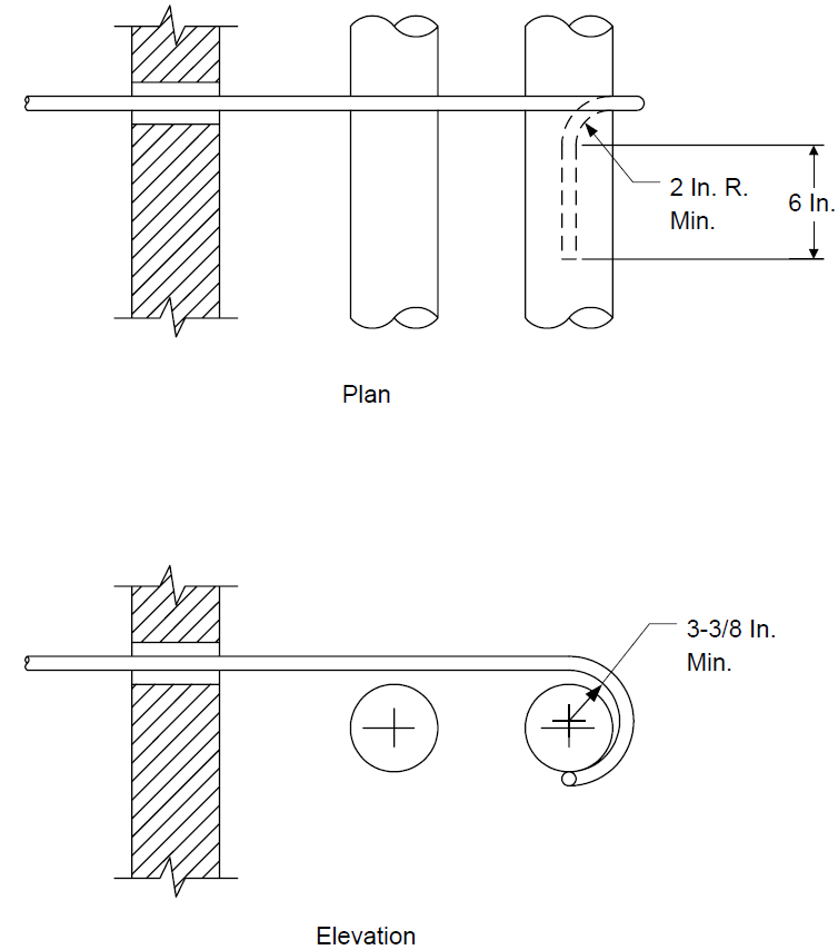
FIGURE 11
TUBESKIN THERMOCOUPLE INSTALLATION DETAIL FURNACE WALL ENTRY
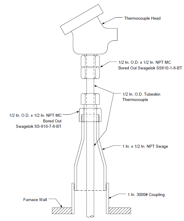
FIGURE 12 PRESSURE GAUGES TAP MOUNTING
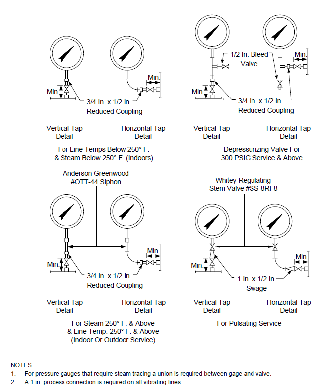
FIGURE 13 INSTRUMENT PIPING PRESSURE TRANSMITTER GAS SERVICE (TRANSMITTER BELOW PROCESS TAP)
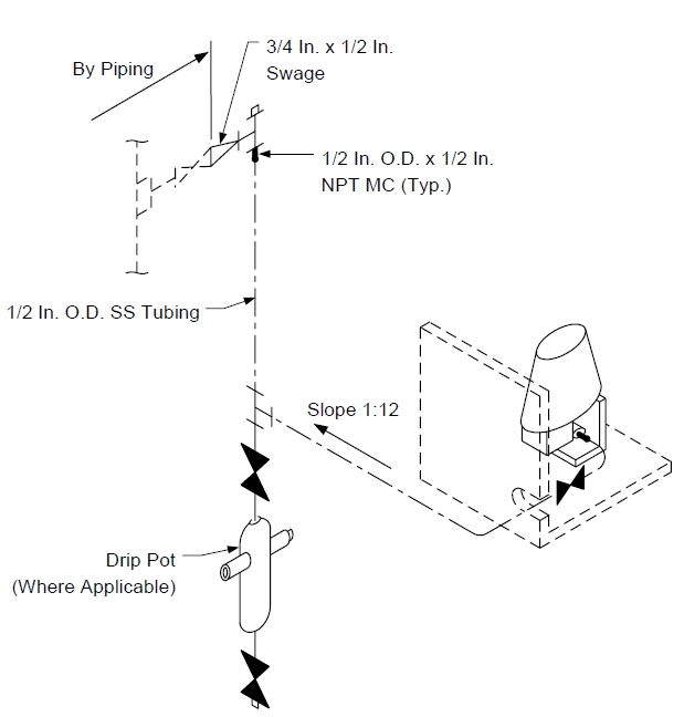
FIGURE 14
INSTRUMENT PIPING PRESS. TRANS. W/PRESS. GAUGE STEAM OR LIQUID SERVICE
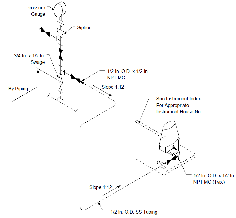
FIGURE 15
INSTRUMENT PIPING PRESSURE SWITCH LIQUID SERVICE
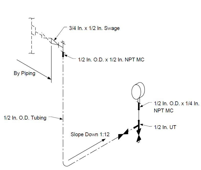
FIGURE 16 INSTRUMENT PIPING PRESSURE INDICATING CONTROLLER GAS SERVICE
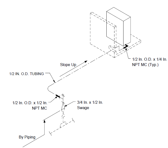
FIGURE 17 INSTRUMENT PIPING REMOTE MOUNTED PRESSURE INSTR. (STEAM TRACED)
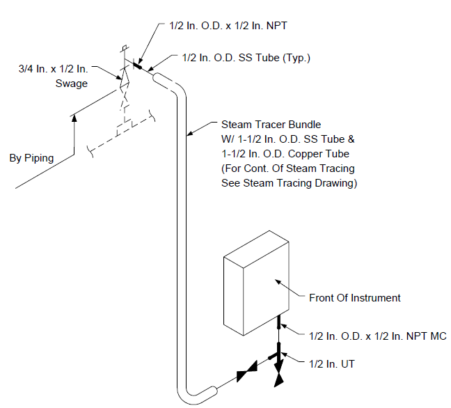
FIGURE 18
INSTRUMENT PIPING PRESSURE SWITCH WITH GAUGE (GAS SERVICE)
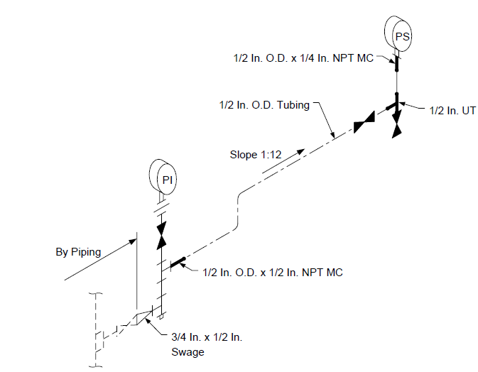
FIGURE 19 INSTRUMENT PIPING DIFFERENTIAL PRESSURE TRANSMITTER (GAS SERVICE)
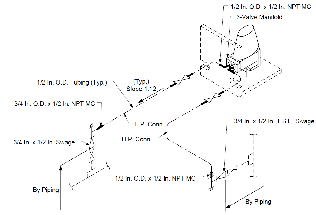
FIGURE 20
INSTRUMENT PIPING PRESSURE GAUGE (BOARD MOUNTED)
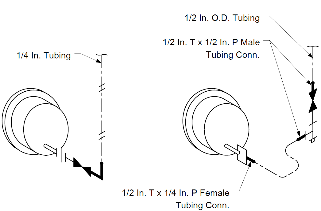
FIGURE 21
INSTRUMENT PIPING GAS SERVICE PRESSURE TRANSMITTER W/ FLOW ORIFICE & ROTAMETER
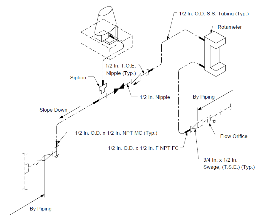
FIGURE 22 INSTRUMENT PIPING PRESSURE TRANSMITTER - STEAM OR LIQUID SERVICE
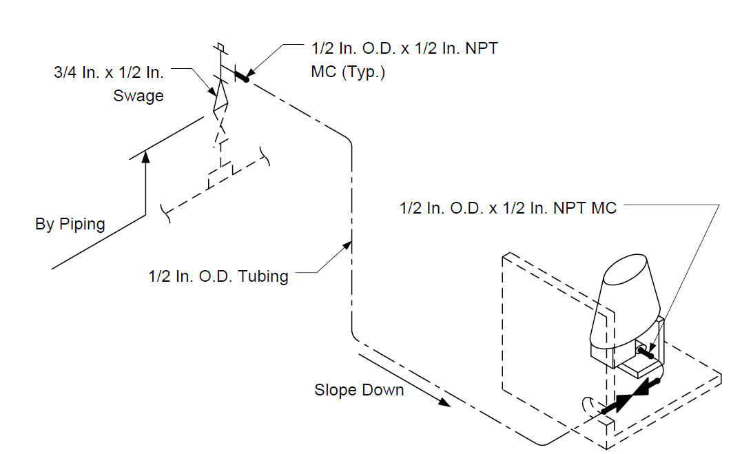
FIGURE 23 INSTRUMENT PIPING PRESSURE TRANSMITTER - GAS SERVICE (PREFERRED INSTALLATION)
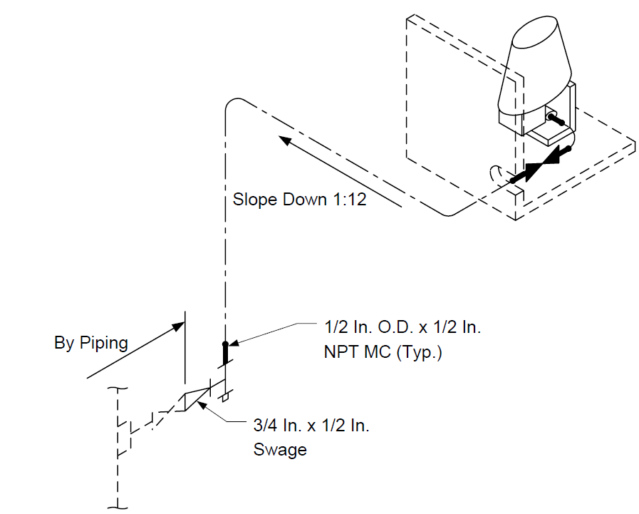
FIGURE 24
INSTRUMENT PIPING DIFFERENTIAL INSTRUMENT BELLOWS TYPE - CLOSE COUPLED

FIGURE 25
INSTRUMENT PIPING FLOW D/P CELL VERTICAL LINE AIR OR GAS
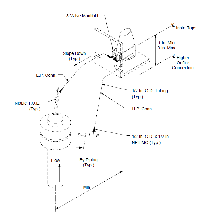
FIGURE 26
INSTRUMENT PIPING FLOW D/P CELL VERTICAL LINE LIQUID OR STEAM SERVICE
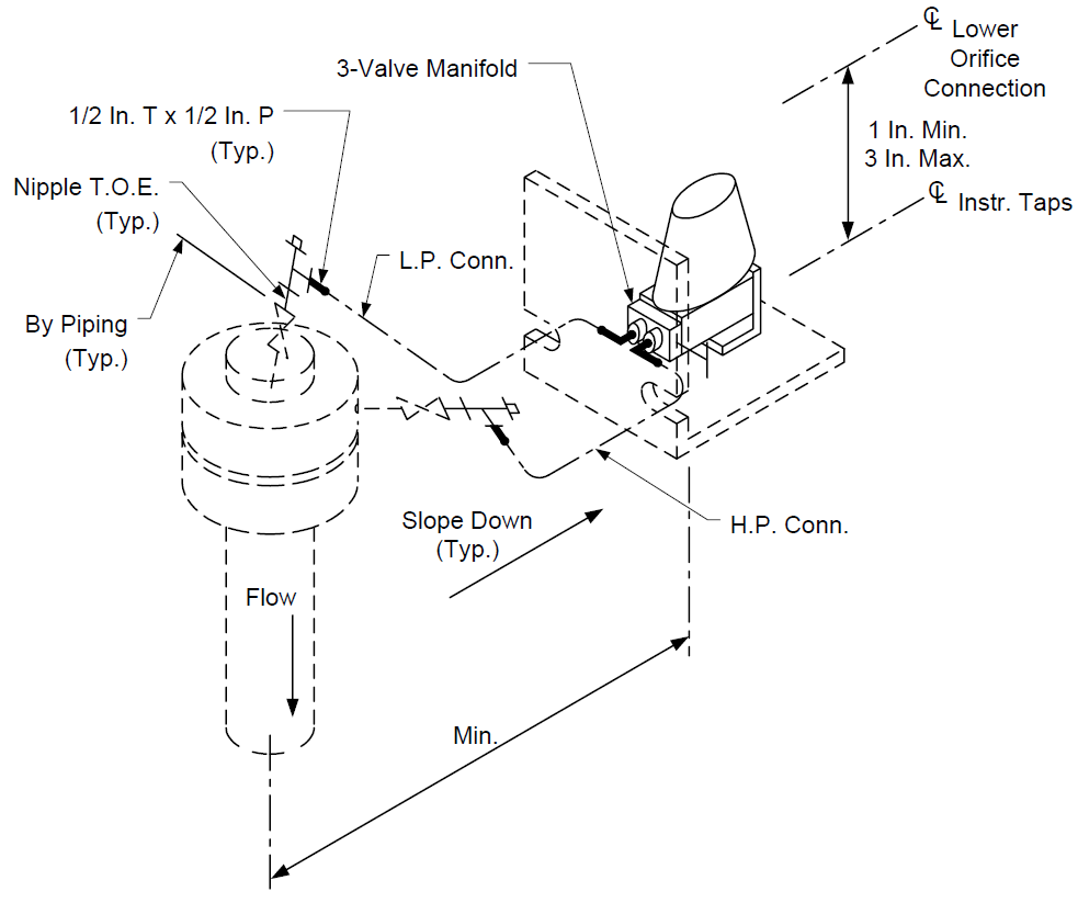
FIGURE 27
INSTRUMENT PIPING FLOW D/P CELL BELLOWS - SWITCH COMMON TAP
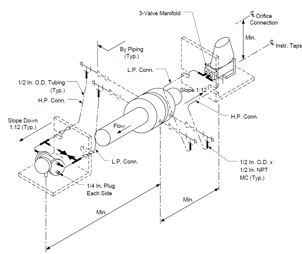
FIGURE 28
INSTRUMENT PIPING FLOW D/P CELL HORIZONTAL LINE AIR OR GAS
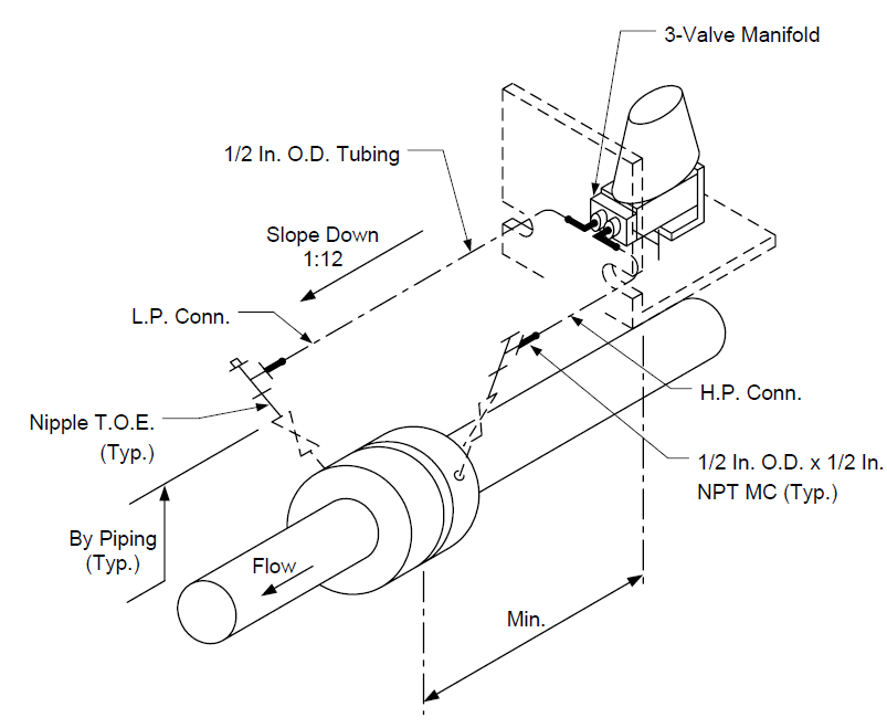
FIGURE 29
INSTRUMENT PIPING BELLOWS TYPE FLOW INDICATOR LIQUID SERVICE
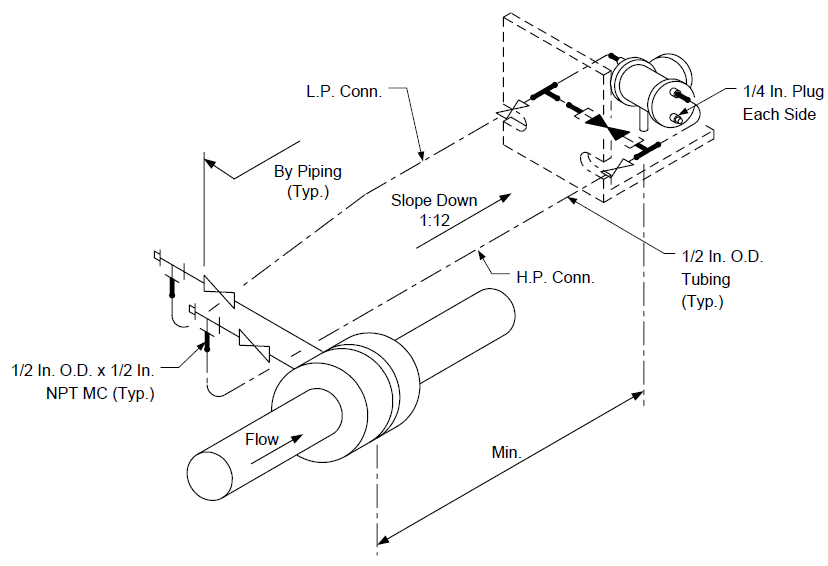
FIGURE 30
INSTRUMENT PIPING FLOW D/P CELL - HORIZONTAL LINE LIQUID OR STEAM
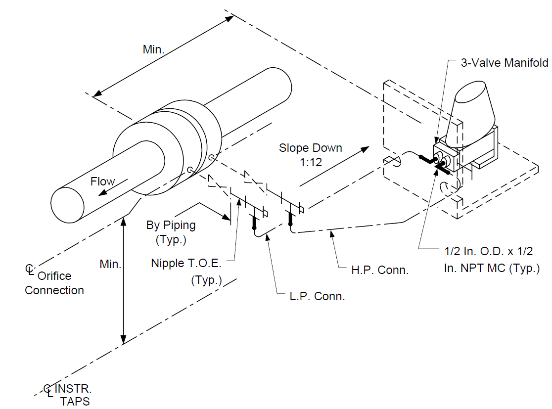
FIGURE 31
TYPICAL CONNECTION FOR ARC–PRODUCING INSTRUMENT (LEVEL SWITCH FLOAT SWITCH PRESSURE SWITCH ETC)
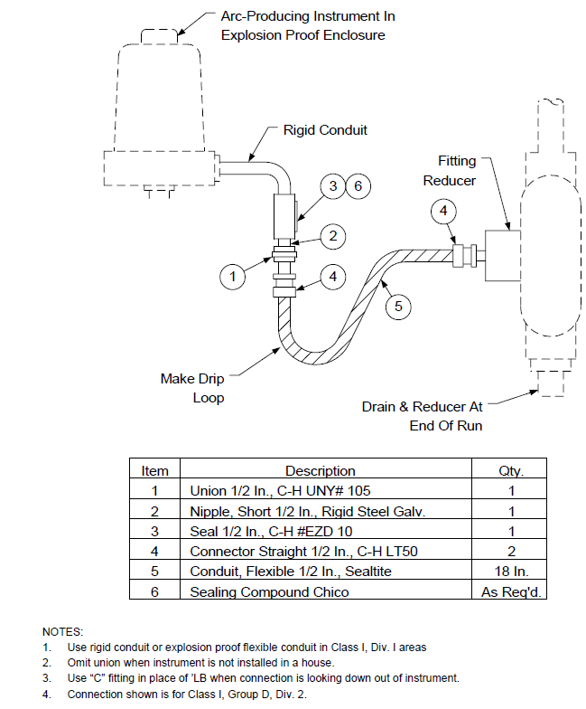
FIGURE 32
INSTRUMENT PIPING LEVEL D/P CELL WET LEG INSTALLATION
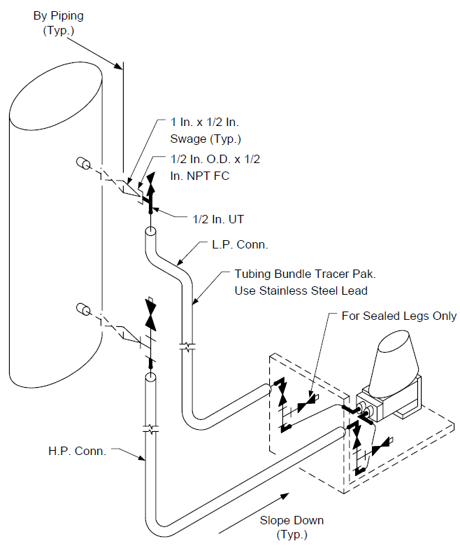
FIGURE 33
PNEUMATIC PIPING LEVEL TRANS. W/SWITCH & CONTROL VALVE WITH POSITIONER
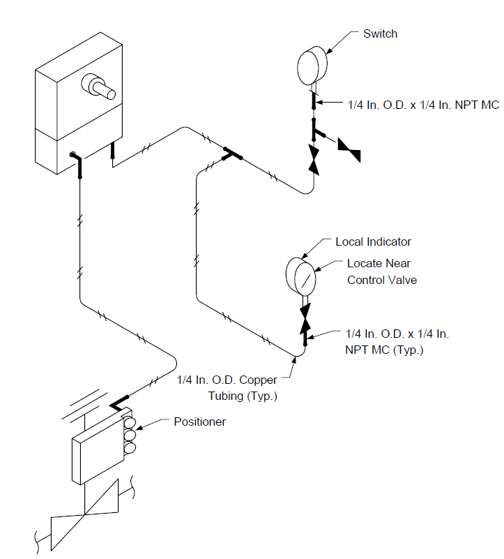
FIGURE 34
PNEUMATIC PIPING LEVEL TRANSMITTER WITH SWITCH AND TRANSDUCER
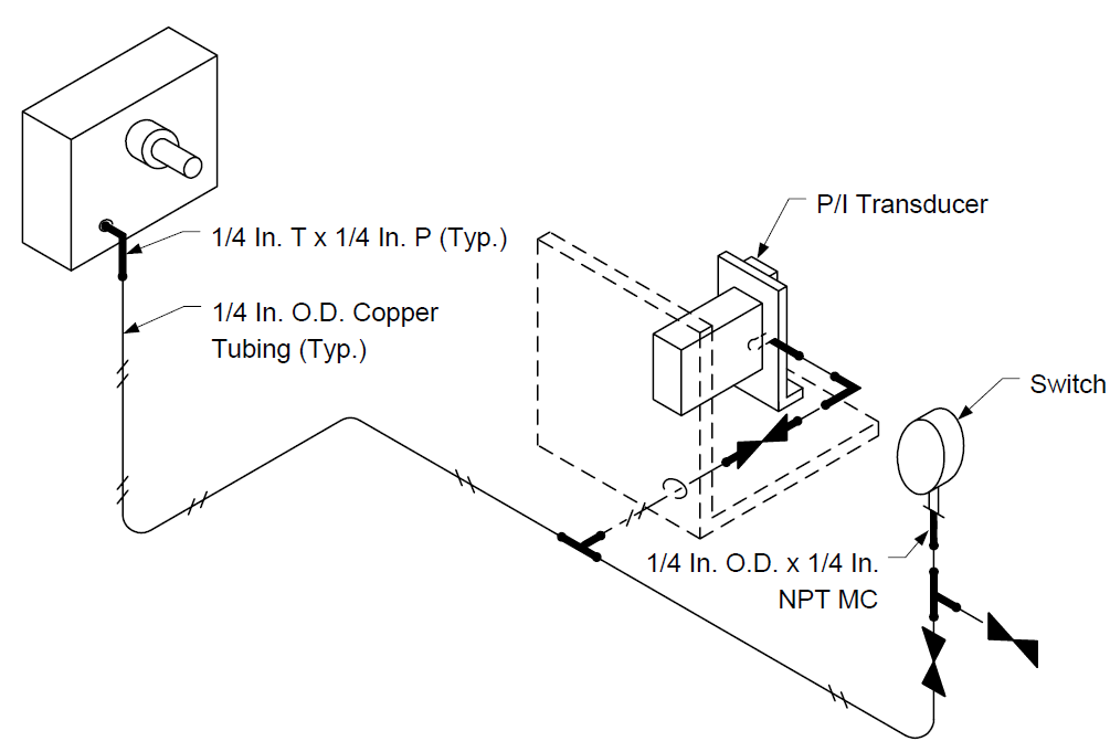
FIGURE 35
INSTRUMENT PIPING CAPACITANCE LEVEL SWITCH
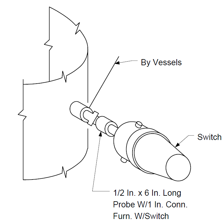
FIGURE 36
INSTRUMENT PIPING DIFF. PRESS. INDICATOR & GAUGE GAS SERVICE
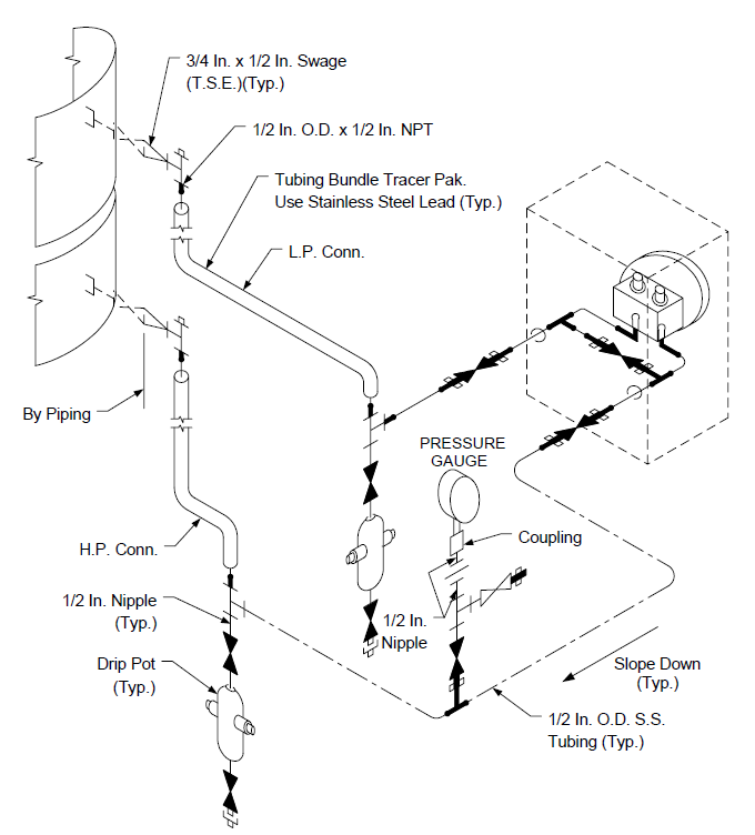
FIGURE 37
PNEUMATIC PIPING 3–WAY VALVE W/ MANUAL RESET TO CONTROL VALVE
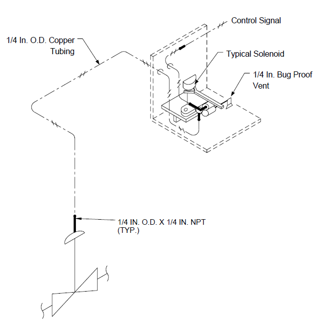
FIGURE 38
INSTRUMENT DRAWING DIAPHRAGM ACTUATOR PIPING
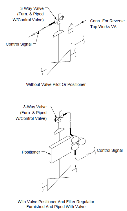
FIGURE 39
INSTRUMENT DRAWING INSTALLATION DETAILS LIQUID LEVEL CONTROLLERS AND GAUGES
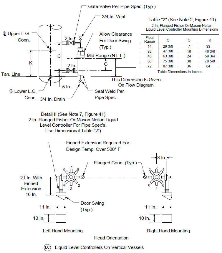
FIGURE 40 INSTRUMENT DRAWING INSTALLATION DETAILS: LIQUID LEVEL CONTROLLERS AND GAUGES
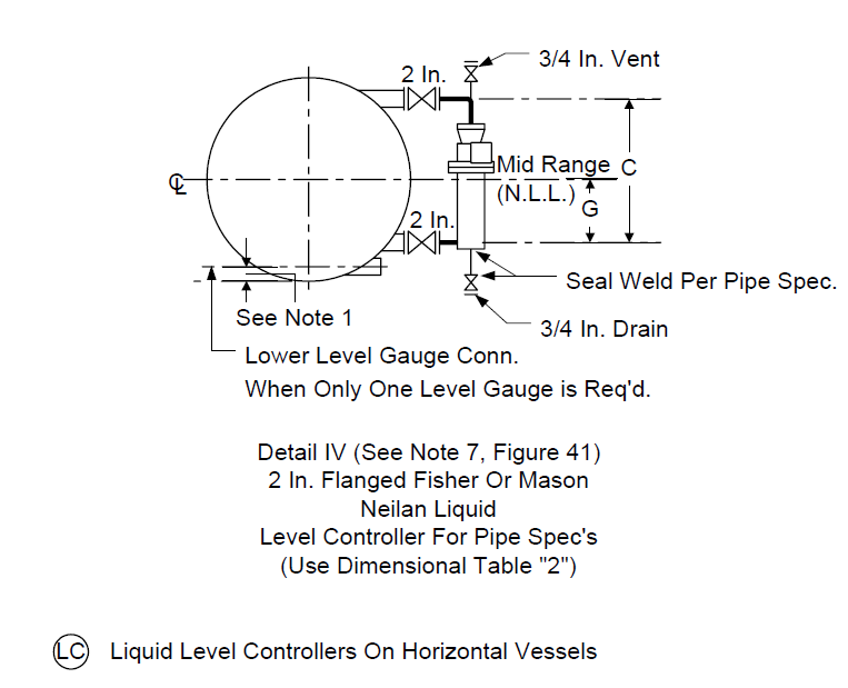
FIGURE 41
INSTRUMENT DRAWING INSTALLATION DETAILS: LIQUID LEVEL CONTROLLERS AND GAUGES
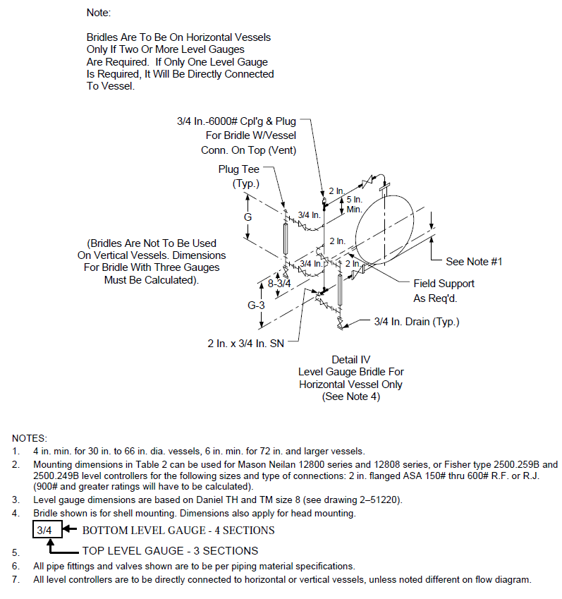
FIGURE 42
INSTRUMENT DRAWING LIQUID LEVEL CONTROLLERS AND LEVEL GAUGES
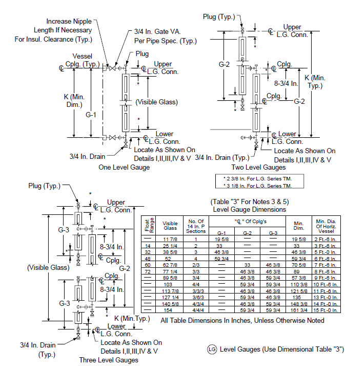
FIGURE 43
INSTRUMENT TAGS ALUMINUM BRACKET TO SUPPORT TAGS FOR CONTROL VALVES
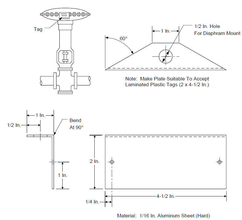
FIGURE 44
INSTRUMENT DRAWING TYPICAL MAIN PANEL LAYOUT
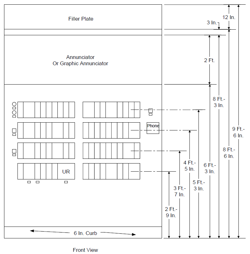
FIGURE 45
INSTRUMENT DRAWING TYPICAL MAIN PANEL LAYOUT


FIGURE 46
INSTRUMENT DRAWING TYPICAL LOCAL PANEL LAYOUT
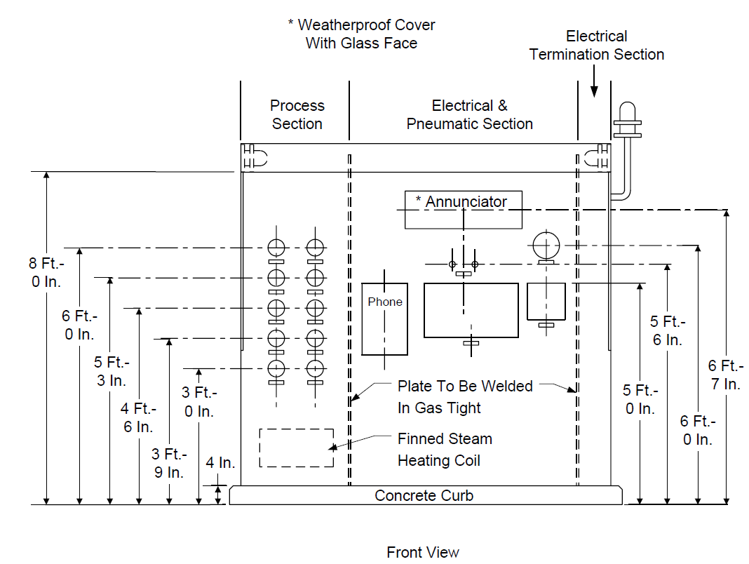
FIGURE 47
INSTRUMENT DRAWING TYPICAL LOCAL PANEL LAYOUT
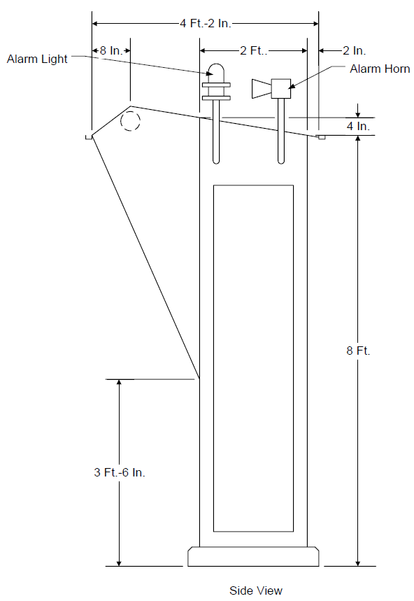
FIGURE 48
TYPICAL INSTRUMENT CONNECTION DETAIL
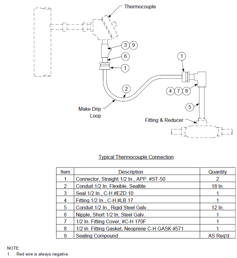
FIGURE 49
INSTRUMENT AIR TYPICAL INSTR. AIR SUPPLY SUBHEADER PIPING
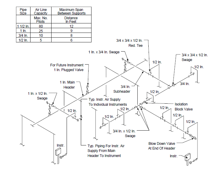
FIGURE 50
INSTRUMENT PIPING DRAFT GAUGE
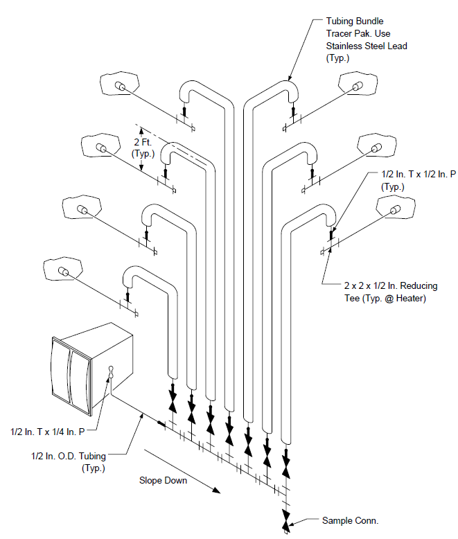
FIGURE 51
PNEUMATIC PIPING AIR SUPPLY PIPING
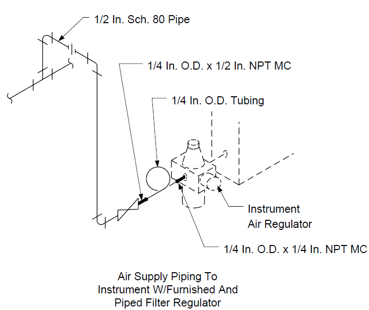
FIGURE 52
PNEUMATIC PIPING PANEL LOADING STATION TO VARIABLE PITCH FAN
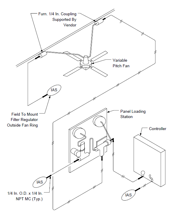
FIGURE 53
PNEUMATIC PIPING I/P CONVERTER SOLENOID VALVE AND TWO CONTROL VALVES
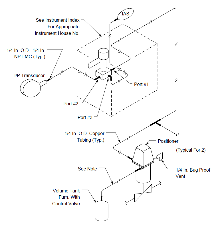
FIGURE 54
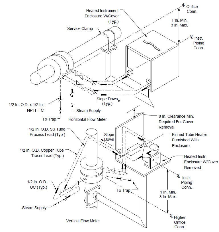
TYPICAL INSTRUMENT WINTERIZATION PROTECTION FOR REMOTE MOUNTED INSTRUMENT
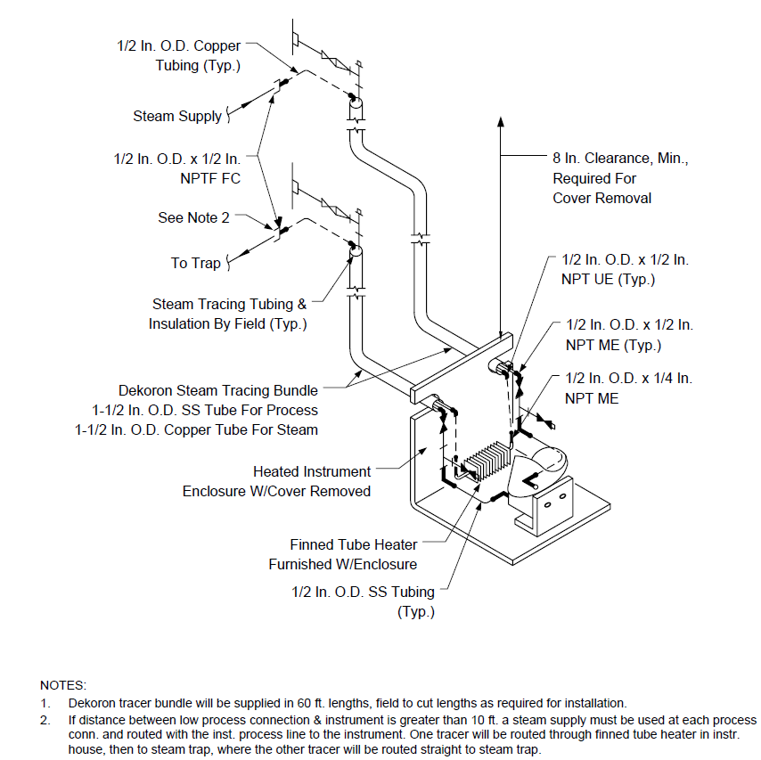
FIGURE 55
TYPICAL INSTRUMENT WINTERIZATION PROTECTION
© 2026 Inflection Point Engineering, LLC. All rights reserved. The content of this page — including calculation methods, reference data, written analysis, interactive tools, and source code — is the intellectual property of Inflection Point Engineering, LLC and is protected under applicable copyright, trademark, and trade secret laws. Unauthorized reproduction, redistribution, modification, or derivative use in whole or in part is prohibited without prior written consent.
Disclaimer. This material is provided for informational and educational purposes only and does not constitute professional engineering advice. Calculations, reference data, and methodologies are based on published standards and accepted engineering practice but are not a substitute for engineering judgment, site-specific analysis, or review by a licensed Professional Engineer. Inflection Point Engineering, LLC makes no warranties, express or implied, regarding the accuracy, completeness, or fitness for a particular purpose of any content presented here, and shall not be liable for any direct, indirect, incidental, or consequential damages arising from its use. Users assume all risk associated with applying this content to real-world design, operations, or decisions.
© 2026 Inflection Point Engineering, LLC. All rights reserved.