 Section 12 — Instruments and Controls
Fire Resistant Instrument Cable
IPE Engineering Practice IPE-EP-12-1-26
Document number: IPE-EP-12-1-26 · Section: 12 — Instruments and Controls
SCOPE
- This Practice details the requirements of Fire Resistant 300 volt single pair and multiple pair thermocouple and instrument cable.
- Any deviation from this Practice must be approved by the procedure described in EP 1–1–3.
- A revision bar indicates all changes made to this Revision.
2.0 REFERENCES
The following codes and standards shall be considered as part of this Practice. All documents shall be the latest editions in force on the date of issuance of this Practice.
STANDARDS AND PUBLICATIONS
| IPE Engineering Practices |
|---|
| EP 1–1–3 Deviations to IPE Engineering Practices EP 12–1–1 Control Systems EP 13–2–1 Electrical Detail Design and Construction Practice |
| UL SUBJECT 13 |
| ANSI |
| MC96.1 Temperature Measurement Thermocouples |
| ASTM |
| D412 Test Methods for Rubber Properties in Tension D2863 Method for Measuring the Minimum Oxygen Concentration to Support Candle Like Combustion of Plastics |
| IEEE |
| 383 IEEE Standard for Type Test of Class IE Electric Cables, Field Splices, and Connections for Nuclear Power Generating Stations |
| ICEA |
| S-66-524 Cross–Linked–Thermosetting–Polyethylene–Insulated Wire and Cable for the Transmission and Distribution of Electrical Energy |
| MIL |
| C-24640 Cable, Electrical, Lightweight for Shipboard Use, General Specification |
DEFINITIONS
- Contractor - Company or business that agrees to furnish materials or perform specified services at a specified price and/or rate to the Owner.
- Inspector - A Inflection Point Engineering, LLC appointed engineer or inspector.
- Manufacturer - The recipient of a direct or indirect purchase order for materials and/or equipment. In this context, a direct order is one issued to a manufacturer by a contractor or the Owner. An indirect order is one issued to a manufacturer by a vendor (recipient of a direct order) for materials, fabricated components, or subassemblies.
- Owner - Inflection Point Engineering, LLC.
- Owner’s Engineer - A Inflection Point Engineering, LLC appointed engineer.
- Purchaser - The party placing a direct purchase order. The purchaser is the Owner’s designated representative.
GENERAL REQUIREMENTS
- Fire resistant instrument cable shall be designed to provide extended service while exposed to fire conditions. Installation and insulation stripping should be done with standard/normal tools. No special bending tools, wire pullers, or stripper tool should be required.
- Documentation shall be provided to assure the Owner’s Engineer that the wire maintains continuity for the specified length of time under the fire/continuity test conditions detailed in section 10.0. Continuity shall be maintained for the following periods:
| Single and multipair instrument cable | 30 minutes |
|---|---|
| Single and multipair thermocouple extension cable | 12 minutes |
- All instrument cable shall be UL/FM listed as 300 volt power limited tray cable as a minimum. Cables shall be FM/UL certified for cable tray installation in a Class 1, Group C,D, Division 2 Area. Cables shall meet the cable tray flame tests of UL Standard 13 and IEEE 383.
- The minimum wire gage for single pair cable shall be 16 AWG. The minimum wire gage for multipair cable shall be 20 AWG. Each wire pair in multipair cables shall be numbered.
- Wire identification and jacket color shall be per ANSI MC96.1 color code for thermocouple extension cables. For instrument cable jacket shall be black with black and white pair colors.
- A rip cord shall be laid longitudinally under the jacket to facilitate jacket removal without damage to the pairs/triads.
- Multiple pair construction shall be individual shielded pair with an overall shield.
- Water tight seals shall be applied to both ends of the cable to protect cable ends and to prevent entrance of moisture during transit and out-of-doors storage.
- Cable shall be placed on non-returnable reels with both ends readily accessible for on-the-reel set up and field testing.
INSTRUMENT CABLE SINGLE PAIR/TRIAD CONSTRUCTION
- The conductor shall be bare soft annealed copper #16 AWG minimum, Class B, 7-strand concentric, per ASTM B-8.
- Each pair or triad shall be twisted together with one seven-strand tinned copper drain wire. Drain wire shall be no less than #22 AWG. The lay shall not exceed 2.5” for pairs or 3.5” for triads.
- An aluminum/polyester tape shall be wrapped around each pair or triad with an overlap to ensure 100% shielding.
INSTRUMENT CABLE MULTI-PAIR CONSTRUCTION
- The conductor shall be bare soft annealed copper #20 AWG minimum, Class B, 7-strand concentric, per ASTM B-8.
- Each pair or triad shall be twisted together with one 7-strand tinned copper drain wire. Drain wire shall be no less than #22 AWG. The lay shall not exceed 2.5” for pairs or 3.5” for triads.
- An aluminum/polyester tape shall be wrapped around each pair or triad with an overlap to ensure 100% shielding.
- A #22 AWG conductor, shall be provided has a communication wire.
- An aluminum/polyester tape shall be applied over the assembled core with an overlap to ensure 100% shielding.
- A 7 strand tinned copper drain wire, the same size as the conductor, shall be applied over the aluminum/polyester shield.
THERMOCOUPLE EXTENSION CABLES SINGLE PAIR CONSTRUCTION
- The conductor shall be solid allow, #16 AWG minimum, per ANSI/MC96.1.
- Each pair shall be twisted together with one seven-strand tinned copper drain wire. Drain wire shall be no less than #22 AWG. The lay shall not exceed 2.5”.
- An aluminum/polyester tape shall be wrapped around each pair with an overlap to ensure 100% shielding.
THERMOCOUPLE EXTENSION CABLE MULTI-PAIR CONSTRUCTION
- The conductor shall be solid allow, #20 AWG minimum, per ANSI/MC96.1.
- Each pair shall be twisted together with one 7-strand tinned copper drain wire. Drain wire shall be no less than #22 AWG. The lay shall not exceed 2.5”.
- An aluminum/polyester tape shall be wrapped around each pair with an overlap to ensure 100% shielding.
- A #22 AWG, bare copper conductor, shall be provided has a communication wire.
- An aluminum/polyester tape shall be applied over the assembled core with an overlap to ensure 100% shielding.
- A 7 strand tinned copper drain wire, the same size as the conductor, shall be applied over the aluminum/polyester shield.
CONSTRUCTION SPECIFICATIONS
- Primary Insulation thermoset silicone alloy, 25 Mils or mica tape and Kapton
- Wire Jacket
polymer alloy, thickness per UL Subject 13 or polymer alloy, thickness per MIL-C-24640
- Insulated Wire Tests
temperature rating 90oC per UL Subject 13
blocking oven temperature 200oC no sticking of conductors
humidity resistance 5 megohms for 1000 ft. minimum IR after humidity exposure wire test 100% impulse voltage at 8kv
OR
100% 3000Hz AC Spark Test
insulation resistance 2500 megohms for 1,000 ft. surface resistance 5 megohms inches
- Cable Jacket
temperature 90o per UL Subject 13
ultimate tensile Strength, psi min 1500 per ASTM D 412 ultimate elongation, % min 125 per ASTM D 412
Air oven aging, 7 days at 121oC retained tensile, % min 60 retained elongation, % min 60
limiting oxygen Index, % min 42 per ASTM D-2863 halogen content, max % 18
oil aging ASTM #2 oil, 18 hrs at 100oC
% retained tensile, min 75
% retained elongation, min 80
- Cable
cold bend -20oC pass per UL Subject 13 minimum installation temperature -10oC bending radius – installation 6 X cable diameter
bending radius - permanent training 4 X cable diameter
FIRE/CONTINUITY TEST
- This test is intended to determine the ability of the cable to maintain continuity under a fire condition.
- Cables arrangement and flame conditions are those detailed by IEEE 383 or those detailed in MIL-C-24643.
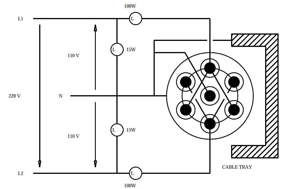
- During the flame conditions of IEEE 383, NURREG 1.31, the time to continuity failure of the cable is monitored by means of a 220 volt, center tapped isolation transformer. (See Figure 1 )
- Power for the time to failure circuit is supplied by means of a 220 volt, center tapped isolation transformer.
- Connect neutral of power to tray, shield and center conductor or multiconductor cable if applicable.
- Connect a 100 watt, 120 volt lamp in series with L1 and the cable and another one in series with L2 and cable.
- Connect each alternate conductor to the one hundred watt lamp that is connected to the power (L1).
- Connect each remaining conductor to the one hundred watt lamp that is connected to the power source (L2).
- Connect a 15 watt, 120 volt lamp from L1 to N, and another one from L2 to N as power circuit monitors.
- The 15 watt lamps will indicate when power is on, the 100 watt lamps will indicate when the insulation fails and conductors have shorted.
11.0 FIGURES
FIGURE 1 TEST FACILITY
© 2026 Inflection Point Engineering, LLC. All rights reserved. The content of this page — including calculation methods, reference data, written analysis, interactive tools, and source code — is the intellectual property of Inflection Point Engineering, LLC and is protected under applicable copyright, trademark, and trade secret laws. Unauthorized reproduction, redistribution, modification, or derivative use in whole or in part is prohibited without prior written consent.
Disclaimer. This material is provided for informational and educational purposes only and does not constitute professional engineering advice. Calculations, reference data, and methodologies are based on published standards and accepted engineering practice but are not a substitute for engineering judgment, site-specific analysis, or review by a licensed Professional Engineer. Inflection Point Engineering, LLC makes no warranties, express or implied, regarding the accuracy, completeness, or fitness for a particular purpose of any content presented here, and shall not be liable for any direct, indirect, incidental, or consequential damages arising from its use. Users assume all risk associated with applying this content to real-world design, operations, or decisions.
© 2026 Inflection Point Engineering, LLC. All rights reserved.