 Section 11 — Refractory, Insulation & Fireproofing
Insulation of Flanged Joints and Valves in Hot Service
IPE Engineering Practice IPE-EP-11-3-6
Document number: IPE-EP-11-3-6 · Section: 11 — Refractory, Insulation & Fireproofing
SCOPE
- This Practice provides procedures and limitations to be applied to the insulating of flanged joints and valves in hot service. The decision to insulate any flanges or valves shall be determined by the Owner, and shall be based on the requirements in EP 11-3-1.
- An asterisk (*) indicates additional information is required. If the job is contracted, this information shall be furnished in the Job Specification.
- Any deviation from this Practice must be approved by the procedure described in EP 1-1-3.
- A revision bar indicates all changes made to this Revision.
2.0 REFERENCES
The latest edition of the following standards and publications are referred to herein.
STANDARDS AND PUBLICATIONS
| IPE Engineering Practices |
|---|
| EP 1-1-3 Deviations to IPE Engineering Practices EP 5-2-2 Flanges, Gaskets and Bolting EP 5-5-4 Bolting Procedures for Flanged Connections EP 10-2-1 Material Requirements for Aggressive Environmental Services EP 11-2-2 Fire Protection Shields for Wafer Valves EP 11-3-1 Insulation Design EP 11-3-2 Insulation Application - Piping EP 11-3-3 Insulation Application - Vessels and Equipment EP 11-3-4 Insulation Application - Storage Tanks and Spheres EP 11-3-5 Removable/Reusable Insulation |
| API Standard |
| Std 605 Large Diameter Carbon Steel Flanges Publ 941 Steels for Hydrogen Service at Elevated Temperatures and Pressures in Petroleum Refineries and Petrochemical Plants |
| ASME Code |
| Sec VIIIPressure Vessels, Division 1 |
| ASME/ANSI Standard |
| B16.5 Piping Flanges and Flanged Fittings |
DEFINITIONS
- Aggressive Environmental Service (AES) - Process services which result in material degradation such as cracking, scaling, blistering, and severe pitting and/or corrosion. Examples of such services are hydrogen service, wet hydrogen sulfide, cyanides, caustic, amine, and hydrofluoric acid. AES process fluid are defined in EP 10-2-1.
- Contractor - Company or business that agrees to furnish materials or perform specified services at a specified price and/or rate to the Owner.
- Design Temperature - Shall be the highest temperature reached during operation, steamout, or regeneration.
- Hydrogen Service - A service defined as a combination of hydrogen partial pressure and temperature above the curve for carbon steel per Figure 1 of API Publication 941, latest edition.
- Hydrogen Rich Service - A service defined as a combination of hydrogen partial pressure and temperature at or below the curve for carbon steel per Figure 1 of API Publication 941, latest edition, and with a hydrogen partial pressure greater than 100 psia.
- Inspector - A Inflection Point Engineering, LLC appointed engineer or inspector.
- Normal Operating Temperature - Shall be the usual operating temperature. This temperature is shown on the piping line schedules or similar project documents.
- Owner - Inflection Point Engineering, LLC.
- Owner's Engineer - A Inflection Point Engineering, LLC appointed engineer.
DESIGN CONDITIONS AND LIMITATIONS OF FLANGES
- (*) Flanged joints are not required to be insulated, unless specified by Owner's Engineer.
- External insulation of hot flanges shall not be used in aggressive environmental services or hydrogen rich service. For permitted services, external flange insulation shall be restricted to applications meeting all the conditions in Table 1.
- Regardless of the limits in paragraph 4.2 above, flanges shall NOT be insulated in the following circumstances:
- Where a mechanical vibration problem is evident or predicted (ex: two phase flow).
- Where there is a recurring or probable leakage problem.
- Where the design temperature of the piping system is equal to or greater than 90 percent of ASME/ANSI B16.5 or ASME B16.47 rating.
- Where the higher temperature caused by insulating the flange exceeds the design temperature used to size flanges under other codes such as ASME Section VIII.
- On orifice flanges and flanges containing figure-8 blanks.
- On heat exchangers, where the flanges contain a tubesheet.
- Where the flanges are internally refractory-lined.
- Where the piping or equipment containing the flanges equal or exceeds 30 inches in diameter, or where the flanges are subject to large bending moments, unless any of these are specifically analyzed for suitability.
- Insulating materials shall be block or blanket, as applicable, and shall conform to the appropriate Practices EP 11-3-2 through 11-3-5.
- Insulating thicknesses shall be determined per the procedure specified in EP 11-3-1.
- When flanges are not insulated, or are insulated with removable insulation, adjacent insulation on piping and vessels shall be terminated to allow removal of bolts without damage to the insulation. The termination shall be weather tight.
- Bare flanges NPS 24 inches and larger operating at temperatures above 600°F shall be protected against the weather to minimize thermal shock problems. Sheet metal weather shields are recommended.
- Emergency Block Valves shall be insulated with calcium silicate per the applicable sections of EP 11-3-2, or with removable insulation per EP 11-3-5.
- Wafer valves shall be insulated with calcium silicate per Figure 1. If wafer valves cannot be insulated, they shall be fire protected per the requirements in EP 11-2-2.
INSULATING PROCEDURES FOR FLANGES AND VALVES
- Typical flange insulation and drain and vent tube details are shown in Figure 1 and Figure 2.
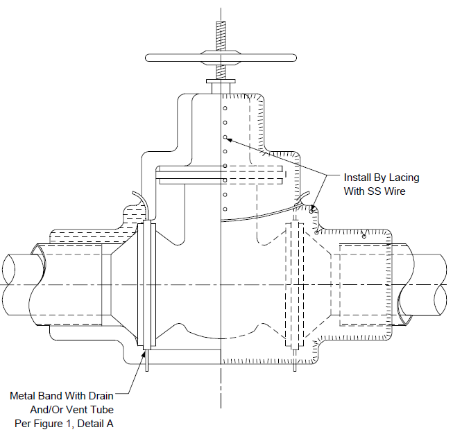
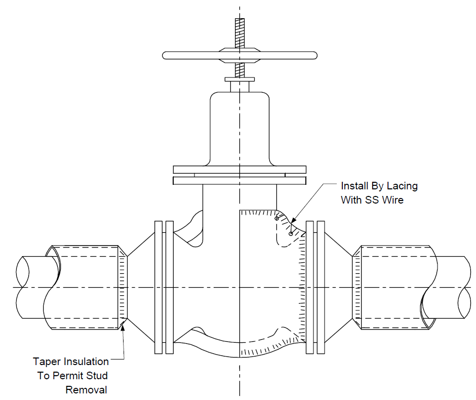
- Typical valve insulation details are shown in Figure 3 and Figure 4.
- Typical manway insulation details are shown in Figure 5 and Figure 6.
- For piping and equipment flanges that qualify for insulation, the procedures listed below shall be followed:
- Pre-tighten bolts, per EP 5-5-4.
- Install metal band containing drain and/or vent tubes around the flanges. Orient tubes to discharge in a safe direction (normally drain down and vent up).
- If fluid temperature will be above 400°F, insulation shall be temporarily installed until the operating temperature has been reached and held for a minimum of three hours. Then the bolts shall be post-tightened.
- Insulate with either permanent or removable insulation as indicated on the drawings.
6.0 TABLES
TABLE 1
FLANGE INSULATION RESTRICTIONS
| SERVICE/MATERIALS | RESTRICTIONS |
|---|---|
| Maximum fluid design temperature Maximum design pressure Flange material Insulation details Bolt material grade |
550°F (1) 600 psig (1) CS, or low alloy (to 5% Cr) (2), (3), (4), (5) B7, B16 |
NOTES:
- Steam service flanges may be insulated for temperatures up to a maximum fluid design temperature of 750°F and a maximum design pressure of 650 psig.
- Insulation systems around flanged joints shall be provided with an NPS 1/2 inch drain tube or vent. For hydrocarbon services, the flange periphery shall, in addition, be fitted with a leak band.
- Stainless metal jacketing is required, unless Removable Insulation is used.
- The design shall permit removal of the insulation system without destruction of the insulation of the connective piping.
- (*) Drains and vents shall be piped to a safe location, as specified, for the following services: highly corrosive, flammable and combustible liquids with operating temperatures above their flash points, light hydrocarbons (lighter than 68° API).
- All insulated flanges shall comply with EP 5-2-2 and shall be bolted per EP 5-5-4.
7.0 FIGURES
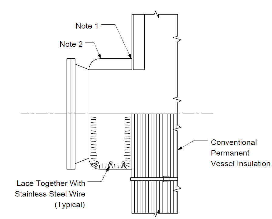
FIGURE 1
TYPICAL PERMANENT INSULATION FOR FLANGED JOINTS
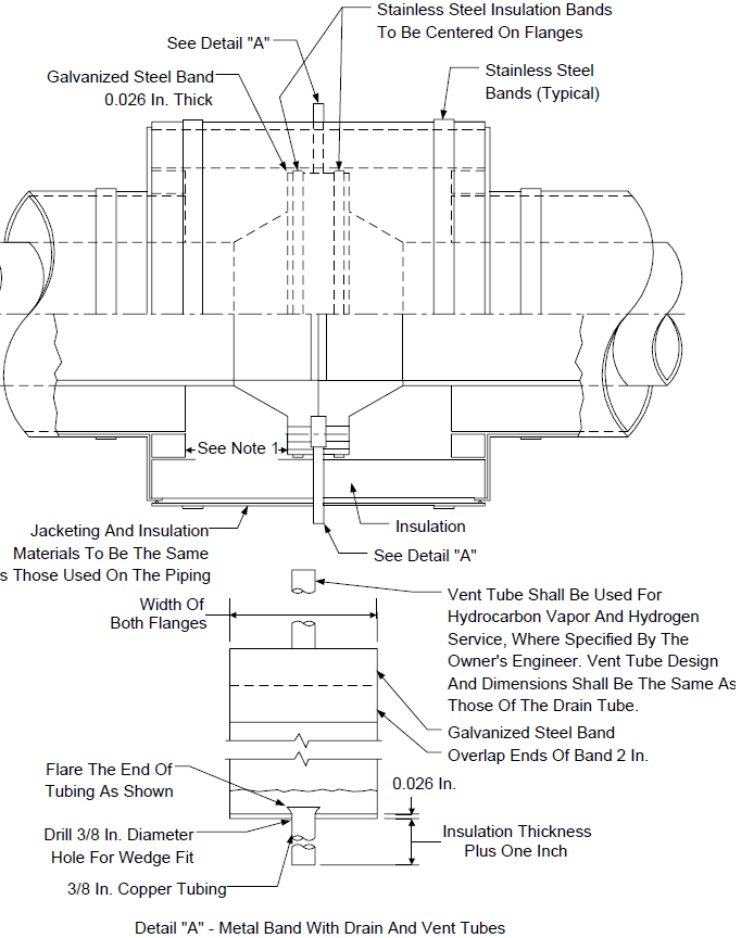
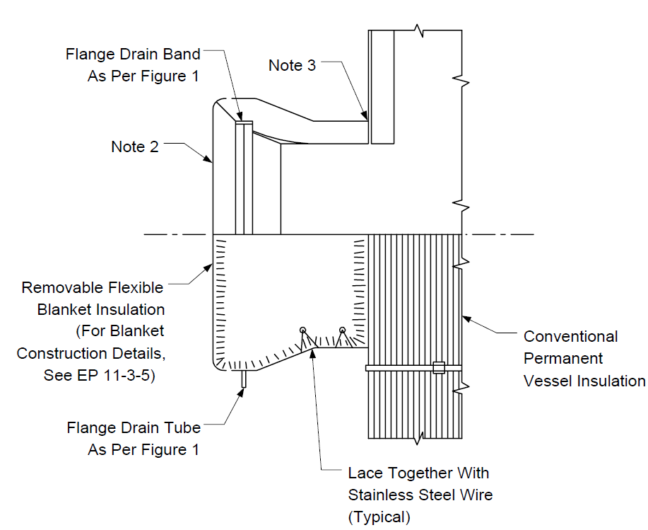
FIGURE 2
REMOVABLE FLEXIBLE INSULATION FOR FLANGES
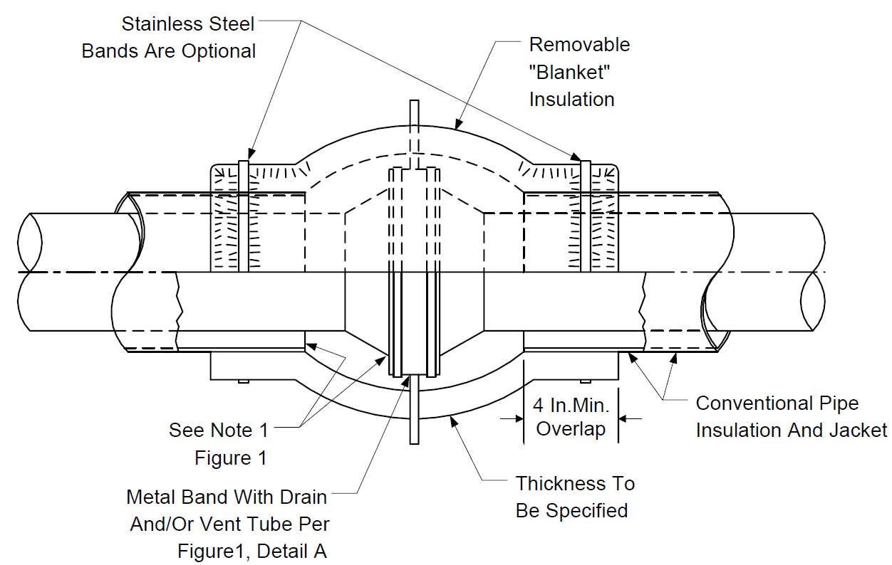
NOTES:
- Install by lacing with ss wire.
- For blanket construction details see EP 11-3-5.
FIGURE 3
FOR SERVICES BELOW 550 °F AND 600 PSIG - TYPICAL VALVE INSULATION - INCLUDING FLANGES
NOTES:
- Identify each piece of insulation on outside surface by method approved by Owner's Engineer.
- For blanket construction details see EP 11-3-5.
FIGURE 4
FOR SERVICES ABOVE 550oF OR 600 PSIG - TYPICAL VALVE INSULATION - EXCLUDING FLANGES
NOTES:
- Identify each piece of insulation on outside surface by method approved by Owner's Engineer.
- For blanket construction details, see EP 11-3-5.
FIGURE 5 TYPICAL MANWAY DETAILFOR SERVICES BELOW 550oF AND 600 PSIG
NOTES:
- See Section 4.0 of this practice for restrictions regarding the use of flange insulation.
- Identify cover on outside surface by method approved by Owner's Engineer.
- Secure manway cover to shell insulation cover by method approved by Owner's Engineer.
FIGURE 6 TYPICAL MANWAY DETAIL FOR SERVICES ABOVE 550°F OR 600 PSIG
NOTES:
- Secure manway cover to shell insulation cover by method approved by Owner's Engineer.
- Block insulation shall be used if removable covers are not installed.
- Insulation shall allow for removal of bolts without damage to the insulation when block insulation is when used.
© 2026 Inflection Point Engineering, LLC. All rights reserved. The content of this page — including calculation methods, reference data, written analysis, interactive tools, and source code — is the intellectual property of Inflection Point Engineering, LLC and is protected under applicable copyright, trademark, and trade secret laws. Unauthorized reproduction, redistribution, modification, or derivative use in whole or in part is prohibited without prior written consent.
Disclaimer. This material is provided for informational and educational purposes only and does not constitute professional engineering advice. Calculations, reference data, and methodologies are based on published standards and accepted engineering practice but are not a substitute for engineering judgment, site-specific analysis, or review by a licensed Professional Engineer. Inflection Point Engineering, LLC makes no warranties, express or implied, regarding the accuracy, completeness, or fitness for a particular purpose of any content presented here, and shall not be liable for any direct, indirect, incidental, or consequential damages arising from its use. Users assume all risk associated with applying this content to real-world design, operations, or decisions.
© 2026 Inflection Point Engineering, LLC. All rights reserved.