 Section 11 — Refractory, Insulation & Fireproofing
Removable-Reusable Insulation
IPE Engineering Practice IPE-EP-11-3-5
Document number: IPE-EP-11-3-5 · Section: 11 — Refractory, Insulation & Fireproofing
SCOPE
- This Practice covers the mandatory requirements for materials and design of removable/reusable insulation operating at a temperature above the atmospheric dew point.
- Any deviation from this Practice must be approved by the procedure described in EP 1-1-3.
- An asterisk (*) indicates that a decision by the Owner is required or that additional information shall be furnished by the purchaser.
- A revision bar indicates all changes made to this Revision.
2.0 REFERENCES
The latest edition of the following standards and publications are referred to herein.
STANDARDS AND PUBLICATIONS
| IPE Engineering Practices |
|---|
| EP 1-1-3 Deviations to IPE Engineering Practices EP 11-3-6 Insulation of Flanged Joints and Valves in Hot Service |
| ASTM Standards |
| A167 Specification for Stainless and Heat-Resisting Chromium-Nickel Steel Plate, Sheet, and Strip |
| B209 Specification for Aluminum and Aluminum-Alloy Sheet and Plate |
| C547 Mineral Fiber Preformed Pipe Insulation |
| C612 Mineral Fiber Block and Board Insulation |
| C795 Wicking Type Thermal Insulation for Use Over Austenitic Stainless Steels |
| C892 High Temperature Fiber Blanket Thermal Insulation |
| C929 Handling, Transporting, Shipping, Storage, Receiving, and Application of Thermal Insulation Materials to be Used Over Austenitic Stainless Steels |
| Military Specifications |
| MIL-I-16441E Insulation Felt, Thermal, Glass Fiber (to 1200 F) |
DEFINITIONS
- Contractor - Company or business that agrees to furnish materials or perform specified services at a specified price and/or rate to the Owner.
- Design Temperature - Shall be the highest temperature reached during operation, steamout, or regeneration.
- Equipment - Each pump, compressor, product accumulator vessel, pressure relief device, valve, sampling connection system, open-ended valve or line, flange or other connector in VOC service, or devices or systems required by this Practice.
- Fire Exposed Area - An area is considered fire exposed if it is horizontally within 30 feet of any fire potential equipment or of the limits of a potential pool or stream of burning liquid, or if it is vertically within 40 feet above any level at which a fire may be initiated. When a fire can be started above grade, the distance below (to grade) is also considered fire exposed.
- Inspector - A Inflection Point Engineering, LLC appointed engineer or inspector.
- Low Melting Point Alloys - Shall include all alloys with a melting point below 1800°F. This includes the aluminum, copper, and magnesium alloys.
- Manufacturer - The recipient of a direct or indirect purchase order for materials and/or equipment. In this context, a direct order is one issued to a Manufacturer by a Contractor or the Owner. An indirect order is one issued to a Manufacturer by a vendor (recipient of a direct order) for materials, fabricated components, or subassemblies.
- Owner - Inflection Point Engineering, LLC.
- Owner's Engineer - A Inflection Point Engineering, LLC appointed engineer.
FABRICATION REQUIREMENTS
- (*) The location and use of removable or reusable insulation shall be specified by the Owner's Engineer and shall be indicated on the applicable drawing and insulation schedules.
- Flexible insulation pieces are to be one piece design when possible. Each piece shall not exceed 69 lbs. for ease of handling and installation.
- Jackets shall be designed and installed to shed water.
- The removable jackets shall overlap the permanent insulation by a minimum of 4 inches.
- All covers are to be secured to the equipment by bands, velcro fasteners or laced wire.
- All jackets over flanged connections shall have drain and vent tubes per EP 11-3-6 or an alternate means for drainage of fluids shall be provided.
- Each cover or cover segment shall be tagged with a 2" X 4" stainless steel identification tag. This tag shall have room for the vessel or equipment PR number and in the case of a valve, the valve type, size and rating.
- Sewn seam, staples and "hog ring" construction methods are acceptable. The thread used shall be able to withstand full process temperature without degradation.
- The insulation within the jacket shall be mechanically fastened in place to prevent shifting or settling of insulation.
- (*) Insulation for pumps, turbines, gage glasses, and other irregularly shaped equipment or instruments, where required by Owner's Engineer, may be of the removable box type. The fabricated box shall have the interior surface lined with resilient fiber insulation. The fiber lining material shall be specified by the Owner's Engineer. See Figure 1.
ACCEPTABLE MATERIALS
- General
- All insulation material shall be asbestos free.
- Insulating material (either in a dry or water-soaked state) that could react corrosively with the insulated surface shall not be used. Insulating materials to be used on austenitic stainless steel shall comply with ASTM C795. Insulation handling, from Manufacturer to installation, shall be per ASTM C929.
- Insulation Materials
- Mineral wool: This material shall have a neutral pH, a nominal density not less than 10 lb/ft3 and be suitable for 1200°F. Insulation shall conform to ASTM C547, Class 3, or ASTM C612, Type 5.
- Alumina silica ceramic fiber: This material shall conform to ASTM C892 with a density of 8 lb/ft3, and shall be limited to a maximum service temperature of 2300ºF.
- Fibrous glass felt shall be type "E", not less than 9 lb/ft3, and shall comply with military specification number MIL-I-16411E, Type II.
- Flexible removable insulation blankets shall be fiberglass, limited to a maximum service temperature of 800°F. For applications above 800°F, alumina silica ceramic fiber blanket shall be used.
- For temperatures less than 200°F, a non-hygroscopic insulation that is resistant to moisture and chemicals shall be used.
- Insulation Coverings
- Metal lagging shall comply with the following specifications, with thickness not less that indicated:
- Stainless steel: ASTM A167, types 302, 304, or 316. Minimum thickness of 0.010 inches.
- Aluminum: ASTM B209, type 3003 or 5005. Minimum thickness of 0.016 inches.
- (*) All metal lagging shall have a vapor barrier of colored polyethylene-surlyn, colored converted epoxy, or 50-pound polyethylene-kraft paper thermally bonded to the inside surface. Flat stucco embossed jacketing, or prefabricated lagging sections, shall be used. Where specified by Owner's Engineer, the outside of the lagging shall be coated with a color converted epoxy.
- Stainless steel jacketing shall be used for removable "boxes" when:
- Insulating low melting point alloys.
- The insulation is in a fire exposed area, or considered as fireproofing.
- For flexible removable insulation, the outside covering (cold side) shall be 16 oz./yd2 silicone coated fiberglass equal to Alpha Maritex #3259-2-SS or teflon coated material equal to Chemfab Q Guard 14 D. See Figure 2A.
- The inside covering for flexible insulation shall be as follows (See Figure 2B):
- For services up to 450°F, the inner cover is the same as listed in paragraph 5.3.4 above.
- For services above 450°F an inner wrapping of stainless foil, 0.002 inch minimum, shall be used.
- Flexible removable insulation shall be encased in stainless steel tubular knitted mesh, 0.011 inch thick wire, type 304 up to 800°F; type 321 from 801 to 1200°F; and Inconel from 1201°F to 1600°F
- Equipment where the system is considered as fireproofing and/or insulation systems in low melting alloys (such as aluminum), shall be capable of withstanding the force of firehose stream impingement.
- Metal jackets, removable boxes, are required when insulating for noise control or combined thermal and noise control.
- Accessories
- All hog rings, staples, tie wires, etc. shall be annealed stainless steel, type 304.
- Tie wire shall be 14 BWG.
- Bands used to secure insulation shall be 3/4 inch wide by 0.020 inch minimum thickness.
6.0 FIGURES
FIGURE 1 REMOVABLE INSULATION BOX
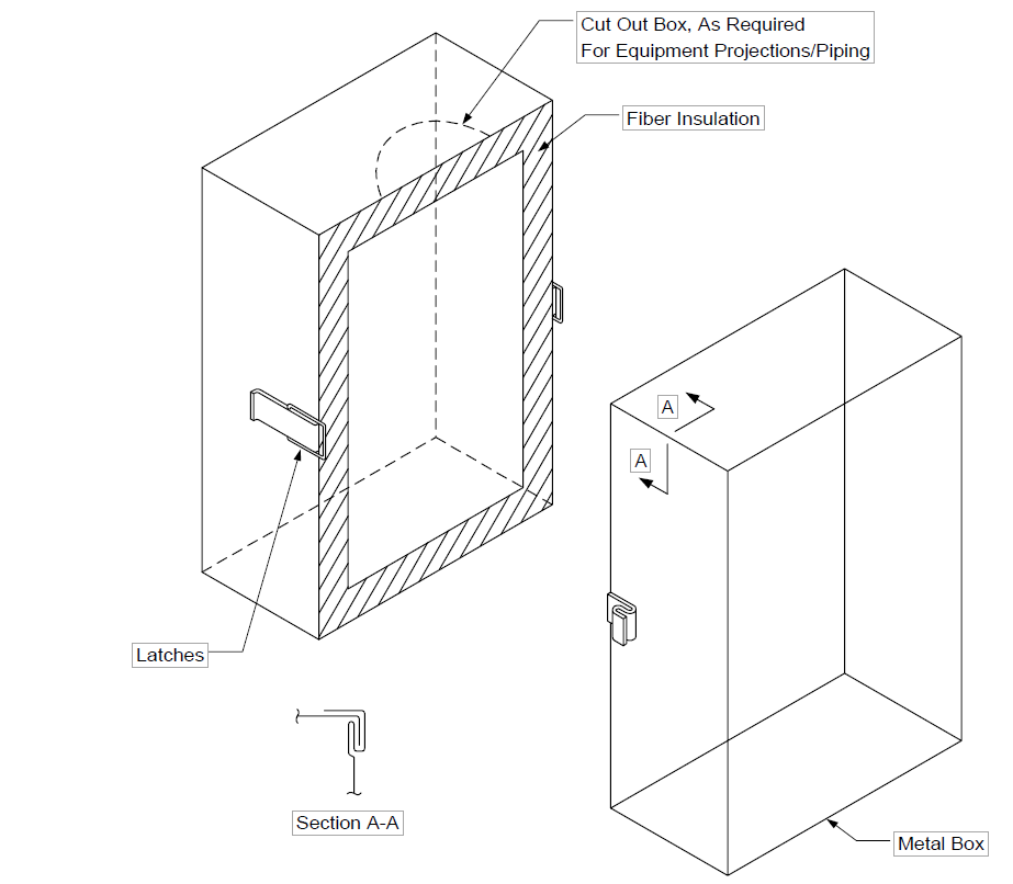
NOTE: All joints/seams to be locking type.
FIGURE 2A
REMOVABLE FLEXIBLE INSULATION, COMPOSITION OF TYPICAL BLANKETS FOR SERVICES BELOW 450 F
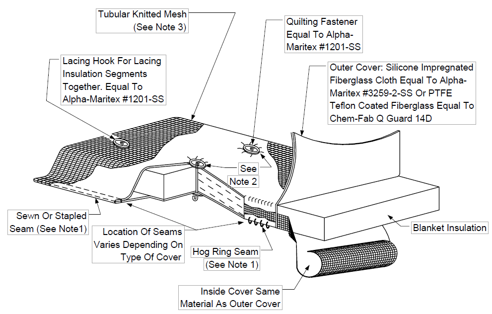
NOTE:
- Method of joining at seams shall be one of the following:
- Sewing (preferred method) using double-sewn lap-seam stitching, with a minimum of 10 to 14 stitches per inch. Thread shall be equal to ALPHA D-18, Teflon coated fiberglass or Standard 69 Bonded Nomex.
- Stainless staples may be used in lieu of stitching. Staples shall be spaced on no greater than 1 in. centers.
- Hog-rings, 16-gauge stainless steel on 1 in. centers. The parts being joined shall overlap by 3/4 in. minimum.
- In lieu of lacing hooks; lacing straps with stainless steel D-ring buckles, and Velcro fasteners may be used with approval of Owner's Engineer.
- Tubular knitted wire mesh of 0.011 thick wire, Type 304 stainless steel up to 800F.
FIGURE 2B
REMOVABLE FLEXIBLE INSULATION, COMPOSITION OF TYPICAL BLANKETS FOR SERVICES FROM 450 F TO 1600 F
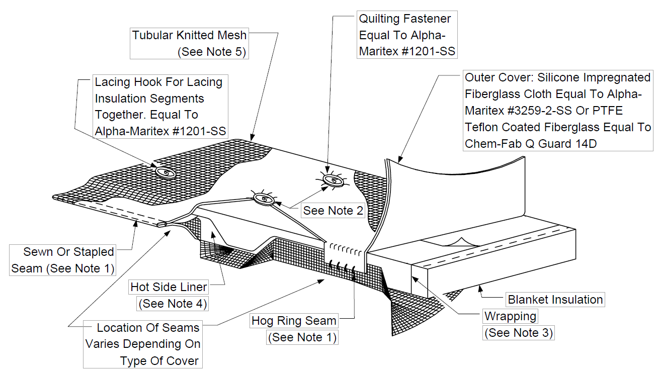
NOTE:
- Method of joining at seams shall be one of the following:
- Sewing (preferred method) using double-sewn lap-seam stitching, with a minimum of 10 to 14 stitches per inch. Thread shall be equal to ALPHA D-18, Teflon coated fiberglass or Standard 69 Bonded Nomex.
- Stainless staples may be used in lieu of stitching. Staples shall be spaced on no greater than 1 in. centers.
- Hog-rings, 16-gauge stainless steel on 1 in. centers. The parts being joined shall overlap by 3/4 in. minimum.
- In lieu of lacing hooks; lacing straps with stainless steel D-ring buckles, and Velcro fasteners may be used with approval of Owner's Engineer.
- Insulation is to be single-wrapped in stainless steel foil - minimum 0.002 in. thick, prior to insertion in envelope of wire mesh, cloth, and wire mesh as approved by Owner's Engineer.
- On items 4 in. NPS and smaller, the foil wrapping may be incorporated in the jacketing system as the hot side liner inside the wire mesh, when approved by Owner's Engineer.
- Tubular knitted wire mesh of 0.011 in. thick wire, Type 304 stainless steel up to 800 F; Type 321 from 801 to 1200 F and Inconel from 1201 F to 1600 F to totally encapsulate the insulation system when specified.
© 2026 Inflection Point Engineering, LLC. All rights reserved. The content of this page — including calculation methods, reference data, written analysis, interactive tools, and source code — is the intellectual property of Inflection Point Engineering, LLC and is protected under applicable copyright, trademark, and trade secret laws. Unauthorized reproduction, redistribution, modification, or derivative use in whole or in part is prohibited without prior written consent.
Disclaimer. This material is provided for informational and educational purposes only and does not constitute professional engineering advice. Calculations, reference data, and methodologies are based on published standards and accepted engineering practice but are not a substitute for engineering judgment, site-specific analysis, or review by a licensed Professional Engineer. Inflection Point Engineering, LLC makes no warranties, express or implied, regarding the accuracy, completeness, or fitness for a particular purpose of any content presented here, and shall not be liable for any direct, indirect, incidental, or consequential damages arising from its use. Users assume all risk associated with applying this content to real-world design, operations, or decisions.
© 2026 Inflection Point Engineering, LLC. All rights reserved.