 Section 11 — Refractory, Insulation & Fireproofing
Insulation Application - Tanks and Spheres
IPE Engineering Practice IPE-EP-11-3-4
Document number: IPE-EP-11-3-4 · Section: 11 — Refractory, Insulation & Fireproofing
FIGURE 7 "BELT LOOP" DETAIL 28
FIGURE 8 TANK PENETRATION INSULATION DETAILS 29
FIGURE 9 TERMINATION OF POLYURETHANE FOAM 30
FIGURE 10 EXPANSION JOINT AND BONDING DETAILS 31
FIGURE 11 STIFFENER RING INSULATION 32
FIGURE 12 SHEATHING AT STIFFENERS 33
FIGURE 13 FLASHING AT NOZZLES AND OTHER PROJECTIONS 34
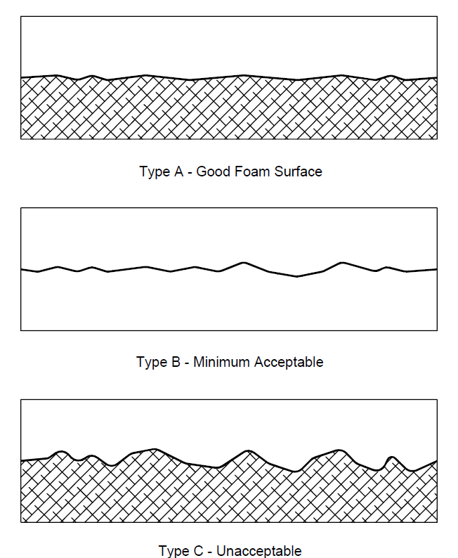
FIGURE 14 FOAM SURFACES COMPARED 35
1.0
1.1
1.2
1.3
1.4
1.5
2.0
SCOPE
This Practice covers the mandatory requirements for the materials and application of external insulation to outdoor storage tanks and spheres designed in compliance to EP 9-1-1, EP 9-2- 1 and EP 9-4-1.
Any deviation from this Practice must be approved by the procedure described in EP 1-1-3.
This Practice is appropriate for attachment to an inquiry or purchase document when accompanied by the referenced IPE Engineering Practices and the completed data sheets included in EP 11-3-4 DS, as required.
An asterisk (*) indicates that a decision by the Owner is required, or that additional information shall be furnished by the purchaser.
A revision bar indicates all changes made to this Revision.
REFERENCES
The latest edition of the following standards and publications are referred to herein.
STANDARDS AND PUBLICATIONS
| IPE Engineering Practices |
|---|
| EP 1-1-3 Deviations to IPE Engineering Practices EP 9-1-1 Atmospheric Storage Tanks EP 9-1-2 Welding Requirements for Atmospheric Storage Tanks EP 9-2-1 Low Pressure Storage Tanks EP 9-4-1 Pressure Storage Spheres EP 10-3-1 Shop Painting EP 11-3-4 DS Insulation Application - Tanks and Spheres Data Sheet EP 11-3-6 Insulation of Flanged Joints and Valves in Hot Service |
| API |
| Std 650 Welded Steel Tanks for Oil Storage |
| ASTM |
| A167 Specification for Stainless and Heat-Resisting Chromium-Nickel Steel Plate, Sheet and Strip B209 Specification for Aluminum and Aluminum-Alloy Sheet and Plate C449 Mineral Fiber Hydraulic-Setting Thermal Insulating and Finishing Cement C533 Calcium Silicate Block and Pipe Thermal Insulation C55 Cellular Glass Block and Pipe Thermal Insulation C591 Unfaced Preformed Rigid Cellular Polyurethane Thermal Insulation C592 Mineral Fiber Blanket Insulation C612 Mineral Fiber Block and Board Insulation |
STANDARDS AND PUBLICATIONS (CONTINUED)
| ASTM (Continued) |
|---|
| C795 Wicking Type Thermal Insulation for Use Over Austenitic Stainless Steels C892 High Temperature Fiber Blanket Thermal Insulation C929 Handling, Transporting, Shipping, Storage, Receiving, and Application of Thermal Insulation Materials to be Used Over Austenitic Stainless Steel D756 Determination of Weight and Shape Changes of Plastics Under Accelerated Service Conditions D1621 Test Method for Compressive Properties of Rigid Cellular Plastics D1622 Apparent Density of Rigid Cellular Plastics D2126 Response of Rigid Cellular Plastics to Thermal and Humid Aging D2856 Open Cell Content of Rigid Cellular Plastics by the Air Pycnometer. E84 Surface Burning Characteristics of Building Materials |
| SSPC |
| SP 6 Commercial Blastcleaning |
DEFINITIONS
- Contractor - Company or business that agrees to furnish materials or perform specified services at a specified price and/or rate to the Owner.
- Design Temperature - Shall be the highest temperature reached during operation, steamout, or regeneration.
- Fire Exposed Area - An area is considered fire exposed if it is horizontally within 30 fiit of any fire potential equipment or of the limits of a potential pool or stream of burning liquid, or if it is vertically within 40 feet above any level at which a fire may be initiated. When a fire can be started above grade, the distance below (to grade) is also considered fire exposed.
- Inspector - A Inflection Point Engineering, LLC appointed engineer or inspector.
- Low Melting Point Alloys - Shall include all alloys with a melting point below 1800 F. This includes the aluminum, copper, and magnesium alloys.
- Manufacturer - The recipient of a direct or indirect purchase order for materials and/or equipment. In this context, a direct order is one issued to a manufacturer by a contractor or the Owner. An indirect order is one issued to a manufacturer by a vendor (recipient of a direct order) for materials, fabricated components, or subassemblies.
- Owner - Inflection Point Engineering, LLC.
- Owner's Engineer - A Inflection Point Engineering, LLC. appointed engineer.
- Purchaser - The party placing a direct purchase order. The purchaser is the Owner's designated representative.
- PSM - Process Safety Management.
DRAWING AND INSULATION SCHEDULES
(*)Drawing and insulation schedules shall be supplied to the contractor by the Owner's Engineer and shall contain the following information:
- Equipment (designated by equipment number) to be insulated and extent of insulation if only partial coverage is required.
- Equipment that requires special insulation to prevent stress corrosion cracking of austenitic stainless steel.
- Type, total thickness, and number of layers of insulation required.
- Design temperatures.
- Extent of insulation designated as fireproofing.
- Equipment that requires insulation only for personnel protection.
- Equipment to be heat traced or refrigerated.
- Type of insulation weatherproof covering.
- Designated areas and requirements for surface preparation and painting.
- Areas specified to be insulated for noise control or combined thermal and noise control.
- Manways and flanges to be insulated.
- Areas where insulation is to be both removable and reusable.
- Type and location of expansion joints.
- Surfaces specified to be insulated for winterizing.
- Areas to be insulated for foot traffic.
DOCUMENTATION
- (*)Proposal Information
The following data, as applicable, shall be submitted to purchaser for approval by the Owner's Engineer.
- Product specifications.
- Material storage requirements, including shelf life and temperature.
- Design and application details of expansion joints.
- Repair procedures for damaged areas.
- Inspection and testing procedures.
- Recommended safety precautions, such as the proposed method of electrical grounding of equipment (i.e., blast cleaning and spray application).
- Contractor Specification
The Owner's Engineer shall supply a supplemental job specification to the insulation contractor. The job specification shall include all applicable drawing and insulation schedules, material specifications, and all obligations and responsibilities required for the job.
- Qualifications of Foam Applicators
- Foam shall be installed only by foam applicators who are experienced in the proposed application methods and who use equipment with positive metering.
- The foam spray mechanics shall have a minimum of two years' field spraying experience.
- Bidders shall submit a listing of similar installations completed by them, including type of foam and weather protection, date of completion, location, and contacts. If the proposed foam or protective coating has not been used by a bidder, he shall submit a listing of successful installations by others and a confirmation that the manufacturer(s) will furnish field assistance.
- Bidders shall submit resumes of recent experience of those supervisory personnel and spray mechanics that will be used on the job.
- Contractor's Responsibility
- The contractor shall furnish all supervision, labor, tools, equipment, supplies, scaffolding and transportation necessary to execute this Practice. All materials will be supplied by the Contractor except those specifically noted otherwise.
- The insulation/primer/weatherproofing manufacturers shall accept responsibility for their products in writing.
- The contractor shall secure in writing from insulation/primer/weatherproofing manufacturers their acceptance of responsibility for their products.
- The application contractors shall accept responsibility for their work in writing for a period of one year.
- Before field work starts, the contractor and material suppliers will be required to attend a meeting to discuss:
- Work Inspection
- Application Procedure and Applicator Tests
- Location
- Work Schedule
- Safety Rules and Regulations.
- On the days of application, the contractor shall complete submitted to the Owner daily the "Quality Control Daily Reports" (see data sheets in EP 11-3-4 DS).
ACCEPTABLE MATERIALS
- General
- API 650 and 620 tanks shall be insulated with one or more of the following:
- Cellular glass (max. service temperature 450F)
- Fiberglass (max. service temperature 850F)
- Mineral wool (max. service temperature 450F)
- Polyurethane foam (max. service temperature 175F)
- Calcium Silicate (max. service temp. 1200F)
- Perlite (maximum service temp. 1200F)
- Cellular glass and polyurethane foam are the preferred insulation materials for refrigerated tanks and spheres.
- Refrigerated tanks and spheres operating at temperatures less than -60F shall have the insulation reviewed and approved by the Owner's Engineer.
- Insulation systems using polyurethane foam on LPG storage spheres (API 2510) shall be reviewed and approved by Owner's Engineer and a PSM representative.
6.2
6.2.1
6.2.2
6.2.3
6.2.4
6.2.5
6.2.6
6.2.7
6.2.8
Insulated tanks which require fireproofing shall have calcium silicate as the outside layer of insulation. Alternate designs using a combination of passive fireproofing materials and insulation must be approved by the Owner's Engineer and a PSM representative.
Insulation for noise control shall be limited to fiberglass (6-8 lb./ft.3) or mineral wool (8-10 Ib./ ft.3). The requirements in Section 7.10 shall also apply.
Rigid and Resilient Insulation
Calcium silicate block insulation shall be suitable for 1200F and comply with ASTM C533, Type 1 requirements. For fire exposed areas, calcium silicate shall be manufactured to withstand at least 1800F and shall comply with ASTM C533, Type 2.
Mineral wool shall have a neutral pH, a nominal density not less than 8 lb/cu. ft. and be suitable for 1200F, except as noted. Additional requirements are:
- Blankets shall conform to ASTM C592, Class II. They shall be faced with wire mesh on both sides. Mesh shall not be galvanized for use on austenitic steel surfaces.
- Blocks and boards shall conform to ASTM 0612, Type 5. The minimum nominal density shall be 10 lb/cu. ft.
- All mineral wool shall be silicone treated for water resistance.
Cellular glass shall conform to ASTM C552 and is limited to a maximum service temperature of 450F.
Alumina silica ceramic fiber blanket shall conform to ASTM C892 with a density of 8 lb/cu. ft. and a maximum use temperature of 2300F.
Insulating cement shall be mineral fiber ASTM C449. Cement shall set to a hard smooth monolithic finish.
Polyurethane foam shall comply with ASTM C591, Type II, with a flame spread rating not exceeding 25 per ASTM E84. For roof applications, and areas of high traffic, foam must have a minimum compressive strength (parallel to rise) of 40 psi. Polyurethane foam is limited to a maximum service temperature of 175F.
- Cellular urethane foam insulation shall have a minimum nominal density of 2 lb/ft3 per ASTM D1622.
- Cell structure shall be uniform throughout the core. Elongated cells shall be no longer than 3 times the smallest dimension. Test per ASTM D2856, procedure A.
- Dimensional stability shall be tested per ASTM D2126. The volumetric change shall not exceed 2% after 7 days' exposure at -20F (cold aging); and after 7 days' exposure at 200F (hot aging).
- Humid aging shall be determined per ASTM D756, procedure A, with a maximum 3% change in linear dimensions.
Fiberglass shall be limited to a maximum service temperature of 850F. Block and board insulation shall have a minimum density of 6 lb/ft3 and comply with ASTM C612, type III.
Perlite shall comply with ASTM C610, Type II material, and shall have a sodium silicate binder. The material shall also be subjected to a high temperature test (1200F), and be checked for smoking, charring, cracking, and other signs of physical deterioration.
6.3
6.3.1
6.3.2
6.3.3
6.3.4
6.3.5
6.3.6
6.3.7
6.3.8
equal.
6.4
6.4.1
Insulation Coverings
Weatherproofing jacket for non-fire exposed areas, except for those items which comply with Section 6.3.2 , shall be aluminum according to the following:
- Sheets and rolls shall be 1-1/4 inch corrugated 0.020 inch thick.
- Flat stucco embossed aluminum, 0.020 inch thick, shall be used on heads, transitions, stiffener rings, and flashing.
- Aluminum alloy to be ASTM B209, Type 3003 or 5005.
- At the discretion of the Owner's Engineer, jacketing in non-fire exposed areas may be upgraded to stainless steel.
Weatherproof covering for fire exposed areas, equipment of low melting alloys, or polyurethane foam within a process unit, shall be 0.01 inch thick stainless steel ASTM A167, Type 316.
Covering steel shall be according to the following:
- Sheets and rolls shall be 0.01 inch thick with 1-1/4 inch corrugations in the long direction.
- Formed heads, transitions, stiffener rings, and flashing shall be 0.010 inch thick, smooth, interlocking gore type.
Fireproofing mastic shall be a breather type, asbestos free, with a flame spread of 4 or less (Vimasco WC-1 or equal).
All jacketing materials shall have a vapor barrier of colored converted epoxy, colored polyethylene, or 50-pound polyethylene-kraft paper moisture barrier 100 percent bonded to the inside surface. When specified on the insulation schedules, the outside of the jacketing shall be coated with a color converted epoxy.
Insulation systems on low melting alloys (such as aluminum), or on equipment where the system is considered as fireproofing, shall be capable of withstanding the force of firehose stream impingement.
Elastomeric coatings shall be used over cellular glass insulation when metal jackets are not provided.
Applied coatings of mastic or elastomeric materials shall comply with the following:
- A flame spread classification of not more than 25 per ASTM E84.
- A demonstrated resistance to solar radiation.
- Flexible at the lowest temperature to which they are exposed.
- Compatible with the insulation materials.
- Mastics shall be of the breathing emulsion type.
Mastic Weathercoat shall be a vinyl acrylic Childers Vicryl IPE -10/IPE- 11-1 or
Accessories
Bands shall be stainless steel, Type 316, annealed temper. Sizes shall be 3/4 inch wide by
0.020-inch minimum thickness, with wing type seals. Breather springs shall be used where required for expansion. Bands shall be held in place with screwed keepers.
- Bands shall be marked (color coded blue or stamped as specified by the plant) to indicate
nonasbestos containing insulation. Bands on asbestos containing insulation shall be color coded yellow.
- Seals shall be stainless steel to match bands (regular-wing type, long shank).
- Wire shall be 14 BWG stainless steel, Type 316 annealed temper.
- Reinforcing for applied coatings shall be as follows:
- Wire mesh shall be 1 inch hexagonal woven wire poultry mesh, 0.035 inch (20 BWG) minimum wire diameter. Wire shall be either stainless steel or Monel. The mesh shall be laced into place with wire at least 0.08 inch diameter of the same material.
- Glass Fabric shall be per the coating manufacturer's recommendation for reinforcing fabric in mastic finishes. If not specified, use 10 x 10 open mesh, Childers Chil-Glas #10 or equal.
- Sheet metal screws for securing metal to metal shall be number 8 by 1/2-inch long self tapping, type 316 stainless steel, with neoprene gaskets.
- Breather springs shall be stainless steel to match bands, 5-inch minimum expansion, and a 110 pound load limit (min.). Double springs (lNSUL-MATES-7 RPR Products, Inc., or equal) shall be used for jacketing.
- Sealer/flashing mastic shall be nonshrinking permanently flexible, less than one perm water vapor per 1/16-inch thickness.
- S-Clips for jacketing on vertical tanks shall be stainless steel, Type 316 stainless steel annealed temper, see Figure 1.
- Welded studs for insulation jacket supports shall be stainless steel, Type 316 (see Figure 2).
- Insulation rectangular welding pins (per Figure 2). See paragraph 8.4 for material requirements.
SPECIAL REQUIREMENTS
- Insulation in high traffic areas shall have a minimum compressive strength of 40 psi. When this is not possible, roof walkways shall be installed, per Section 9.1.5.
- (*)Insulation "systems" involving prefabricated panel systems will be evaluated individually. Submit proposals to the Owner's Engineer for review and approval.
INSULATION SUPPORTS
- Insulation supports for cylindrical tanks shall be per Figure 3 - Figure 5 and Section 9.5.5. Support clips for spheres shall be per Figure 6.
- Support rings for use on vertical surfaces shall be spaced no more than 12 feet apart.
- The insulation angle, welded to the top angle, and the insulation support plate at the bottom of the tank shall be furnished in accordance with Figure 3.
- Vessel attachments required for support of insulation and fireproofing shall be as follows:
- Support clips welded to the vessel shall be fabricated from the same material as the vessel.
- Insulation support ring material shall be:
- Carbon steel for carbon steel and low alloy tanks.
- The same as the tank material for all other cases.
- Heat treated items requiring welding pins, clips or studs shall have pins installed prior to heat treatment.
- An angle support ring shall be welded around the base of the tank per Figure 5. This is required for block, blanket, or board insulation.
APPLICATION
- General
- Pressure tests on tanks or spheres shall be completed before insulation is installed.
- Care shall be taken to avoid contact between dissimilar materials which might cause galvanic corrosion (i.e., aluminum in contact with steel, etc.).
- Insulation shall be kept dry and protected against the elements during storage and all stages of application until the weatherproofing has been installed.
- All hot work, welding and burning must be completed prior to insulation application.
- When a tank roof is to be insulated, the following shall apply:
- Roof walkways, which provide access to all roof openings and fittings, shall be installed in those cases where the insulation is unsuitable for walking on per Section 7.1.
- The roof slope shall be at least 1-1/2 inches in 12 inches.
- Gauge hatches, when required, shall be bolted to a roof nozzle.
- When overflows are installed, the overflow detail shall be designed to prevent the overflowing liquid from soaking the tank insulation. Relocating the insulation angle and/or providing adequate splash plates on the overflow connections are two of the methods which may be employed to satisfy this requirement.
- Surface Preparation
- Surface preparation, including any washing of stainless steel surfaces, and primer painting will be the responsibility of the applicator and shall comply with EP 10-3-1. All tanks and shall be primed prior to insulating.
- Surfaces to be insulated shall be dry, and shall have foreign matter removed by solvent cleaning (as necessary, after surface has been primed).
- Blast clean all surfaces and welds before priming to SSPC-SP6 (min.). Follow manufacturer's recommendations for additional requirements, as applicable.
- Before blasting, grind smooth sharp edges, welds, steel slivers, etc., and remove all oil and weld spatter and flux.
- All paints shall be applied to a surface free from oil, moisture, dust, grit, or any other contaminants and discoloration.
- All surfaces shall be primed during the same day they are blasted.
- Projections
- All projections from surfaces shall be insulated completely or to the maximum practical extent (For example, stairway clips shall be insulated to the attachment point of the stair-tread; nozzles shall be insulated to the connective flange), but no less than 2 inches from the tank insulation surface.
- The circumferential stairway shall be made with a stringer on the tank side of the stairs. The stringer shall be supported from the tank shell. Clearance from the insulation shall comply with Section 9.4.1.
9.4
9.4.1
9.4.2
9.4.3
9.4.4
9.4.5
9.4.6
9.5
9.5.1
9.5.2
9.5.3
9.5.4
9.5.5
9.5.6
9.5.7
9.5.8
For polyurethane foam applications wrap steam lines, or other items operating above the foam temperature limit with 1 inch thick fiberglass blanket prior to the foam application.
Access and Clearance
A minimum clearance of 4 inches between the outside of any insulation and adjacent equipment, piping, or structural members shall be maintained. This clearance shall take into account the thickness of any fireproofing coating or insulation applied to such adjacent equipment, piping, or structural members.
Insulation systems shall permit access to parts requiring maintenance without requiring destruction of the entire insulation system.
Insulation at flanged joints shall be tapered to permit stud removal without damage to the insulation. Nozzles shall be extended, by the insulation thickness (min.), to ensure clearance for bolting.
Edges of insulation openings such as around manholes, nozzles, cutouts for stud removal, pipe supports, and other attachment, shall be sealed to prevent water from entering. Metal covers shall be used if temperatures are beyond the usable range of weatherproofing coatings.
Nameplates (including code inspection plates) shall not be insulated. Insulation surrounding these plates shall be beveled away from such markings and sealed to prevent water from entering.
Manway covers shall be provided when units are insulated with polyurethane foam. The covers shall be removable and comply with EP 11-3-6.
Application of Board, Block or Blanket Insulation
All insulation shall be installed butted together and shall be either impaled on studs or banded to the shell.
Each layer of insulation shall be installed with transverse or longitudinal joints staggered.
If more than one layer of insulation is applied, each layer shall be secured in place, and joints of each layer offset.
All gaps shall be filled with insulating cement. Except, when insulating stainless steel use blanket insulation to point-up the cracks.
Spacing of clips or pins for securing insulation on vertical surfaces shall be on no more than 16 inch centers for blanket insulation. Block insulation shall be installed with no less than 2 studs (clips or pins) per block. The insulation shall be secured by lacing wire to the pins.
When dual layer insulation systems employing different insulation materials are used for combined thermal and noise control, the insulation for noise control shall be installed as the outer layer.
Install each panel of board or blanket insulation in a slightly compressed condition in both directions.
Insulation shall be installed in two staggered layers of nearly equal thickness if:
- The insulation thickness is greater than 2 inches.
- Insulation is used for fireproofing.
- When the insulation is not impaled, the insulation shall be secured in place with bands spaced on 12 inch centers (max). The blocks shall be carefully mitered to fit all surfaces without rocking. Where double layers are used the inner layer shall be secured with wire or bands on 18 inch spacing (max). Weatherproofing shall be supplied over the insulation.
- The bands should be supported vertically with bands and "belt loops" as shown in Figure 7 to prevent them from sliding or slipping down.
- Breather springs shall be installed for every 50 feet of circumference.
- With vessel in the cold condition, each spring shall be installed in tension to produce a 3/4-inch spring expansion.
- (*)Where specified by the Owner's Engineer, a ring of foamglass block shall be installed below the angle support ring. The block thickness shall be equal to the insulation thickness (min.). The blocks are to be banded or pinned to the shell. The jacket shall extend to cover this insulation.
- Application of Polyurethane Foam
- Prior to application, all flanges, manholes, equipment, stairs, and other non-insulated surfaces shall be wrapped with suitable coverings and secured. The covering shall be removed after foam and protective coating application is complete. DO NOT WRAP BREATHER VENTS.
- The equipment used for spraying shall be capable of metering the components, continuously or intermittently, within the accuracy required to meet the component supplier's recommendations. There shall be instant synchronization between the metering equipment and the gun. The foam applicator shall perform any required calibrations before commencing foam application each day and as often as necessary during operation.
- The foam spray gun shall provide thorough mixing of the components prior to atomization and be mechanically self-cleaning. The equipment shall be capable of maintaining the foam manufacturer's recommended temperatures.
- The foam applicator shall furnish the required compressed air equipment.
- During foaming, the temperature of the substrate shall be as follows:
- A minimum of 5F above the dew point. This minimum temperature also applies to the foam surface for the application of additional layers.
- A minimum of 90F. If it is impossible to heat the substrate to this temperature, it may be as low as 60F providing the foam manufacturer's recommendations for the installation temperature are followed.
- A maximum of 120F.
- The substrate area to be insulated each day must be limited by the Applicator's ability to apply a protective coating to the insulation and also protect the applied foam from precipitation.
- The foam on the roof shall be applied to provide drainage and prevent free standing water. See Section 9.1.5.
- The foam shall not be applied until the metal primer is completely cured.
- The manufacturer's application instructions shall be followed at all times. A representative from the foam manufacturer shall be present for the first 25% of the surface that is foamed on each tank. If problems are experienced then the representative shall stay through completion of the tank.
Extreme caution shall be taken to prevent spraying in the presence of water, rain, fog, condensation, etc., or wind velocities above 12 miles per hour. All applications shall stop under these conditions. (Shielded scaffolds or wind breaks can be used to allow spraying during high wind velocity with approval of Owner's Engineer). Foam shall not be applied when the ambient temperature is below 60F. The weather forecast shall be checked each day prior to commencing application.
The foam shall be applied in minimum 1/2 inch, maximum one (1) inch thick passes to reach the desired insulation thickness with a tolerance of -0 inch, +1/4 inch nominal foam thickness. The contractor shall gauge the foam for proper thickness at least once every 100 square feet applied. In areas where obstacles do not allow proper spray techniques, this tolerance cannot be adhered to and the minimum thickness shall apply. The completed job shall be monolithic.
The finished surface of the foam shall be smooth textured (orange peel appearance) and free from overspray, blow holes, and soft, spongy, or friable areas. Surfaces that are rougher than the acceptance criteria and are over 2 ft2 in area shall be planed smooth and resprayed to provide a smooth surface. Foam degraded by ultraviolet (UV) light must be removed. Any surface "dusting" due to UV attack shall be brushed off prior to coating application.
Any depressions in horizontal or nearly horizontal surfaces that will trap more than 1/4 inch of water over an area larger than 11 ft2 shall be filled with foam prior to the coating application.
Roof projections: All items projecting through the roof structure such as vents, pipes, or conduits shall have the urethane foam carried in a smooth transition to a minimum of 6 inches up the side of any projection of parapet. Extreme caution must be used to prevent blocking or interfering with functionality of breather vents.
Projections on vertical and spherical shells shall have the foam carried in a smooth transition to a minimum of 3 inches up/onto the projection. See Figure 8.
Insulation shall be tapered around flanges, manholes, valves, gage glasses, instruments, etc., to allow for maintenance and equipment operation.
For above ambient temperature service tanks, the foam shall be tapered to terminate above the bottom of the shell. See Figure 9. If the roof is uninsulated, the foam shall be tapered to terminate below the top of the shell.
WEATHERPROOFING
- General
- Insulation must be thoroughly dry at time of weatherproofing.
- The type of insulation covering will be specified, on the drawings and insulation schedules.
- Metal Jackets
- Use corrugated sheets on vertical surfaces and rolls on horizontal or inclined surfaces.
- (*)Metal jacketing for vertical surfaces shall be supported on welded studs (See Figure 2 ). Studs shall be spaced on 14 inch centers circumferentially. Studs shall be installed below support rings on 24 foot (maximum) vertical centers at locations where adjacent courses of jacketing will overlap. Other methods of support are allowed with Owner's Engineer Approval.
- On vertical surfaces, for those courses where welded studs are not required, support at the circumferential overlap shall be provided by "S" clips fabricated per Figure 1. S-clips shall be spaced on 14 inch centers (max.), with a minimum of 2 per sheet.
- Laps of jackets shall be positioned to shed water. Minimum lap (horizontal and vertical) shall be 3 inches but in no case less than 2 full corrugations.
- Jackets shall be lapped, or sealed where not practical to lap, to prevent entrance of water. Insulating cements shall not be used for sealing purposes. This includes lapping the bottom course over the lower insulation support ring.
- Jacket attachment shall be designed to hold the jacket in place for the condition of design wind speed listed in EP 4-1-1.
- Metal covering shall be secured with bands spaced not less than one band on each circumferential lap and one at the middle of each sheet, but not to exceed 12 inches on center. On vertical surfaces, secure bands to sheets with screws on not more than 2 foot centers to prevent sliding (See Figure 10).
- Metal screws shall be installed on longitudinal seams centered between all bands.
- Breather springs shall be installed for every 50 feet of circumference.
- Metal jacketing for spheres shall be supported on welded studs (see Figure 2). Studs shall be spaced on 24 inch centers (max.).
- Jacketing for roofs, and the top half of spheres, shall have a metal cover fabricated with weatherproof seams. Secure gore sections of fabricated head-jackets with screws on not more than 6 inch centers. The cover shall extend a minimum of 3 inches down over the shell jacketing. Screws shall be installed on 6 inch centers around the circumferential overlap.
- Stiffener rings on vertical surfaces shall be insulated and weatherproofed in accordance with Figure 11 and Figure 12.
- Nozzles on vertical surfaces shall be insulated and weatherproofed in accordance with Figure 13.
- Elastomeric Coatings
- (*)Total elastomeric coating film thickness shall be per the coating manufacturer's recommendations. Coatings shall be applied in a minimum of two coats. Recommended total film thickness is 30-40 mils dry (64-86 mils wet). The final proposed thickness shall be approved by the Owner's Engineer prior to application.
- A representative from the mastic manufacturer shall be present while the first 25% of the surface is being coated (on each tank). If problems are experienced then the representative shall stay through completion of the tank. He shall check thinning, mixing, handling and application of his product.
- The coating shall not be applied during rain, fog, mist, low ambient temperature (below 40F). The coating shall not be applied when the ambient temperature is expected to drop to 32F before it has had time to dry.
- The coating shall be applied by a cross-hatch technique to obtain complete coverage.
- No heavy traffic shall be permitted on coated surfaces for at least 24 hours after application.
- The coating shall be carefully applied around valves, manholes, pipes, nameplates, etc., to insure complete sealing and coverage.
- A vapor barrier, elastomeric coating is required over all polyurethane foam insulation.
- Elastomeric coatings shall have a final top coat of aliphatic urethane; or metal jacketing (when required for fire protection or when located within a process unit).
- The foam shall be dry, clean, oil-free, grease-free, dust free, foam overspray-free, and structurally sound before application of the coating.
- Foam surfaces shall receive the first coat of mastic on the same day as the foam application.
- The elastomeric coating shall be stopped about 4-6 inches from vertical edge of applied foam. Do not apply mastic to metal primed surfaces which are to be insulated.
- Elastomeric coatings shall be reinforced with synthetic fiber fabric when coating cellular glass insulation.
- Reinforcing fabric, when used in conjunction with the coating, shall be applied without wrinkles; metal fasteners (e.g., staples) shall not be used to hold fabric.
- Application of multi-coat system:
- Immediately after application of the first coat, and while still wet, a layer of reinforcing fabric shall be pressed smoothly into the coating. Fabric overlap shall be 3 inches.
- After a minimum of 4 hours drying time, the 2nd coating shall be applied.
- Double layers of fabric shall be used at joints of attachments, or other configurations, requiring a smooth transition of the weatherproofing coatings.
- Mastic Coatings (Asphaltic)
- (*)Mastic coatings shall be reinforced and the final thickness shall be per the coating manufacturer's recommendations. A minimum thickness of 3/16 inch thick (dry film) is recommended. The final proposed thickness shall be approved by the Owner's Engineer prior to application.
- Application shall be per the manufacturer's recommendations. As a minimum, when mastic is used there shall be a tack coat (1/8 inch thick) of mastic applied over the insulation, followed by a layer of fabric installed wrinkle free [overlap fabric 4 inches (min.)]. Over the fabric a 1/8 inch layer, when dry, of mastic weather coat shall be trowelled to a smooth finish. After drying, no porosity or laminations shall exist in coating.
- This finish shall extend approximately 2 inches under any adjacent weatherproofing jacket.
- Vertical joints between mastic and jacketing shall be sealed to prevent entrance of moisture.
- Weatherproofing with mastic and fabric shall be done so that all seams are completely covered.
- Apply a 1/4-inch minimum fillet of sealer/flashing mastic (Paragraph 6.4.8 ) to weatherproof small openings between the jacket and vessel surfaces such as at nozzles, manholes, etc.
APPLICATION FOR FIRE PROTECTION
Application of combined thermal insulation and fireproofing shall be per Sections 9.0 and 10.0 with the following additions:
- Insulation used to fireproof equipment shall be installed in two layers regardless of the insulation design temperature.
- A band shall be installed not more than 2 inches above all rows of studs supporting fireproofing jacket on vertical cylindrical vessels.
- Fireproofing mastic when specified by the Owner's Engineer, shall be reinforced with wire mesh.
- Jacketing shall be designed to remain intact during firewater impingement.
- (*)Submit all proposals for a dual insulation/passive fireproofing system (e.g., Chartek under polyurethane foam) to the Owner's Engineer and PSM representative for review and approval.
INSPECTION
- Installation
- All materials and equipment furnished, and work done, will be subject to inspection by the Owner or his designated representative. Such inspection shall not relieve the contractor's responsibility for furnishing qualified labor and materials in strict accordance with these Practices.
- The first 100 studs welded on each tank shell are to be hammer tested to insure good bond between stud and substrate. After the first 100, spot checks shall be carried out. If problems occur, then the weld area must be ground to bare metal prior to welding to remove all paint and oxidation.
- Compliance with governing specifications shall be checked by the inspector during the course of installation of the insulation system.
- Work shall not proceed with the next step in the insulation system sequence (i.e., surface preparation, priming, insulation, weather barrier application) until the previous work has been inspected and approved.
- Applied coatings shall be inspected for pinholes, blister, voids, or insufficient thickness. Any repairs shall be done at the contractor's expense.
- Any materials or equipment not meeting the specified requirements shall be rejected and replaced at once by the contractor-at no cost to the Owner.
- The top coat thickness (mastic, elastomeric, and aliphatic urethane) shall be measured and reported in one location within each 300 square feet of surface area, with a minimum of four locations for each tank shell and roof. An average coating thickness less than that specified or failure to meet the manufacturer's specifications shall require application of an additional coating.
- Polyurethane Foam
- Prior to coating application, the Owner and the contractor shall inspect the foam surface. Foam surface roughness shall not exceed Type B Surface Inspection Standards for Polyurethane Foam Roughness, see Figure 14. Any surfaces exceeding this standard shall be repaired at the contractor's expense.
- On each vessel, the applicator shall check foam adhesion to the substrate within 48 hours of application. The foam/primer bond shall exceed the foam's cohesive strength. In these test areas, the substrate shall be scraped to remove residual foam without damaging the primer and foam then applied to repair the test areas. Test samples and frequency shall comply with Section 12.1.8.6.
- All cracks, unbonded insulation, spongy areas, and large holidays shall be removed and repaired to the Owner's satisfaction.
- During installation foam thickness shall be checked. Frequency of testing and tolerances are specified in Section 9.6.11.
- Samples at least 1 inch in diameter shall be cored or cut and removed from the item being insulated for examination be the Inspector. After removal of a sample, the area shall be refoamed. No more than two samples per spray mechanic per day need be taken unless substandard foam is evident. These samples shall be used for testing and visual inspection.
- Random samples taken in accordance with the previous paragraph shall be sent by the applicator to an independent laboratory and tested as follows:
- The density shall be determined in accordance with ASTM D1622 at the start, midpoint, and end of the job.
- The closed cell content shall be determined in accordance with ASTM D2856 at least at the start of the job.
- The compressive strength shall be determined in accordance with ASTM D1621 on at least three samples at the start of the job.
- Friability shall be checked daily (onsite).
- Adhesion to the substrate shall be checked daily (onsite). This may be done in conjuncture with core sampling.
- Polyurethane Foam Applicator Qualification
Prior to spraying foam on the substrate, each spray mechanic shall spray a 4 foot x 4 foot test panel to meet the criteria of paragraph 9.6.12. The samples shall be inspected for visual compliance with Figure 14. One panel shall be selected to serve as the standard of performance for the work.
13.0 POLYURETHANE FOAM GUARANTEE
The installation shall be guaranteed for a period of five years from the date of acceptance against blistering, cracking, peeling, or stripping caused by inherent defects of the installed materials.
14.0 TABLES
TABLE 1 DOCUMENTATION REQUIREMENTS FOR INSULATION APPLICATION PER EP 11-3-4
| Item | Description | Format | As-Built |
|---|---|---|---|
| The following information shall be shown on drawings and included in job specifications: | The following information shall be shown on drawings and included in job specifications: | The following information shall be shown on drawings and included in job specifications: | The following information shall be shown on drawings and included in job specifications: |
| 1 | Product specifications | See EP 2-5-2 | Yes |
| 2 | Material storage requirements, including shelf life and temperature. | See EP 2-5-2 | Yes |
| 3 | Design and application details of insulation expansion joints. | See EP 2-5-2 | Yes |
| 4 | Repair procedures for damaged areas. | See EP 2-5-2 | Yes |
| 5 | Inspections and testing procedures. | See EP 2-5-2 | Yes |
| 6 | Recommended safety precautions, such as proposed method of electrical grounding of equipment (i.e, blast cleaning and spray application). | See EP 2-5-2 | Yes |
| 7 | Contractor Specification The Owner's Engineer shall supply a supplemental job specification to the insulation contractor. The job specification shall include all applicable drawing and insulation schedules, material specifications and all obligations and responsibilities required for the job. |
See EP 2-5-2 | Yes |
| 8 | Qualifications of Foam Applicators Foam shall be installed only by foam applicators who are experienced in the proposed application methods and who use equipment with positive metering. |
See EP 2-5-2 | Yes |
| 9 | The foam spray mechanics shall have a minimum of two years' field spraying experience. | See EP 2-5-2 | Yes |
TABLE 1 (CONT'D) DOCUMENTATION REQUIREMENTS
FOR INSULATION APPLICATION PER EP 11-3-4
| Item | Description | Format | As-Built |
|---|---|---|---|
| 10 | Bidders shall submit a listing of similar installations completed by them, including type of foam and weather protection, date of completion, location, and contacts. If the proposed foam or protective coating has not been used by a bidder, he shall submit a listing of successful installations by others and a confirmation that the manufacturer(s) will furnish field assistance. |
See EP 2-5-2 | Yes |
| 11 | Bidders shall submit resumes of recent experience of those supervisory personnel and spray mechanics that will be used on the job. | See EP 2-5-2) | Yes |
15.0 FIGURES
FIGURE 1 "S" CLIP
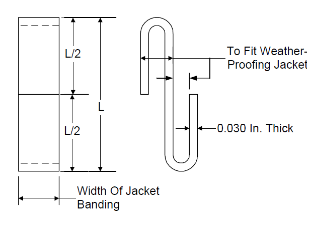
NOTE: Length (L) to equal overlap of jacketing per Section 10.
FIGURE 2 INSULATION STUDS AND CLIPS
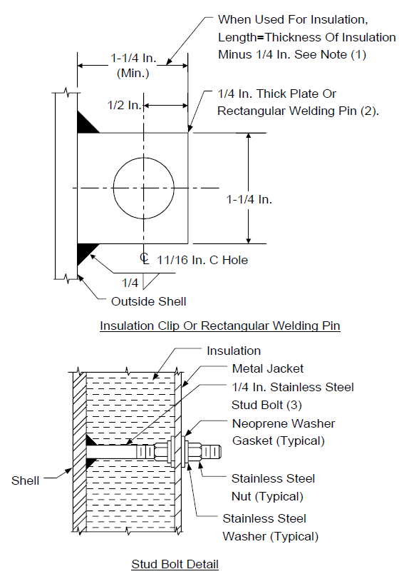
NOTES:
- For insulation thickness less than 1 1/2 inches, use 1/2 inch nut or U-shaped 1/4 inch diameter rod welded to vessel.
- See Section 8.0 for material requirements.
- Studs are spaced on 14 inch centers circumferentially, but in no case shall there be less than 3 studs. Install studs below support rings.
FIGURE 3 INSULATED FIXED ROOF TANKS
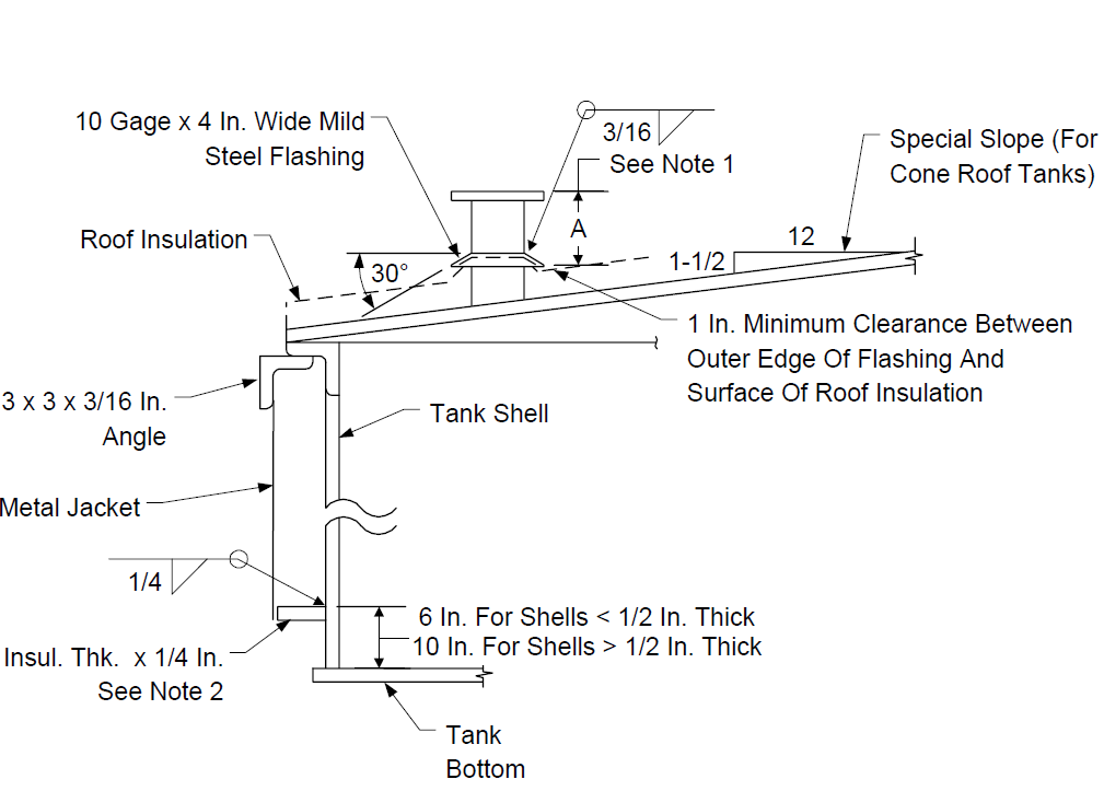
NOTES:
- Dimension "A" = API-650 recommended roof nozzle and roof manhole projection.
- Circumferential support bars shall not be continuous but shall be 8 feet long (max) with 1/2 inch gaps between adjoining pieces.
- Fire tube and heating coil connections shall be boxed in as shown regardless of their height ("B") above tank bottom.
- Weld requirements for Insulation and fireproofing supports shall comply with EP 9-1-2, EP 9-2-1and EP 9-4-1as applicable.
FIGURE 4
SHELL-TO-ROOF ANGLE
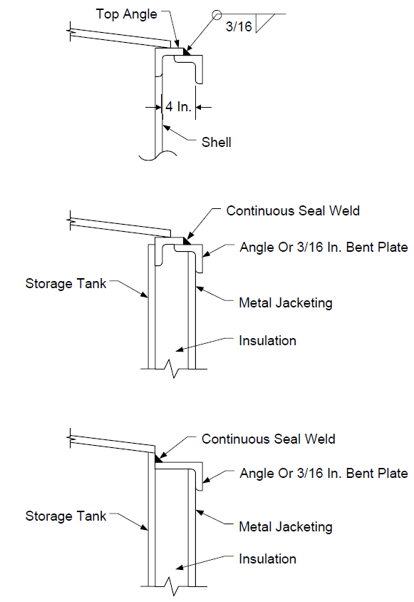
FIGURE 5
DETAILS FOR INSULATED FIXED ROOF TANKS
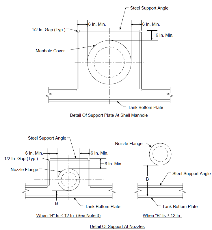
NOTE: For notes see Figure 3.
FIGURE 6
SPACING OF CLIPS ON SPHERES
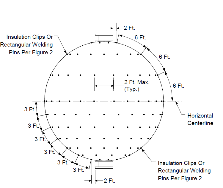
NOTE:
Dimensions shown are maximum and shall be measured on periphery.
FIGURE 7
"BELT LOOP" DETAIL
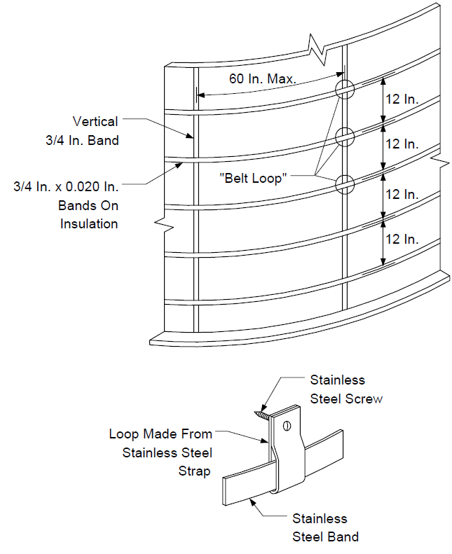
FIGURE 8
TANK PENETRATION INSULATION DETAILS
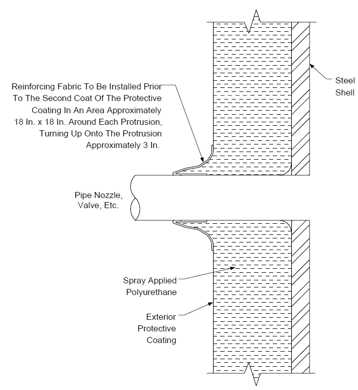
FIGURE 9

TERMINATION OF POLYURETHANE FOAM
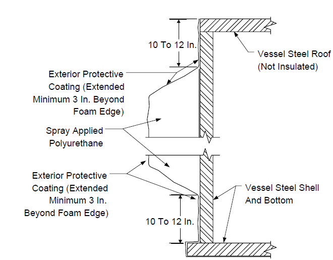
FIGURE 10
EXPANSION JOINT AND BONDING DETAILS
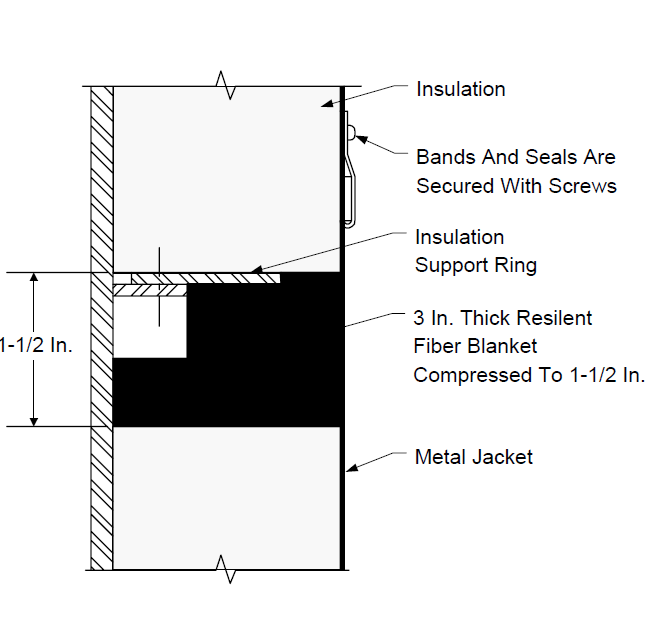
FIGURE 11
STIFFENER RING INSULATION
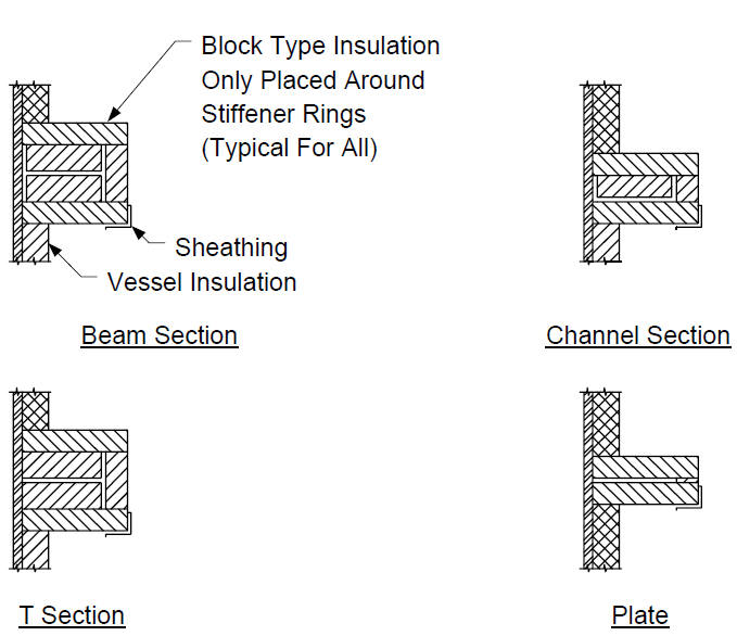
FIGURE 12
SHEATHING AT STIFFENERS
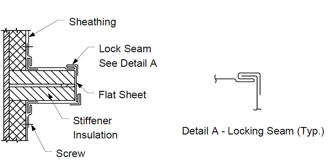
FIGURE 13
FLASHING AT NOZZLES AND OTHER PROJECTIONS
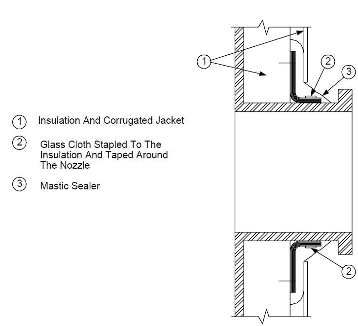
NOTE:
Care should be taken to insure that there is no path for moisture between the corrugations on the underside of the nozzle.
FIGURE 14
FOAM SURFACES COMPARED
© 2026 Inflection Point Engineering, LLC. All rights reserved. The content of this page — including calculation methods, reference data, written analysis, interactive tools, and source code — is the intellectual property of Inflection Point Engineering, LLC and is protected under applicable copyright, trademark, and trade secret laws. Unauthorized reproduction, redistribution, modification, or derivative use in whole or in part is prohibited without prior written consent.
Disclaimer. This material is provided for informational and educational purposes only and does not constitute professional engineering advice. Calculations, reference data, and methodologies are based on published standards and accepted engineering practice but are not a substitute for engineering judgment, site-specific analysis, or review by a licensed Professional Engineer. Inflection Point Engineering, LLC makes no warranties, express or implied, regarding the accuracy, completeness, or fitness for a particular purpose of any content presented here, and shall not be liable for any direct, indirect, incidental, or consequential damages arising from its use. Users assume all risk associated with applying this content to real-world design, operations, or decisions.
© 2026 Inflection Point Engineering, LLC. All rights reserved.