 Section 11 — Refractory, Insulation & Fireproofing
Insulation Application - Vessels and Equipment
IPE Engineering Practice IPE-EP-11-3-3
Document number: IPE-EP-11-3-3 · Section: 11 — Refractory, Insulation & Fireproofing
Figure 10 Attachment of Insulation To Top of Vertical Vessels 28
Figure 11 Attachments of Insulation To Horizontal Vessel Heads and Bottom Head
of Vertical Vessels Without Skirt 28
Figure 12 Typical Heat Exchanger Details When Removable 29
Figure 13 Typical Heat Exchanger Details 30
Figure 14 Stiffener Ring Insulation 31
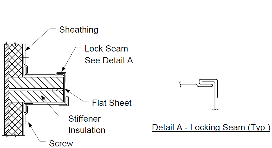
Figure 15 Sheathing At Stiffeners 31
1.0
1.1
1.2
1.3
1.4
1.5
1.6
2.0
SCOPE
This Practice governs the mandatory requirements for materials and application of external insulation for equipment operating above the atmospheric dew point.
This Practice is not applicable to boilers, fired heaters, or storage tanks.
Any deviation from this Practice must be approved by the procedure described in EP 1-1-3.
This Practice is appropriate for attachment to an inquiry or purchase document when accompanied by the referenced IPE Engineering Practices and the completed data sheets, as required.
An asterisk (*) indicates that a decision by the Owner is required, or that additional information shall be furnished by the purchaser.
A revision bar indicates all changes made to this Revision.
REFERENCES
The latest edition of the following standards and publications are referred to herein.
STANDARDS AND PUBLICATIONS
| IPE Engineering Practices |
|---|
| EP 1-1-3 Deviations to IPE Engineering Practices EP 7-1-5 Welding Requirements for Pressure Vessels EP 10-3-1 Shop Painting EP 11-2-1 Fireproofing EP 11-3-5 Removable/Reusable Insulation EP 11-3-6 Insulation of Flanged Joints and Valves in Hot Service |
| ASTM |
| A167 Specification for Stainless and Heat-Resisting Chromium-Nickel Steel Plate, Sheet, and Strip B209 Specification for Aluminum and Aluminum-Alloy Sheet and Plate C449 Mineral Fiber Hydraulic-Setting Thermal Insulating and Finishing Cement C533 Calcium Silicate Block and Pipe Thermal Insulation C552 Cellular Glass Block and Pipe Thermal Insulation C592 Mineral Fiber Blanket Insulation C610 Expanded Perlite Block and Pipe Insulation C612 Mineral Fiber Block and Board Insulation C795 Wicking Type Thermal Insulation for Use Over Austenitic Stainless Steels C892 High Temperature Fiber Blanket Thermal Insulation C929 Handling, Transporting, Shipping, Storage, Receiving, and Application of Thermal Insulation Materials to be Used Over Austenitic Stainless Steel E84 Surface Burning Characteristics of Building Materials |
DEFINITIONS
- Contractor - Company or business that agrees to furnish materials or perform specified services at a specified price and/or rate to the Owner.
- Design Temperature - Shall be the highest temperature reached during operation, steamout, or regeneration.
- Equipment - Each pump, compressor, product accumulator vessel, pressure relief device, valve, sampling connection system, open-ended valve or line, flange or other connector in VOC service, or devices or systems required by this Practice.
- Fire Exposed Area - An area is considered fire exposed if it is horizontally within 30 feet of any fire potential equipment or of the limits of a potential pool or stream of burning liquid, or if it is vertically within 40 feet above any level at which a fire may be initiated. When a fire can be started above grade, the distance below (to grade) is also considered fire exposed.
- Inspector - A Inflection Point Engineering, LLC appointed engineer or inspector.
- Low Melting Point Alloys - Shall include all alloys with a melting point below 1800F. This includes the aluminum, copper, and magnesium alloys.
- Manufacturer - The recipient of a direct or indirect purchase order for materials and/or equipment. In this context, a direct order is one issued to a manufacturer by a contractor or the Owner. An indirect order is one issued to a manufacturer by a vendor (recipient of a direct order) for materials, fabricated components, or subassemblies.
- Owner - Inflection Point Engineering, LLC.
- Owner's Engineer - A Inflection Point Engineering, LLC appointed engineer.
- Purchaser - The party placing a direct purchase order. The purchaser is the Owner's designated representative.
DRAWING AND INSULATION SCHEDULES
- (*)Drawing and insulation schedules shall be supplied to the contractor by the Owner's Engineer and shall contain the following information:
- Equipment (designated by equipment number) to be insulated and extent of insulation if only partial coverage is required.
- Equipment that requires special insulation to prevent stress corrosion cracking of austenitic stainless steel.
- Type, total thickness, and number of layers of insulation required.
- Design temperatures.
- Extent of insulation designated as fireproofing.
- Equipment that requires insulation only for personnel protection.
- Equipment to be heat traced.
- Type of insulation weatherproof covering, and external coating as required.
- Designated areas and requirements for surface preparation and painting.
- Areas specified to be insulated for noise control or combined thermal and noise control.
- Manways and flanges to be insulated.
- Areas where insulation is to be both removable and reusable.
- Type and location of expansion joints.
- Surfaces specified to be insulated for winterizing.
- Documentation requirements for insulation system are shown in Table 1.
DOCUMENTATION
- (*)Proposal Information
The following data as applicable shall be submitted to purchaser for approval by the Owner's Engineer.
- Product specifications.
- Material storage requirements, including shelf life and temperature.
- Design and application details of expansion joints.
- Repair procedures for damaged areas.
- Inspection and testing procedures.
- Recommended safety precautions, such as the proposed method of electrical grounding of equipment (i.e., blast cleaning and spray application).
- Contractor Specification
The Owner's Engineer shall supply a supplemental job specification to the insulation contractor. The job specification shall include all applicable drawing and insulation schedules, material specifications, and all obligations and responsibilities required for the job.
ACCEPTABLE MATERIALS
- General
- Vessels and equipment with design temperatures at and above 450F, in fire exposed areas, used as fire protection, or areas of high maintenance traffic shall be calcium silicate.
- Bottom heads on vertical vessels with skirts shall be insulated with mineral wool blanket, 8 pound density with #20 gauge hexagonal mesh galvanized wire (do not use galvanized wire on stainless steel) on both sides for temperatures up to 1200F.
- Irregularly shaped equipment may be insulated with removable insulation per EP 11-3-5 or insulating cement rated for 1200F (min).
- Vessels and equipment with design temperatures below 450F shall be insulated with one or more of the following materials:
- Calcium Silicate.
- Cellular glass (preferred when operating temperatures are below 250F, or cycle below 250F).
- Mineral Wool (vertical vessel shells and bottom heads).
- Rigid and Resilient Insulation
- Calcium Silicate block insulation shall be suitable for a continuous operating temperature of 1200F and comply with ASTM C533, Type I requirements. For fire exposed areas or higher temperatures, calcium silicate shall be manufactured to withstand at least 1800F and shall comply with ASTM C533, Type 2.
- Mineral Wool shall have a neutral pH, a nominal density not less than 8 lb/cu.ft. and be suitable for a continuous operating temperature of 1200F, except as noted. Additional requirements are:
- Blankets shall conform to ASTM C592, Class II. They shall be faced with wire mesh on both sides. Mesh shall not be galvanized for use on austenitic steel surfaces.
- Blocks and boards shall conform to ASTM C612, Type 5. The minimum nominal density shall be 10 lb/cu.ft. for face temperatures up to 1200F, and 13lb/cu.ft. up to 1800F
- Cellular glass shall conform to ASTM 552 and is limited to a maximum service temperature of 450F.
- Perlite shall comply with ASTM C610, Type II material, and shall have a sodium silicate binder. The material shall also be subjected to a high temperature test (1200F), and be checked for smoking, charring, cracking, and other signs of physical deterioration.
- Alumina silica ceramic fiber blanket shall conform to ASTM C892 with a density of 8 lb/cu.ft. and a maximum use temperature of 2300F.
- Insulating cement shall be mineral fiber ASTM C449. Cement shall set to a hard smooth monolithic finish.
- Expansion joint materials shall consist of compressible insulation suitable for the operating temperature and, for face temperatures above 450F, shall be without binders.
- Insulation Coverings
- Weatherproofing jacket for equipment in non fire exposed areas shall be aluminum according to the following:
- Sheets and rolls shall be 1-1/4 inch corrugated 0.016 inch thick.
- Flat stucco embossed aluminum, .019 inches thick, shall be used on heads, transitions, stiffener rings, and flashing.
- Aluminum alloy to be ASTM B 209, Type 3003 or 5005.
- At the discretion of the Owner's Engineer, jacketing in nonfire exposed areas may be upgraded to stainless steel, per paragraph 6.3.2.
- Weatherproof covering for fire exposed areas and equipment of low melting alloys shall be 0.01inch thick stainless steel ASTM A 167, Type 316. Covering steel shall be according to the following:
- Sheets and rolls shall be 0.01 inch thick with 1-1/4 inch corrugations in the long direction.
- Formed heads, transitions, stiffener rings, and flashing shall be 0.010 inch thick, smooth, interlocking gore type.
- Fireproofing mastic shall be a breather type, asbestos free, with a flame spread of 4 or less (Vimasco WC-1 or equal).
- All jacketing materials shall have a vapor barrier of colored converted epoxy, colored polyethylene, or 50-pound polyethylene-kraft paper moisture barrier 100 percent bonded to the inside surface. When specified on the insulation schedules the outside of the jacketing shall be coated with a color converted epoxy.
- Insulating and Finishing Cement shall be composed of mineral fiber pellets and insulating fillers, blended with hydraulic setting binders and corrosion inhibitors. Cement shall set to a smooth, hard monolithic finish.
- Insulation systems on low melting alloys (such as aluminum), or on equipment where the system is considered as fireproofing, shall be capable of withstanding the force of firehose stream impingement.
- Elastomeric coatings shall be used over cellular glass insulation when metal jackets are not provided.
- Applied coatings of asphaltic (mastic) or elastomeric (such as butyl rubber) materials shall comply with the following:
- A flame spread classification of not more than 25 per ASTM E 84.
- A demonstrated resistance to solar radiation.
- Flexible at the lowest temperature to which they are exposed.
- Compatible with the insulation materials.
- Mastics shall be of the breathing emulsion type.
- Mastic Weathercoat shall be a vinyl acrylic Childers Vicryl or equal.
- Accessories
- Bands shall be stainless steel, Type 316, annealed temper. Sizes shall be 3/4 inch wide by 0.020-inch minimum thickness, with wing type seals. Breather springs shall be used where required for expansion.
- Bands shall be marked (either stamped or color coded blue as specified by the plant) to indicate nonasbestos containing insulation. Bands on asbestos containing insulation shall be color coded yellow.
- Seals shall be stainless steel to match bands (regular-wing type, long shank).
- Wire shall be 14 BWG stainless steel, Type 316 annealed temper.
- Reinforcing for applied coatings shall be as follows:
- Wire mesh shall be 1 in. hexagonal woven wire poultry mesh, 0.035 inch (20 BWG) minimum wire diameter. Wire shall be either stainless steel or Monel. The mesh shall be laced into place with wire at least 0.08 inch diameter of the same material.
- Glass Fabric shall be per coating manufacturer's recommendations for reinforcing fabric in mastic finishes. If not specified, use 10 x 10 open mesh, Childers Chil-Glas #10 or equal.
- Sheet metal screws for securing metal to metal shall be Number 8 by 1/2-inch long self tapping, Type 304 stainless steel, with neoprene gaskets.
- Breather springs shall be stainless steel to match bands, 5-inch minimum expansion, and a 110 pound load limit (min). Double springs (INSUL-MATE ES-7 RPR Products, Inc., or equal) shall be used for jacketing.
- Flashing Compound where temperatures exceed 250F. shall be a high temperature asphalt for weatherproofing applications.
- Sealer/flashing mastic shall be nonshrinking permanently flexible, less than one perm water vapor per 1/16-inch thickness.
- S-clips for jacketing on vertical vessels shall be stainless steel, Type 316 annealed temper, see Figure 1.
- Welded studs for insulation jacket supports shall be stainless steel, Type 316 (see Figure 2 ).
- Insulation rectangular welding pins (per Figure 2). See paragraph 8.6 for material requirements.
SPECIAL REQUIREMENTS
- (*)In areas where frequent maintenance will require removal of the insulation, as specified by the Owner's Engineer and shown on drawings, the system shall be designed to allow easy removal and reuse. These removable covers shall be designed to remain intact during a fire and subsequent firewater impingement. They shall also be capable of withstanding normal mechanical abuse during frequent removal, storage, and reinstallation. Removable insulation shall comply with the requirements in EP 11-3-5.
- (*)The following items shall not be insulated unless specified by the Owner's Engineer.
- Cooling side (water side) surfaces of coolers and condensers.
- Vessels components with internal refractory/insulation.
- Flanges.
- Compressors.
- When flanges qualify for insulation they shall be insulated per EP 11-3-6.
INSULATION SUPPORTS
- Insulation supports for hot equipment shall be per Figure 3 through Figure 7 for vertical vessels and Figure 6 for horizontal vessels. For special cases where it is either not permissible or not practical to weld insulation supports to a vessel, special supports (secured to the vessel with tie wires or bands) shall be detailed on the drawings and approved by Owner's Engineer.
- Support rings for use on vertical vessels shall be spaced no more than 8 feet apart. One shall be located at or below the bottom tangent line.
- Horizontal vessels (over 6 feet in diameter) shall have a bar along the centerline of the vessel.
- One quarter (1/4) inch diameter rods about the periphery of horizontal vessel heads shall be used to permit radial banding of blocks on the heads (see Figure 8).
- See Figure 4 for support ring details for vessels with design temperatures less than 450F. See Figure 5 for support ring details for vessels with design temperatures of 450F and greater. See Figure 8 for horizontal vessel support rings details.
- Vessel attachments required for support of insulation and fireproofing shall be as follows:
- Support clips welded to the vessel shall be fabricated from the same material as the vessel.
- Insulation support ring material shall be:
- Carbon steel for carbon steel and low alloy vessels with design temperatures of 800F and less.
- The same as the vessel material for all other cases.
- Heat treated items requiring welding pins, clips or studs shall have pins installed prior to heat treatment.
APPLICATION
- General
- Pressure tests on vessels and equipment shall be completed before insulation is installed.
- Care shall be taken to avoid contact between dissimilar materials which might cause galvanic corrosion (i.e. aluminum in contact with steel, etc.).
- Insulation shall be kept dry and protected against the elements during storage and all stages of application until the weatherproofing has been installed.
- Surface Preparation
- (*)Surface preparation including any washing of stainless steel surfaces, and primer painting, will be done, as specified, and shall comply with EP 10-3-1.
- Surfaces to be insulated shall be dry, and shall have foreign matter removed by solvent cleaning. Unpainted surfaces also shall be free of loose scale.
- Projections
All projections from surfaces shall be insulated completely or to the maximum practical extent (For example; stairway clips shall be insulated to the attachment point of the stairtread; nozzles shall be insulated to the connective flange.
- Access and Clearance
- A minimum clearance of 2 inches, between the outside of any insulation and adjacent equipment, piping, or structural members shall be maintained. This clearance shall take into account the thickness of any fireproofing coating or insulation applied to such adjacent equipment, piping, or structural members.
- Insulation on both sides of flanged joints shall be tapered to permit stud removal without damage to the insulation.
- Edges of insulation openings such as around manholes, nozzles, cutouts for stud removal, pipe supports, and other attachments, shall be sealed with flashing or metal jacketing to prevent water from entering. Metal covers shall be used if temperatures are beyond the usable range of weatherproofing coatings. On partially insulated vessels, the exposed end of the insulation shall butt up to or against a seated metal ring to prevent water ingress and corrosion under insulation.
- Vessel nameplates (including code inspection plates) shall not be insulated. Insulation surrounding these plates shall be beveled away from such markings and sealed to prevent water from entering.
- Installation
- All insulation shall be installed butted together.
- Each layer of insulation shall be installed with transverse or longitudinal joints staggered, and secured in place with bands.
- If more than one layer of insulation is applied, each layer shall be secured in place, and joints of each layer offset.
- All gaps shall be filled with insulating cement. Except, when insulating stainless steel use blanket insulation to point-up the cracks.
- Spacing of studs, clips or pins for securing insulation shall be on approximately 16 in. centers for blanket insulation. Block insulation shall be installed with no less than 2 studs (clips or pins) per block.
- When dual layer insulation systems employing different insulation materials are used for combined thermal and noise control, the mineral wool shall be installed as the outer layer.
- Install each panel of board or blanket insulation in a slightly compressed condition in both directions.
- Insulation shall be installed in two staggered layers of nearly equal thickness if:
- The insulation design temperature is above 600F. and insulation thickness is greater than 2 inches.
- Insulation is used for fireproofing.
- Vessels and Equipment
- See Figure 6 for "Hot Box" details for vertical vessels operating above 450F.
- Block insulation on vessel and exchanger shells shall be secured in place with bands spaced on 12 inch centers (max). The blocks shall be carefully mitered to fit all surfaces without rocking. Where double layers are used the inner layer shall be secured with wire or bands on 18 inch spacing (max). Weatherproofing shall be supplied over the insulation.
- On vessels operating above 450F, breather springs shall be installed in the bands securing the outside and inner layers of insulation.
- With vessel in the cold condition, each spring shall be installed in tension to produce a 3/4-inch spring expansion.
- Vertical vessels having insulation design temperatures above 450F. shall have expansion joints installed below all support rings except at the bottom support. Installation shall be per Figure 9.
- For vessels and exchangers block insulation shall be used except when under 24 inches in diameter, preformed pipe insulation shall be used.
- Top and bottom of exposed heads on vertical vessels shall be insulated with blocks, secured with bands attached to a floating ring on the top and to a circumferential support ring at the tangent line. Band spacing shall be on 12 inch minimum centers at the tangent line. (See Figure 10 and Figure 11 ).
- The bottom heads on vertical vessels with support skirts shall be insulated with mineral wool blanket supported with mesh both sides, impaled on welding pins and secured with wire. Weatherproof the bottom head per Section 10.4. Insulation in fire exposed areas shall be jacketed per Section 11.0.
- Heads on horizontal vessels, shall be insulated with blocks, secured with bands attached to a floating ring at the center of the head and to a circumferential ring at the tangent line. See Figure 8 and Figure 11.
- See Figure 12 for typical heat exchanger insulation details when removable insulation covers are specified by the Owner's Engineer.
- Unless removable insulation covers, per EP 11-3-5, are specified by the Owner's Engineer, shell covers on exchangers shall be insulated with blocks, secured with bands attached to the 1/4 inch diameter circumferential rod provided on the shell cover by others. Band spacing shall be 12 inches maximum at the tangent line. A strip 12 inches wide at the body flange shall be insulated with reusable insulation to facilitate bolt removal. See Figure 13 for details.
- Unless removable insulation covers, per EP 11-3-5, are specified by the Owner's Engineer, channel covers on exchangers shall be insulated as follows. A 1/4 inch insulation support ring and 1/8 inch thick plate cover will be provided by the fabricator. The plate cover shall be removed, the void shall be snugly filled with block or blanket insulation, and the cover replaced and continuously welded in place. Welding of the cover plate shall be the responsibility of the insulating contractor. See Figure 13.
- Double pipe exchangers, when insulated, shall be insulated as a single unit and shall be covered with a combination of pipe and block insulation securely banded or wired in place.
WEATHERPROOFING
- General
- Insulation must be thoroughly dry at time of weatherproofing.
- The type of insulation covering will be specified, on the drawings and insulation schedules.
- Metal Jackets
- Use corrugated sheets on vertical vessels and rolls on horizontal or inclined vessels.
- Metal jacketing for vertical vessels shall be supported on welded studs (See Figure 2 ). Studs shall be spaced on 14 inch centers circumferentially but in no case less than 3 studs shall be installed. Studs shall be installed below support rings on 24 foot (maximum) vertical centers at locations where adjacent courses of jacketing will overlap.
- On vertical vessels, for those courses where welded studs are not required, support at the circumferential overlap shall be provided by "S" clips fabricated per Figure 1. S-clips shall be spaced on 14 inches centers (max).
- Laps of jackets shall be positioned to shed water. Minimum lap (horizontal and vertical) shall be as shown in Table 2, but in no case less than 2 full corrugations.
- Jackets shall be lapped, or sealed where not practical to lap, to prevent entrance of water. Insulating cements shall not be used for sealing purposes. This includes lapping the bottom course over the lower insulation support ring of vertical vessels.
- Jacket attachment shall be designed to hold the jacket in place for the condition of design wind speed (fastest-mile).
- Metal covering shall be secured with bands spaced not less than one band on each on each circumferential lap and one at the middle of each sheet, but not to exceed 12 inches on center. On vertical surfaces, secure bands to sheets with screws on not more than 5 foot centers to prevent sliding (See Figure 9).
- On horizontal vessels, shell and tube and double pipe exchangers, circumferential bands shall be installed on 12 inch centers and shall be machine-stressed and fastened under tension.
- Metal screws shall be installed on longitudinal seams centered between all bands.
- On vessels operating above 450F, breather springs shall be installed in the banding. Breather springs shall be equally spaced. The number of springs required shall be per Table 3.
- On vertical and horizontal vessels, the junction between weatherproofing mastic on the heads and the metal jacket on the shell shall be sealed with a mastic filler.
- The top heads on vertical vessels and exchanger equipment shall have a metal cover fabricated with weatherproof seams. Secure gore sections of fabricated head-jackets with screws on not more than 6 inch centers. The cover shall extend a minimum of 3 inches down over the shell jacketing. Screws shall be installed on 6 inch centers around the circumferential overlap.
- Stiffener rings on vertical vessels shall be insulated and weatherproofed in accordance with Figure 14 and Figure 15.
- For insulation design temperatures below 400F, apply a 1/4-inch minimum fillet of sealer/ flashing mastic (Paragraph 6.4.9) to weatherproof small openings between the jacket and vessel surfaces such as at nozzles, manholes, etc. For temperature above 400□F, metal flashing shall be used. Extra precautions must be taken to insure good fit-up.
- Mechanical Equipment
- If those insulating materials specified in this practice cannot be economically applied, insulating cement may be installed but the thickness shall be increased 50 percent.
- Pumps and turbines insulated with cement shall be finished as follows: a tack coat of mastic shall be applied to the outer surface of insulation, then fabric shall be imbedded into the mastic. The fabric shall lap at least 3 inches at all joints and shall be wrinkle-free. A 1/8 inch thick coat (dry film thickness) of mastic shall then be applied over the fabric. After drying, no porosity shall exist in coating.
- Elastomeric Coatings
- Elastomeric coatings shall be reinforced with synthetic fiber fabric when cellular glass insulation is used.
- (*)Total elastomeric coating film thickness shall be per the coating manufacturer's recommendations. Coatings shall be applied in a minimum of two coats. Recommended total film thickness is 30-40 mils dry (64-86 mils wet). The final proposed thickness shall be approved by the Owner's Engineer prior to application.
- Reinforcing fabric used in conjunction with the coating shall be applied without wrinkles; metal fasteners (e.g., staples) shall not be used to hold fabric.
- Application of multi-coat system:
- Immediately after application of the first coat, and while still wet, a layer of reinforcing fabric shall be pressed smoothly into the coating. Fabric overlap shall be 1 to 2 inches.
- After a minimum of 4 hours drying time, the 2nd coating shall be applied.
- Double layers of fabric shall be used at joints of attachments, or other configurations, requiring a smooth transitions of the weatherproofing coatings.
- Mastic Coatings
- Where an insulating cement is permitted as an alternative to a metal jacket, this finish shall be made as follows: The insulating cement shall be installed, and the finished surface shall be weatherproofed with a mastic coating.
- (*)Mastic coatings shall be reinforced and the final thickness shall be per the coating manufacturer's recommendations. A minimum thickness of 1/8 inch thick (dry film) is recommended. The final proposed thickness shall be approved by the Owner's Engineer prior to application.
- Mastic shall be used on the bottom head on vertical vessels with support skirts.
- Application shall be per the manufacturer's recommendations. As a minimum, when mastic is used there shall be a tack coat of mastic applied over the insulation, followed by a layer of fabric installed wrinkle free. Over the fabric a 1/8 inch layer, when dry, of mastic weather coat shall be trowelled to a smooth finish. After drying, no porosity shall exist in coating.
- This finish shall extend approximately 2 inches under the adjacent weatherproofing jacket.
- Vertical joints between mastic and jacketing shall be sealed to prevent entrance of moisture.
- Weatherproofing with mastic and fabric shall be done so that all seams are completely covered.
APPLICATION FOR FIRE PROTECTION
Application of combined thermal insulation and fireproofing shall be per Section 9.0 and 10.0 with the following additions:
- Insulation used to fireproof equipment shall be installed in two layers regardless of the insulation design temperature.
- A band shall be installed not more than 2 inches above all rows of studs supporting fireproofing jacket on vertical cylindrical vessels.
- (*)Fireproofing mastic when specified by Owner's Engineer, shall be reinforced with wire mesh in place of stainless jacketing.
- Jacketing shall be designed to remain intact during firewater impingement.
- (*)Jacketing shall be color coded, as specified by Owner's Engineer.
INSPECTION
- Compliance with governing specifications shall be checked by the Inspector during the course of installation of the insulation system.
- Work shall not proceed with the next step in the insulation system sequence (i.e., surface preparation, priming, insulation, weather barrier application) until the previous work has been inspected and approved.
- Hammer testing of pins is required to insure integrity of welds. Testing must be done immediately upon completion of welding.
13.0 TABLES
TABLE 1 DOCUMENTATION REQUIREMENTS FOR INSULATION APPLICATION PER EP 11-3-3
| Item | Description | Format | As-Built |
|---|---|---|---|
| 1 | Product specifications | See EP 2-5-2 | Yes |
| 2 | Material storage requirements, including shelf life and temperature. | See EP 2-5-2 | Yes |
| 3 | Design and application details of insulation expansion joints. | See EP 2-5-2 | Yes |
| 4 | Repair procedures for damaged areas. | See EP 2-5-2 | Yes |
| 5 | Inspections and testing procedures. | See EP 2-5-2 | Yes |
| 6 | Recommended safety precautions, such as proposed method of electrical grounding of equipment (i.e, blast cleaning and spray application). | See EP 2-5-2 | Yes |
| 7 | Contractor Specification The Owner's Engineer shall supply a supplemental job specification to the insulation contractor. The job specification shall include all applicable drawing and insulation schedules, material specifications and all obligations and responsibilities required for the job. |
See EP 2-5-2 | Yes |
TABLE 2
MINIMUM LAP FOR JACKETING
| Vessel or Equipment Diam. | Minimum Lap |
|---|---|
| 24 inches >24 inches |
inches inches |
TABLE 3
NUMBER OF EXPANSION SPRINGS REQUIRED PER BAND
| Diameter Section in Feet | Insulation Design Temperature RangeF | Insulation Design Temperature RangeF | Insulation Design Temperature RangeF | Insulation Design Temperature RangeF |
|---|---|---|---|---|
| 450-600 | 601-800 | 801-1000 | 1001-1200 | |
| 4 to 8 | - | 1 | 1 | 2 |
| 8 to 12 | 1 | 1 | 1 | 2 |
| 12 to 20 | 1 | 2 | 2 | 3 |
| 20 to 26 | 2 | 3 | 3 | 4 |
| 26 to 30 | 3 | 3 | 4 | 5 |
14.0 FIGURES
FIGURE 1 "S" CLIP
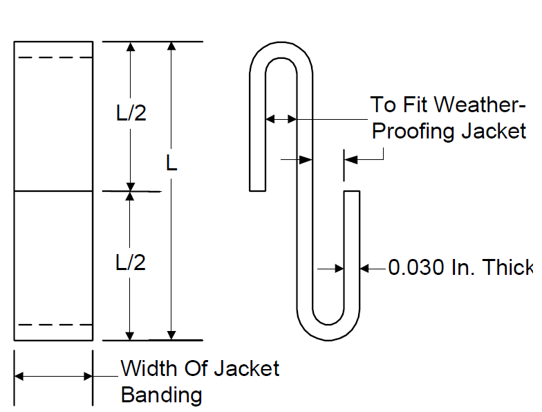
NOTE: Length (L) to equal overlap of jacketing per Section 10.
FIGURE 2 INSULATION STUDS AND CLIPS
NOTES:
- For insulation thickness less than 1 1/2 inches, use ½-inch nut or U-shaped ¼-inch diameter rod welded to vessel.
- See Section 8 for material requirements.
- Studs are spaced on 14-inch centers circumferentially, but in no case shall there be less than 3 studs. Install studs below support rings.
FIGURE 3
INSULATION DETAILS FOR VERTICAL VESSEL
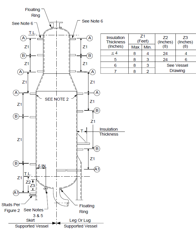
FIGURE 4
INSULATION SUPPORT DETAILS FOR VERTICAL VESSELS WITH A DESIGN TEMPERATURE 450F AND LESS
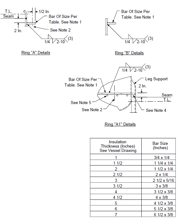
FIGURE 5
INSULATION SUPPORT DETAILS FOR VERTICAL VESSELS WITH A DESIGN TEMPERATURE EXCEEDING 450F
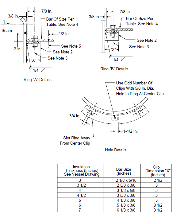
FIGURE 6
SKIRT "HOT BOX" DETAILS AT TEMPERATURES EXCEEDING 450F
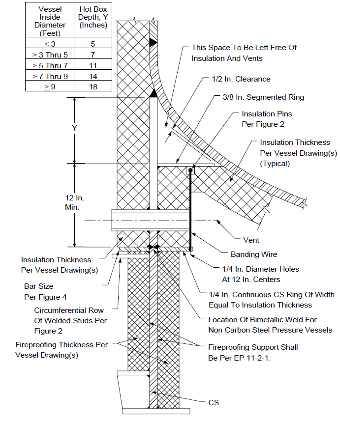
FIGURE 7 LAYOUT OF WELDING PINS
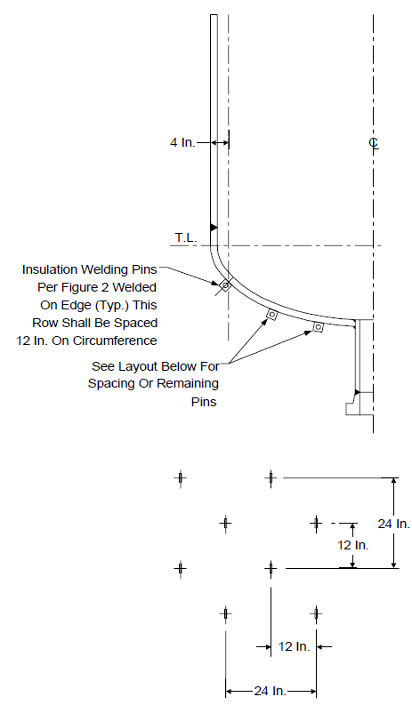
FIGURE 8
INSULATION SUPPORTS FOR HORIZONTAL VESSELS
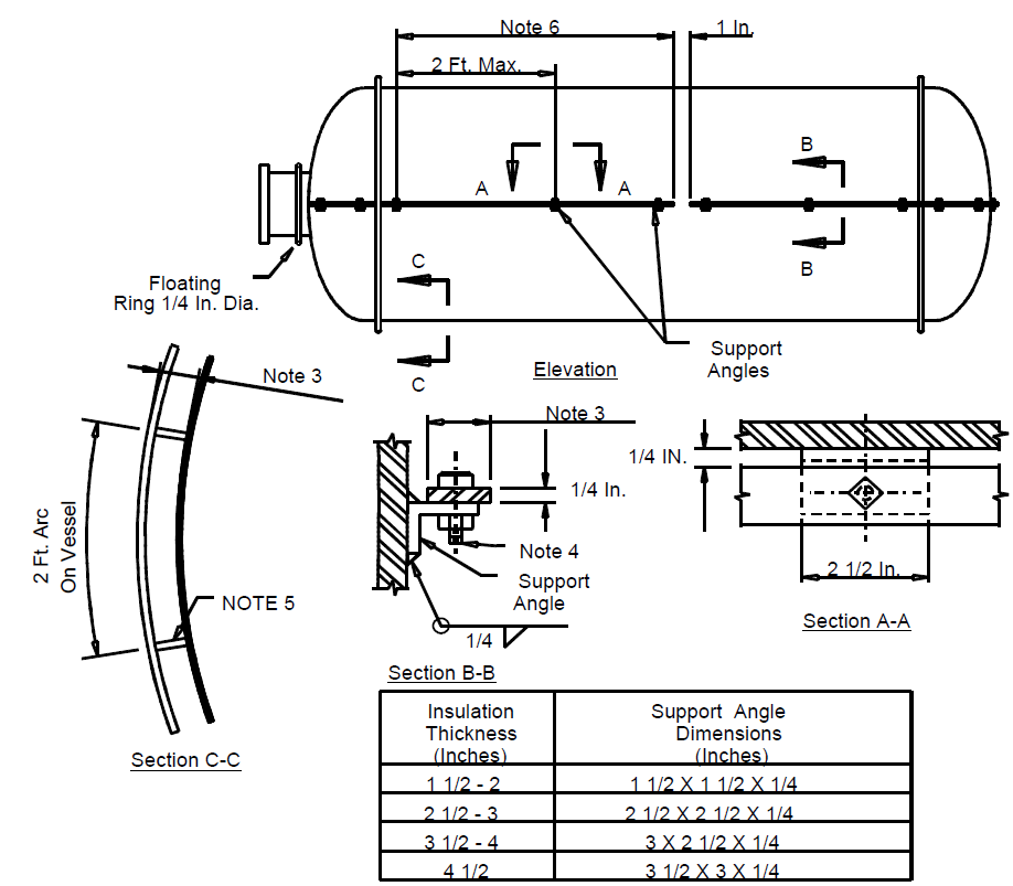
NOTES:
- Welds on support angles must clear vessel seams by at least 2 inches. If seam is on horizontal centerline, lower angle supports to clear.
- The insulation support bar shall not be used on vessels 6 ft. diameter or less
- 1/2 inch less than insulation thickness.
- 1/2 inch bolt in 5/8 inch diameter hole with washer.
- 1 1/4 inch support lugs welded to vessel. See Figure 2. Orient pins so rod can be threaded through hole.
- 6 foot maximum bar length.
FIGURE 9
EXPANSION JOINT DETAILS
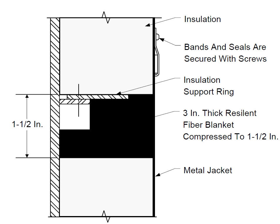
FIGURE 10
ATTACHMENT OF INSULATION TO TOP OF VERTICAL VESSELS
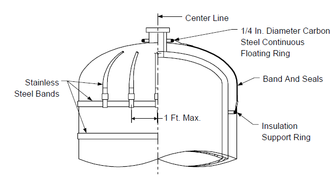
FIGURE 11
ATTACHMENTS OF INSULATION TO HORIZONTAL VESSEL HEADS AND BOTTOM HEAD OF VERTICAL VESSELS WITHOUT SKIRT
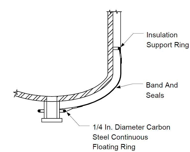
FIGURE 12
TYPICAL HEAT EXCHANGER DETAILS WHEN REMOVABLE
NOTES:
- See EP 11-3-6 for restrictions regarding the use of flange insulation.
- Identify each piece of insulation on outside surface by method approved by Owner's engineer.
- For removable insulation details, see EP 11-3-5.
FIGURE 13
TYPICAL HEAT EXCHANGER DETAILS
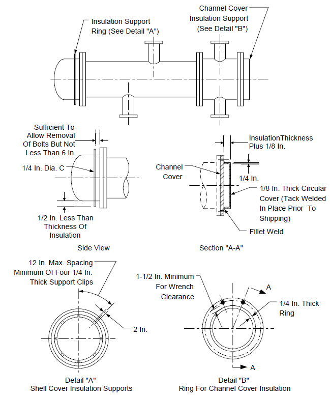
FIGURE 14
STIFFENER RING INSULATION
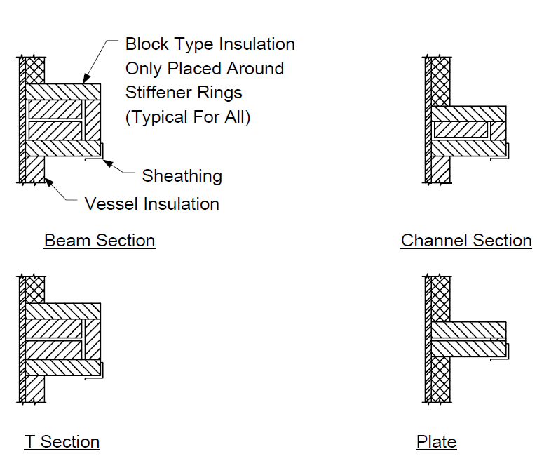
FIGURE 15
SHEATHING AT STIFFENERS
© 2026 Inflection Point Engineering, LLC. All rights reserved. The content of this page — including calculation methods, reference data, written analysis, interactive tools, and source code — is the intellectual property of Inflection Point Engineering, LLC and is protected under applicable copyright, trademark, and trade secret laws. Unauthorized reproduction, redistribution, modification, or derivative use in whole or in part is prohibited without prior written consent.
Disclaimer. This material is provided for informational and educational purposes only and does not constitute professional engineering advice. Calculations, reference data, and methodologies are based on published standards and accepted engineering practice but are not a substitute for engineering judgment, site-specific analysis, or review by a licensed Professional Engineer. Inflection Point Engineering, LLC makes no warranties, express or implied, regarding the accuracy, completeness, or fitness for a particular purpose of any content presented here, and shall not be liable for any direct, indirect, incidental, or consequential damages arising from its use. Users assume all risk associated with applying this content to real-world design, operations, or decisions.
© 2026 Inflection Point Engineering, LLC. All rights reserved.