 Section 11 — Refractory, Insulation & Fireproofing
Insulation Design
IPE Engineering Practice IPE-EP-11-3-1
Document number: IPE-EP-11-3-1 · Section: 11 — Refractory, Insulation & Fireproofing
SCOPE
- This Practice covers the mandatory requirements governing the design and material selection criteria for hot service thermal insulation systems used on external surfaces of equipment (including piping and tankage) under the following operating conditions:
- A temperature above the atmospheric dewpoint, and
- Not more than 10% of the time below the atmospheric dewpoint.
- The requirements of this Practice also apply to acoustic insulation systems.
- Any deviation from this Practice must be approved by the procedure described in EP 1–1–3.
- A revision bar indicates all changes made to this Revision.
2.0 REFERENCES
The latest edition of the following standards and publications are referred to herein.
STANDARDS AND PUBLICATIONS
| IPE Engineering Practices |
|---|
| EP 1–1–3 Deviations to IPE Engineering Practices EP 10–2–1 Material Requirements for Aggressive Environmental Services EP 10–3–1 Shop Painting EP 10–3–3 Corrosion Protection for Underground Pipe EP 11–2–1 Fireproofing EP 11–3–2 Insulation Application - Piping EP 11–3–3 Insulation Application - Vessels and Equipment EP 11–3–4 Insulation Application - Storage Tanks and Spheres EP 11–3–5 Removable/Reusable Insulation EP 11–3–6 Insulation of Flanged Joints and Valves in Hot Service EP 14–1–1 Winterization |
| API |
| Std 620 Design and Construction of Large, Welded, Low–Pressure Storage Tanks Std 650 Welded Steel Tanks for Oil Storage Pub 941 Steels for Hydrogen Service at Elevated Temperatures and Pressures in Petroleum Refineries and Petrochemical Plants Std 2510 Design and Construction of Liquefied Petroleum Gas Installations (LPG) |
| ASTM |
| C332 Specification for Lightweight Aggregates for Insulating Concrete C795 Wicking Type Thermal Insulation for Use Over Austenitic Stainless Steels E84 Surface Burning Characteristics of Building Materials |
DEFINITIONS
- Aggressive Environmental Service (AES) - Process services which result in material degradation such as cracking, scaling, blistering, and severe pitting and/or corrosion. Examples of such services are hydrogen service, wet hydrogen sulfide, cyanides, caustic, amine, and hydrofluoric acid. AES process fluid are defined in EP 10–2–1.
- Contractor - Company or business that agrees to furnish materials or perform specified services at a specified price and/or rate to the Owner.
- Design Temperature - Shall be the highest temperature reached during operation, steamout, or regeneration.
- Emergency Temperature - Shall be the highest temperature reached and sustained for 30 minutes or longer during emergency or upset conditions.
- Equipment - Each pump, compressor, product accumulator vessel, pressure relief device, valve, sampling connection system, open–ended valve or line, flange or other connector in VOC service, or devices or systems required by this Practice.
- Fire Exposed Area - An area is considered fire exposed if it is horizontally within 30 ft. of any fire potential equipment or of the limits of a potential pool or stream of burning liquid, or if it is vertically within 40 ft. above any level at which a fire may be initiated. When a fire can be started above grade, the distance below (to grade) is also considered fire exposed.
- Hydrogen Rich Service - A service defined as a combination of hydrogen partial pressure and temperature at or below the curve for carbon steel per Figure 1 of API Publication 941, latest edition, and with a hydrogen partial pressure greater than 100 psia.
- Hydrogen Service - A service defined as a combination of hydrogen partial pressure and temperature above the curve for carbon steel per Figure 1 of API Publication 941, latest edition.
- Inspector - A Inflection Point Engineering, LLC appointed engineer or inspector.
- Insulation design temperature for heat conservation - The normal operating temperature shall be used to determine insulation thickness, but material selection shall be based on emergency and design temperatures.
- Low Melting Point Alloys - Shall include all alloys with a melting point below 1800F. This includes the aluminum, copper, and magnesium alloys.
- Manufacturer - The recipient of a direct or indirect purchase order for materials and/or equipment. In this context, a direct order is one issued to a manufacturer by a contractor or the Owner. An indirect order is one issued to a manufacturer by a vendor (recipient of a direct order) for materials, fabricated components, or subassemblies.
- Normal Operating Temperature - Shall be the usual operating temperature. This temperature is shown on the piping line schedules or similar project documents.
- Owner - Inflection Point Engineering, LLC.
- Owner’s Engineer - A Inflection Point Engineering, LLC appointed engineer.
- Piping - Shall include all components in the piping system, except as noted.
- Purchaser - The party placing a direct purchase order. The purchaser is the Owner’s designated representative.
DESIGN CRITERIA
- All temperature design criteria shall require heat loss calculations.
- All insulation material shall be asbestos free.
- Insulation shall be omitted on piping components and sections of equipment where a heat loss is desired or when piping and equipment designs are based on reduced metal temperatures.
- Winterizing and Fireproofing requirements shall be based on need, and as required in EP 14–1– 1 and EP 11–2–1.
- Material selection for thermal insulation systems, including the selection of paints, adhesives, weather coatings, and joint sealers, shall be based on the design temperature and take into account that piping and equipment may be subject to elevated temperatures during steaming out, cleaning, and flushing operations. In addition, the insulation must be good for the maximum emergency temperature.
- Clearances at the design temperature shall conform to the following:
- The clearance between the outside surface of any insulation system on piping, vessels and equipment, and adjacent equipment, piping or structural members (including stairways) shall be not less than 1 inch in the hot condition and 2 inches when cold.
- A minimum clearance of 4 inches between the outside surface of any insulation system on storage tanks and spheres and adjacent equipment, piping or structural members (including stairways) shall be maintained.
- Clearances shall take into account provisions for any fireproofing coatings or insulation applied to such adjacent equipment or structural members.
- Where the specified thickness of insulation for thermal service or personnel protection is increased solely for noise control, piping layout shall be checked to insure that the minimum specified clearance will be maintained.
- Expansion joints for rigid insulation material shall be provided taking into account the following:
- The expansion of the piping or equipment, based on the design temperature of the item.
- The expansion, contraction, or shrinkage of the insulation material, based on the design temperature of the item.
- The resilience of the insulation.
- The method of supporting the insulation.
- Expansion joint material shall consist of compressible insulation suitable for the operating temperature and, for face temperatures above 400F, shall be without binders.
- Insulation shall be provided on equipment and vessels where sudden changes in weather will adversely effect process control or where pour point and/or freezing point is above ambient temperature.
- Piping, equipment and tanks shall be insulated for noise control, as specified in IPE
Engineering Services Environmental Guidelines, and any related job specifications.
- At the junction of insulated and uninsulated lines, insulation shall be carried to the first block valve in the uninsulated line.
- Insulation to conserve heat for economic reasons is required if the heat saved will be utilized. Piping and equipment operating above 200F shall, in general, be insulated.
- Insulating for personnel protection is required, or guards must be provided, if the normal operating temperatures are above 150F and surfaces are located within one foot horizontally of and seven feet vertically above a normal access, walkway, or work area. On items designed for heat loss, where personnel protection is required, only guards shall be installed. Guards are preferred where normal operating temperatures are below 250F.
- Process control requirements shall be determined based on the process design.
- The following shall be insulated:
- Pumps and turbines when the operating temperature is 400F and greater.
- Pump recirculating, start–up, slop and similar lines shall be insulated, or guards provided (only when required for personnel protection).
- Pump suction lines where vaporization of liquid is possible due to heat absorption.
- Steam piping (including flanges, valve bodies, etc.) and equipment.
- Flanges for piping systems with high pour point fluids (i.e. asphalt).
- Insulation as fire protection shall be provided on lines and equipment operating at or above 1000 psi unless it is protected by a water spray system or protected by a remote vapor depressuring system in accordance with API 520 and API 521.
- Inlet lines to relief valves when the line and equipment to which it is attached is insulated.
- Hydraulic oil lines to blowdown valves or other valves that must operate during a fire shall be either insulated or run in insulated ducts.
- Quench steam lines to relief valves discharging to atmosphere and snuffing steam to furnace return bend compartments.
- Air lines to Emergency Block Valves or motor operated valves that must operate during a fire.
- Bucket traps.
- Above grade condensate piping shall be insulated to prevent freeze–up.
- Condensate steam upstream of traps (24 inches of piping upstream of thermostatic traps to be left bare).
- Valve bodies above 6 inch NPS, but not the valve flanges, unless the requirements of EP 11–3–6 are met.
- Nozzle and manway necks when the vessel is insulated. Normally manhole and handhole covers are not insulated, when 24 inches and less.
- Channel covers of exchangers over 24 inches in diameter and operating above 200F. Channel barrel and flanges of exchangers shall not be insulated, unless specified by Owner’s Engineer. Insulation shall comply with requirements in EP 11–3–3.
- Wafer type check valves with studs 6 inches or longer.
- The following items shall not be insulated unless required for process conditions, heat tracing requirements, prevention or reduction of flange distortion, or personnel protection.
- Cooling Side (Water side) surfaces of coolers and condensers.
- Piping or vessels components with internal refractory/insulation.
- Steam traps (except bucket traps), expansion joints, rotation joints, threaded valves, drain lines, and vent lines.
- Flanges, except when they meet the requirements of Section 4.15.
- Compressors.
- Unions shall not be insulated.
- External insulation on flanges shall comply with the restrictions/requirements as specified in EP 11–3–6.
INSULATION THICKNESS
- When insulation is required for more than one condition or reason, the greatest thickness shall be the basis for selecting the thickness.
- A commercially available thickness shall be specified. The thickness specified shall always be equal to or greater than the actual thickness required.
- The minimum insulation thickness shall be determined using the normal operating temperature.
- The minimum insulation thickness for equipment and piping insulated with the materials specified in Section 6.0 and 7.0 shall be as follows:
- The thickness for process control shall be determined based on process requirements.
- The thickness based on economics shall be computed using one-dimensional steady state heat transfer computational software which must be approved by the Owner’s Engineer. The weather data shown in Table 2 shall be used on heat transfer/economic thickness calculations.
- The thickness of insulation for protection of personnel shall be using one-dimensional steady state heat transfer computational software which must be approved by the Owner’s Engineer. A typical tabulation of thickness required for personnel protection is shown in Table 1. Insulation for personnel protection shall maintain a surface temperature of 150F (max) at 90F ambient, still air, and a surface emissivity of 0.9.
- When insulation materials other than those covered in Sections 6.0 and 7.0 are to be used, with approval of the Owner’s Engineer, the thickness shall be sufficient to not exceed the heat loss of materials covered in this Practice.
- Insulation shall be installed in two layers, joints staggered if:
- Design temperature is above 600F and total thickness is greater than 2–1/2 inches, for piping 24 inches and less, or 2 inches, for flat plate.
- Insulation is used for fireproofing.
- On tall towers designed to operate with a substantial temperature difference from bottom to top, the insulation thickness may be varied. However, the thickness at any point shall not be less than that specified for the operating temperature at that point.
ACCEPTABLE MATERIALS
- General
- All insulation material shall be asbestos free. All calcium silicate insulation shall be coded by the manufacturer to indicate it is asbestos free.
- Insulating material (either in a dry or water–soaked state) that could react corrosively with the insulated surface shall not be used. Insulating materials to be used on austenitic stainless steel shall comply with ASTM C795. Its handling, from manufacture to installation, shall be per ASTM C929.
- Removable/Reusable Insulation
- Materials for removable insulation shall comply with the requirements in EP 11–3–5.
- Insulation for pumps, turbines, gage glasses, and other irregularly shaped equipment or instruments may be of the removable box type. The fabricated box shall have the interior surface lined with mineral fiber for temperatures up to 450F, fiberglass up to 800F, or ceramic fiber up to 1800F.
- Flexible removable insulation blankets shall be fiberglass, limited to a maximum service temperature of 800F. For applications above 800F, alumina silica ceramic fiber blanket shall be used.
SPECIAL REQUIREMENTS
The Owner’s Engineer shall take into account the following requirements when developing the insulation schedules.
- Insulating material (either in a dry or water–soaked state) that could react corrosively with the insulated surface shall not be used. Insulating materials to be used on austenitic stainless steel shall comply with ASTM C795.
- Insulation containing sodium silicate shall not be used for insulating molybdenum containing austenitic stainless steels (such as Type 316) operating at 1500F or greater.
- Use cellular glass where spillage or leakage of a product onto the insulation is probable and the saturated insulation either creates a potential fire hazard, such as but not limited to, autoignition, or results in short term deterioration of the insulation (ex: around tanks or equipment handling hot penetration grade asphalts).
- In areas where frequent maintenance will require removal of the insulation, the system shall be designed to allow easy removal and reuse. These removable covers shall be designed to remain intact during a tire and subsequent fire–water impingement. They shall also be capable of withstanding normal mechanical abuse during frequent removal, storage, and reinstallation. Removable insulation shall comply with the requirements in EP 11–3–5.
- Metal surfaces of piping and equipment which operate at temperatures below 350F, those in intermittent services and austenitic stainless steel with design temperatures below 800F shall be primed and painted per EP 10–3–1.
- A chemically activated 2 part epoxy (1 mil. DFT) shall be used on the outside of all jacketing in aggressive environmental service units.
- Insulation in fire exposed areas shall comply with the requirements in EP 11–2–1.
- Insulation subject to high maintenance traffic shall be rigid with a flexural strength of 40 psi (min.). If this is not possible on tank roofs, roof walkways shall be installed.
- Special consideration shall be given to units in cyclic service (ie. coke drums). All insulation proposals shall be reviewed for approval by Owner’s Engineer.
- Mineral wool shall be used when insulating piping and equipment for noise control. For combined noise and thermal insulation systems a two component insulation design shall be used when the design temperature exceeds 450F (850F for fiberglass used on tanks).
- Two component systems shall have the mineral wool (or fiberglass on tanks) installed as the outer layer, and the thickness shall be such that the interface temperature does not exceed 450F (850F for fiberglass on tanks).
- No credit for noise reduction may be taken for any insulation material in the system other than the mineral wool (or fiberglass on tanks).
- For temperatures at and above 1500F, and for cyclic service above 450F, ceramic fiber shall be used on the hot face.
- Tanks where sudden changes in weather will adversely affect process control, or when pour point and/or freezing point is above ambient, shall be insulated.
- When a tank roof is to be insulated, the following shall apply:
- Roof walkways, which provide access to all roof openings and fittings, shall be installed in those cases where the insulation is unsuitable for walking on (per Section 7.8).
- The roof slope shall be at least 1–1/2 inches in 12 inches.
- Gauge hatches, when required, shall be bolted to a roof nozzle.
- When tanks or spheres are used for the storage of congealing products or for products stored at temperatures greater than 200F, a ring of foamglass block shall be installed below the angle support ring. The block thickness shall be equal to the insulation thickness (min.). The blocks are to be banded or pinned to the shell. The jacket shall extend to cover this insulation.
- Manway covers shall be provided when tanks or spheres are insulated with polyurethane foam. The covers shall be removable and comply with EP 11–3–6.
- After determining that insulation is required, removable/reusable insulation is preferred for the following applications:
- Flanges, flanged valves, valves, exchanger flanges, and manways.
- Equipment such as expansion joints, pumps, turbines, instruments, etc. that require periodic access for maintenance or inspection.
- Irregular shape equipment such as “wye” sections, and exchanger channels and heads where periodic removal of the insulation is required for maintenance, inspection or access. (On irregular or odd shapes the labor portion for installation of conventional insulation is typically very high. The removable system usually can save money on these applications regardless of any future need to remove the insulation).
- Refer to Figure 12 of EP 11–3–3 for typical removable insulation applications on heat exchangers.
- Removable insulation shall comply with the requirements of EP 11–3–5.
8.0 CONTRACTOR SPECIFICATION
The Owner’s Engineer shall develop a supplemental job specification for all contract jobs. The job specification shall include all applicable drawing and insulation schedules, material specifications and all obligations and responsibilities required to do the job.
DRAWING AND INSULATION SCHEDULES
Drawing and insulation schedules shall be developed by the Owner’s Engineer and shall contain the following information:
- Piping (designated by line or isometric number) and equipment (designated by equipment number) to be insulated and extent of insulation if only partial coverage is required.
- Piping and equipment that require special insulation to prevent stress corrosion cracking of austenitic stainless steel.
- Type, total thickness, and number of layers of insulation required.
- The design temperature of the piping or equipment.
- Extent of insulation designated as fireproofing.
- Piping and equipment that require insulation only for personnel protection.
- Piping and equipment that are heat traced.
- Areas to be insulated for foot traffic.
- For underground lines, show the insulation type and thickness, line depths, and other data required (see Figure 1, Figure 2, and Figure 3 ).
- Type of insulation weatherproof covering and external coating as required.
- Designated areas and requirements for surface preparation and painting.
- Areas specified to be insulated for noise control or combined thermal and noise control.
- Manways and flanges that are to be insulated.
- Areas where insulation is to be both removable and reusable.
- Type and location of expansion joints.
UNDERGROUND PIPING
All the requirements of this Practice shall apply to the insulation of underground piping in addition to the following:
- Each installation shall be designed to meet the specific needs.
- An economic evaluation shall be made to determine the insulation type and thickness.
- Figure 1, Figure 2, and Figure 3 shall be used as a guide.
- Coatings shall comply with EP 10–3–3.
INSULATION SUPPORTS
- Insulation supports for hot piping shall be per EP 11–3–2.
- Insulation supports for hot vessels and equipment shall be per EP 11–3–3.
- Insulation supports for storage spheres and tanks shall be per EP 11–3–4.
- Pins, clips, and studs, welded to pressure containing components and shall be installed prior to any required postweld heat treatment of the item being insulated.
INSULATION COVERINGS
- Stainless steel jackets, 0.010 inch thick (min), are required for the following insulation systems and applications:
- Any insulation system on equipment constructed of low melting point alloys and located within a designated fire exposed area.
- Any insulation system on vessels and piping where the insulation is considered as fireproofing.
- Piping components which are a continuation of an insulation system requiring stainless steel jackets.
- Insulated hot flanges unless removable insulation conforming to EP 11–3–5.
- Insulation systems applied to actuators and leads for the fireproofing of motor actuators for valves.
- Insulation systems applied to aboveground critical wiring systems specified to be fireproofed.
- Aluminum jackets are acceptable for covering insulation at locations and service conditions where stainless steel jackets are not required.
- A weatherproofed insulating cement finish is an acceptable alternative to a metal jacket with the following limitations:
- The equipment or piping component is not located within a fire–exposed area.
- The insulation system is not considered as fireproofing.
- The insulation is not in a high traffic area.
- Insulation systems on low melting alloys (such as aluminum), or on equipment where the system is considered as fireproofing, shall be capable of withstanding the force of firehose stream impingement.
- Weatherproof jacketing for austenitic stainless, Monel, Incoloy, or Inconel piping and equipment shall be stainless steel.
- Metal jackets are required for insulation systems for noise control or combined thermal and noise control.
- The following materials may be used for weatherproofing in locations and for service conditions where metal jackets are not required:
- Applied coatings of reinforced asphaltic (mastic) materials.
- Elastomeric materials.
- Elastomeric coatings shall be used over cellular glass insulation when metal jackets are not provided.
- Applied coatings of asphaltic (mastic) or elastomeric (such as butyl rubber) materials shall comply with the following:
- A flame spread classification of not more than 25 per ASTM E 84.
- A demonstrated resistance to solar radiation.
- Flexible at the lowest temperature to which they are exposed.
- Compatible with the insulation materials.
- Mastics shall be of the breathing emulsion type.
- Fireproofing mastic shall be asbestos free, and comply with section 12.9 above, except have a flame spread of 4 or less. Fireproofing mastic may be used in lieu of stainless jacketing on rotating equipment, noncylindrical vessels, and the bottom head of vertical vessels supported on skirts.
- For flexible removable insulation, the outside covering (cold side) shall be 16 oz./sq. yd. silicone coated fiberglass equal to Alpha Maritex #3259–2–SS.
APPLICATION FOR FIRE PROTECTION
- Insulation systems designed as fire protection shall comply with the fire ratings listed in EP 11– 2–1.
- Insulation shall be installed in two layers regardless of insulation thickness.
- Fireproofing mastic may be used in lieu of stainless jacketing for the applications listed in Section 12.10.
- Jacketing shall be color coded, as specified by the plant, for easy visual identification during an emergency.
14.0 TABLES
TABLE 1
MINIMUM THICKNESS (INCHES) REQUIRED FOR PERSONNEL PROTECTION
| Pipe Sizes (inches) | Fluid Temp Range, F | Fluid Temp Range, F | Fluid Temp Range, F | Fluid Temp Range, F | Fluid Temp Range, F | Fluid Temp Range, F | Fluid Temp Range, F | Fluid Temp Range, F | Fluid Temp Range, F | Fluid Temp Range, F | Fluid Temp Range, F |
|---|---|---|---|---|---|---|---|---|---|---|---|
| Pipe Sizes (inches) | Up to 200 | 201 300 |
301 400 |
401 500 |
501 600 |
601 700 |
701 800 |
801 900 |
901 1000 |
1001 1100 |
1101 1200 |
| 1 and under | 1 | 1 | 1 | 1 | 1.5 | 1.5 | 2 | 2 | 2.5 | *3 | *3 |
| 1.5 | 1 | 1 | 1 | 1 | 1.5 | 1.5 | 2 | 2.5 | 2.5 | *3 | *3.5 |
| 2 | 1 | 1 | 1 | 1 | 1.5 | 2 | 2 | 2.5 | *3 | *3 | *3.5 |
| 3 | 1 | 1 | 1 | 1.5 | 1.5 | 2 | 2.5 | 2.5 | *3 | *3.5 | *4 |
| 4 | 1 | 1 | 1 | 1.5 | 1.5 | 2 | 2.5 | *3 | *3 | *3.5 | *4 |
| 6 | 1 | 1 | 1.5 | 1.5 | 2 | 2 | 2.5 | *3 | *3.5 | *4 | *4.5 |
| 8 | 1 | 1 | 1.5 | 1.5 | 2 | 2.5 | 2.5 | *3 | *3.5 | *4 | *4.5 |
| 10 | 1 | 1 | 1.5 | 1.5 | 2 | 2.5 | *3 | *3.5 | *4 | *4.5 | *5 |
| 12 | 1 | 1 | 1.5 | 1.5 | 2 | 2.5 | *3 | *3.5 | *4 | *4.5 | *5 |
| 14 | 1 | 1 | 1.5 | 1.5 | 2 | 2.5 | *3 | *3.5 | *4 | *4.5 | *5 |
| 16 | 1 | 1 | 1.5 | 1.5 | 2 | 2.5 | *3 | *3.5 | *4 | *4.5 | *5 |
| 18 | 1 | 1 | 1.5 | 1.5 | 2 | 2.5 | *3 | *3.5 | *4 | *4.5 | *5.5 |
| 20 | 1 | 1 | 1.5 | 1.5 | 2 | 2.5 | *3 | *3.5 | *4 | *5 | *5.5 |
| 24 | 1 | 1 | 1.5 | 1.5 | 2 | 2.5 | *3 | *3.5 | *4.5 | *5 | *5.5 |
| Flat Plate | 1 | 1 | 1.5 | 1.5 | 2 | *2.5 | *3.5 | *4 | *4.5 | *5.5 | *6 |
| (Above 24”) |
NOTES
- *Double layer installation
- Personnel protection thicknesses provide a maximum surface temperature of 150F at 90F ambient, still wind, and a surface emissivity of 0.9.
- Table applies for all permissible material.
TABLE 2
AMBIENT DESIGN CONDITIONS
| Weather Data | Aruba |
|---|---|
| Average temperature, F | 82 |
| Lowest recorded temperature, F | 32 |
| Severe design temperature, F | 45 |
| Average wind velocity (mph) | 17 |
| Coldest month wind velocity (mph) | 16 |
15.0 FIGURES
FIGURE 1
TYPICAL INSULATION SYSTEM FOR BELOW–GRADE LINES
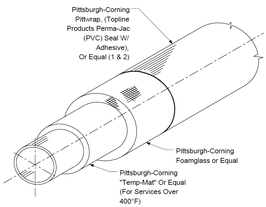
NOTES:
- Heat seal joints with torch or seal with approved manufacturer’s recommendations.
- Stainless steel bands shall be installed on nine–inch centers around outer jacket.
FIGURE 2
TRANSITION FROM ABOVE GROUND TO UNDERGROUND INSULATED LINES
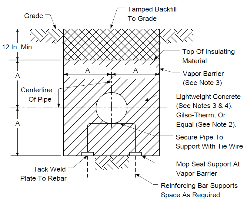
NOTES:
- When heat tracer is used without heat transfer cement, cover line with tracer tin secured at three–foot centers and at supports with tie wire before installing insulation
- When Gilso–Therm or equal is used, no vapor barrier is required.
- When lightweight concrete is used, install vapor barrier of mopped 30–pound felt on trench bottom and sides, allowing sufficient material for top lap. After concrete has set, fold over top and mop seal. Vapor barrier shall have 3–inch mopped laps at joints.
- Lightweight concrete specifications per yard shall be as follows: Three and one–half sacks of portland cement
Aggregate shall conform to ASTM C332.
The water/cement ratio and mixing procedures shall be per recommendations of the manufacturer of the lightweight aggregate.
- Dimension “A” to be specified on drawings.
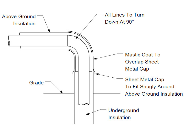
FIGURE 3
TRANSITION FROM ABOVE GROUND TO UNDERGROUND INSULATED LINES
© 2026 Inflection Point Engineering, LLC. All rights reserved. The content of this page — including calculation methods, reference data, written analysis, interactive tools, and source code — is the intellectual property of Inflection Point Engineering, LLC and is protected under applicable copyright, trademark, and trade secret laws. Unauthorized reproduction, redistribution, modification, or derivative use in whole or in part is prohibited without prior written consent.
Disclaimer. This material is provided for informational and educational purposes only and does not constitute professional engineering advice. Calculations, reference data, and methodologies are based on published standards and accepted engineering practice but are not a substitute for engineering judgment, site-specific analysis, or review by a licensed Professional Engineer. Inflection Point Engineering, LLC makes no warranties, express or implied, regarding the accuracy, completeness, or fitness for a particular purpose of any content presented here, and shall not be liable for any direct, indirect, incidental, or consequential damages arising from its use. Users assume all risk associated with applying this content to real-world design, operations, or decisions.
© 2026 Inflection Point Engineering, LLC. All rights reserved.