 Section 11 — Refractory, Insulation & Fireproofing
Fireproofing
IPE Engineering Practice IPE-EP-11-2-1
Document number: IPE-EP-11-2-1 · Section: 11 — Refractory, Insulation & Fireproofing
Figure 15 Fireproofing Clips 31Figure 15 Fireproofing Clips 31
Figure 16 Skirt Fireproofing 32Figure 16 Skirt Fireproofing 32
SCOPE
- The function of fire protection (fireproofing) required by this Practice is to provide heat insulating protection where deformation and possible failure as a result of exposure to a possible fire would seriously increase the magnitude of the fire, seriously endanger fire fighters, or seriously endanger personnel and property.
- This Practice covers the requirement of materials and methods for fire protecting structural steel, vessel skirts, equipment support lugs, equipment saddles, etc. The figures in the Practice provide details of fire protection.
- Whenever federal, state, or local ordinances exist, the more stringent requirements of this Practice or the ordinances shall be met.
- Any deviations from this Practice must be approved by the procedure described in EP 1–1–3.
- An asterisk (*) indicates that approval of the Owner’s Engineer is required or that additional information will be furnished by the purchaser.
- A revision bar indicates all changes made to this Revision.
2.0 REFERENCES
The latest edition of the following standards and publications are referred to herein.
STANDARDS AND PUBLICATIONS
| IPE Engineering Practices |
|---|
| EP 1–1–3 Deviations to IPE Engineering Practices Shop EP 10–3–1 Painting EP 11–2–2 Fire Protection Shields for Wafer Valves EP 11–3–2 Insulation Application - Piping EP 11–3–3 Insulation Application - Vessels and Equipment EP 11–3–6 Insulation of Flanged Joints and Valves in Hot Service |
| ACI |
| 506R Guide to Shotcrete |
| API Publications |
| Publ 2218 Fireproofing Practices in Petroleum and Petrochemical Processing Plants Publ 2510A Fire Protection Considerations for the Design and Operation of LPG Storage Facilities |
STANDARDS AND PUBLICATIONS (CONT.)
| ASTM |
|---|
| C33 Concrete Aggregates C94 Ready Mix Concrete C150 Portland Cement E84 Surface Burning Characteristics of Building Materials E119 Fire Tests of Building Construction and Materials E136 Behavior of Materials in Vertical Tube Furnace at 750C |
| ICBO |
| Uniform Building Code (UBC) |
| NFPA |
| 321 Basic Classification of Flammable and Combustible Liquids |
| UL |
| 1709 Rapid Rise Fire Tests of Protection Materials for Structural Steel |
DEFINITIONS
- Contractor - Company or business that agrees to furnish materials or perform specified services at a specified price and/or rate to the Owner.
- Fire Exposed Area - An area is considered fire exposed if it is horizontally within 30 ft. of any fire potential equipment or of the limits of a potential pool or stream of burning liquid, or if it is vertically within 40 ft. above any level at which a fire may be initiated. When a fire can be started above grade, the distance below (to grade) is also considered fire exposed.
- Fire Potential Equipment - Vessels, pumps, compressors, heat exchangers, fired heaters, and similar equipment containing such potential fire sources as flammable or combustible liquids or vapors, or both. Classification of flammable and combustible liquids shall be in accordance with NFPA 321.
- Inspector - A Inflection Point Engineering, LLC appointed engineer or inspector.
- Manufacturer - The recipient of a direct or indirect purchase order for materials and/or equipment. In this context, a direct order is one issued to a manufacturer by a contractor or the Owner. An indirect order is one issued to a manufacturer by a vendor (recipient of a direct order) for materials, fabricated components, or subassemblies.
- Non Fire Potential Equipment - Equipment that has little or no chance of releasing flammable or combustible fluids either before or shortly after the outbreak of a fire.
- Owner - Inflection Point Engineering, LLC.
- Owner’s Engineer - A Inflection Point Engineering, LLC appointed engineer.
- Purchaser - The party placing a direct purchase order. The purchaser is the Owner’s designated representative.
DOCUMENTATION
The following information shall be shown on drawings and included in job specifications:
- Items to be fireproofed and extent of fireproofing.
- Type and thickness of fireproofing material.
- Whether top coating of fireproofing is required, and specifications for same.
- Support dips required for fireproofing, furnished or to be installed.
- Materials and welding procedures, as applicable.
EXTENT OF FIRE PROTECTION
- Inside Battery Limits
- General
- Only columns, load bearing beams, and main bracing members require fire protection.
- Steel structure which only supports walkways and platforms does not require fireproofing.
- Do not fireproof the top flange of structural steel which supports process equipment, flooring, or piping.
- Fire protection shall comply with the guidelines of API Publication 2218.
- Equipment Supports
- Fire protect vessel SUPPORT LEGS; and vessel SKIRTS, inside and outside. Vessels <36 inch ID, require fireproofing on the outside of the skirt only. Use concrete on the skirts and legs of critical reactors and towers (fire hazardous). Proprietary material may be used on noncritical vessels.
- Fire protect STEEL LUGS supporting equipment except when the lug stress is less than 1500 psi AND they are more than 8 feet above grade.
- Fire protect STEEL SADDLES supporting horizontal vessels and exchangers when the minimum height, from the bottom of the drum (lowest point) to grade (or platform), is more than 18 inches.
- For stacked exchangers fireproof the bottom supports. The top supports require fire protection only when the top vessel is >30 inches diameter and the support members are higher than 12 inches at their lowest point. When more than (2) two exchangers are stacked, all intermediate supports shall also be fireproofed.
- Structural Steel & Pipe Racks
- Steel structures supporting vessels, exchangers, heaters or other fire potential equipment shall be fire protected from grade to the load line, generally not to exceed 100 feet above grade. If nonfire potential equipment is located at a higher level, the fire protection shall extend 40 feet above the level at which the fire potential equipment is supported (fire exposed area).
- For structures supporting nonfire potential equipment the structure shall be fireproofed from grade up to 40 feet.
- Use concrete or Owner Approved Proprietary materials on beams that support equipment.
- Steel structures supporting piping containing flammable material shall be fire protected from grade to the upper load line, generally not to exceed 40 feet. Fireproof columns and the beams supporting the piping (up to top flange). Use concrete or Owner Approved Proprietary materials. Pre–cast concrete may be used for pipe racks.
- Fire protection shall be provided on main pipe alley steel when the alley has fingers running in both directions.
Process Fingers
Main Pipe Alley
Process Fingers
- Where sections of a main pipe alley, as depicted in 5.1.3.c above, have long runs free of flanges and are not in a fire exposed area, fireproofing may be omitted. This shall be determined by Owner’s Engineer.
- (*)Generally, fireproofing shall not be provided on main pipe alley steel when the alley fingers run from only one side of the main pipe alley.
Main Pipe Alley
Process Fingers
- Where sections of a main pipe alley, as depicted in 5.1.3 (e), are within a fire exposed area, and/or the piping has a number of flanges, local fire protection is required.
- Piperacks which support equipment shall be considered the equipment support structure and fire protected.
- “Catch beams.” Where piping containing flammable materials is hung by rods or spring hangers from a fire protected member a “catch beam” shall be provided. The “catch beam” and its support beams shall be fireproofed. See Figure 2D, API 2218.
- REINFORCED CONCRETE structures shall be designed in accordance with the Uniform Building Code (latest edition), Chapter 43.
- (*)VESSELS specified to be completely fire protected, but not requiring insulation for process reasons, shall be done in accordance with paragraphs 5.1.7, 7.4 and 8.6. Consult Owner’s Engineer for fire protection of vessels/equipment made of low melting point materials (ex: aluminum) as special design recommendations are required.
- In general, PIPING in a fire exposed area is considered to be non fire potential equipment and is not required to be fireproofed. Piping specified to be completely fireproofed, but not requiring insulation, shall be fireproofed in accordance with paragraphs 5.1.8 and 5.1.9, and section 11.0 of EP 11–3–2.
- INSULATED VESSELS are considered fire protected when the insulating material thickness is equivalent to a fire endurance of 1 hour per UL 1709, or 2 hours per ASTM E119, when tested on a 10W49 column, and is jacketed with 304 stainless, 0.010 inch min. thickness, with stainless banding on 12 inch centers maximum. Flat vs. corrugated jacketing, and insulation materials, shall comply with the requirements in EP 11–3–3.
- INSULATED PIPING (up to NPS 24) is considered fire protected when insulated and jacketed as above, except with a fire endurance rating of 1 hour per UL 1709, or 2 hours per ASTM E119, when tested on a 4 inch steel column, .237 inch minimum wall, and a minimum weight of
10.79 pounds per foot. Jacketing and insulation materials shall comply with the requirements in EP 11–3–2. Lines larger than NPS 24 shall comply with the requirements for an insulated vessel.
- The insulation systems shall also meet the following requirements.
- Capable of withstanding direct flame impingement.
- Capable of withstanding the force of fire hose stream impingement.
- Is not destroyed when exposed to 1800F for 2 hours.
- Fired Heaters
- Integral stacks supported by the furnace structure shall have the structural members supporting the stack fire protected.
- Fire protect main heater columns from the top of concrete piers to within 2 inches of the underside of hearth plates.
- Fire protect supporting beams, legs, and cross pieces for fired heaters containing hydrocarbons. Horizontal support beams in contact with the fired heater floor do not require fireproofing, except at the junction point with a vertical column. Horizontal supports with a clearance of 12 inches or greater below the underside of the heater floor shall be fireproofed.
- Structural supports for elevated equipment associated with fired heaters, such as coke drums, transfer line exchangers, air preheaters, forced draft fans and ducts, shall be fireproofed if located within 20 feet horizontally of a fired heater handling flammable liquid in the tubes.
- EMERGENCY BLOCK VALVE OPERATORS shall be fire protected and comply with API 2218, Section 3.1.9.
- POWER AND CONTROL LINES (including cable trays), within fire exposed areas, or which are designated by the Owner’s Engineer as requiring fire protection because they are critical to emergency operations (see API 2218, section 3.1.8 for guidelines) shall be fireproofed. Fire protection shall comply with section 7.1 except that the fire rating shall meet 30 minutes per ASTM E119, or 15 minutes per UL 1709.
- (*)WAFER VALVES shall be fire protected when specified by Owner’s Engineer. When insulated, the design shall comply with EP 11–3–6. When insulation is not required, the valves shall be protected in accordance with EP 11–2–2.
- Outside Battery Limits
- Fire protection shall comply with the guidelines of API 2510A and API 2218.
- Equipment and pipe support structure up to 50 feet beyond battery limits and particularly pipe supports close to pipe flanges shall be fire protected.
- Steel support structures supporting fire potential equipment or subject to a flammable liquid spill fire shall be fire protected.
- Above ground pressure storage drums shall be protected as follows:
- If three or more drums are installed with a shell–to–shell spacing not exceeding 50 feet, each drum shall be fireproofed.
- If one or two drums are located with more than 50 feet spacing from other drums, provision for firewater protection of each drum is acceptable in lieu of fireproofing.
QUALITY
- The contractor shall be responsible that quality materials are used, and that all fire protection materials comply with section 7.0.
- For proprietary products, submit manufacturer’s literature to Owner’s Engineer. Submittal shall include complete application instructions for installation in accordance with supporting testing laboratory report to achieve the specified fire ratings, as well as the chemical and physical characteristics required.
- For proprietary products, submit certification that applicator has completed manufacturers approved training program and is certified by the manufacturer.
FIRE PROTECTION MATERIALS
- General
- Fire protection materials for non–carbon steel shall be free of chlorides of sulfates.
- Fire protection materials shall contain NO asbestos or toxic solvents.
- (*)Fire protection materials which have solvents with flash points below 100F (“red label”) shall not be used without approval of Owner’s Engineer.
- Fire protection materials for exterior use must comply with the following criteria:
- ASTM E119: 3 hour fire rating, with a minimum thickness for concrete/gunite of 2 inches, or UL 1709: 1–1/2 hour fire rating
- ASTM E136: Non–combustible
- ASTM E84: Flame spread: 0–20
- Fuel contribution: 0–5
- Smoke development: 0–50
- Quality control assurance FM or UL label on each unit
- ASTM E605: Minimum Density 45 pcf
- ASTM D–2240: Minimum Shore D of 40
- ASTM E761: Minimum Compressive Strength, 600 psi
- Use concrete or gunite encasement, subliming, intumescent, or other material which will provide the required fire endurance ratings and the durability and suitability for the intended use, as indicated by the quality criteria specified.
- Concrete
- Concrete shall meet the requirements of ASTM C94 for siliceous concrete as defined in section 4302(c) of UBC, and conforming to ASTM C33 and ASTM C150 type IA (type IIIA may be used with approval from Owner’s Engineer).
- Aggregate shall not exceed 1/2 inch nominal size.
- Concrete shall develop a minimum compressive strength of 3000 psi in 28 days.
- Concrete quality shall be per ASTM C94 alternate 2.
- Slump range shall be 3 to 6 inches.
- Owner Approved Proprietary Materials
- Fire protection materials selected for exterior use must maintain their degree of protection for 10 years when not exposed to fire.
- Demonstration of the materials’ fire performance is required before approval for use will be considered.
- Required maintenance of a system in order to meet the requirement in 7.3.1 must be specified in the bid. All maintenance schedules must be submitted to the Owner’s Engineer before approval for use is considered.
- Proprietary fireproofing materials approved for use by Inflection Point Engineering, LLC include: Carboline Pyrocrete 241 or PPG Pitt–Char. Use of alternate proprietary materials requires review and approval of the proposed material. Written approval must be obtained from the Owner’s Engineer before commencing work.
- Proprietary fireproofing materials approved for use by Inflection Point Engineering, LLC include: Carboline Pyrocrete 241 or PPG Pitt–Char. Use of alternate proprietary materials requires review and approval of the proposed material. Written approval must be obtained from the Owner’s Engineer before commencing work.
- Proprietary fireproofing materials shall comply with the requirements of paragraph 7.1.4.
- Special Vessel and Head Fireproofing
Vessel fire protection shall use Thermal Ceramics “Kaolite 20–S”, JM’s “Blazelite 2000”, or Inflection Point Engineering, LLC approved alternate. These shall be appropriately weatherproofed and have a minimum of 2 inch thickness.
- Primers, Topcoats, and Caulking
- Prime ALL steel prior to fireproofing, but after the application of any studs. For special coatings over galvanized steel, stainless steel and aluminum, consult fireproofing manufacturer for recommendations. Prime steel under concrete fireproofing with an epoxy mastic, Carboline’s Carbo–Mastic 15, Valspar 75W9W, or equivalent.
- Apply primers, topcoat, and caulking as required by manufacturers’ printed instructions.
- Confirm that the primer and topcoat are compatible with the fireproofing.
- For caulking concrete or gunite, use Porter International GPA032, flexible thiokol expansion joint compound or approved equal.
- Fireproofing mastic shall be a breather type, asbestos free, with a flame spread of 4 or less (Vimasco WC - IFR).
- Reinforcing Materials
- Reinforcing materials such as metal lath, fiberglass, anchoring studs, or other products used in the fire protection system shall be of the weight, size, and type specified in the fire rating design.
- Reinforcing for concrete or gunite:
- Wire Mesh - 2x2x.083 (#14 BWG) inches galvanized welded wire fabric. For vessel shells and heads, see paragraph 8.6.3.
- Tie wires #18 BWG galvanized steel wire
- Studs - Galvanized, primed metal, or an approved corrosion resistant material. Studs shall be attached by electric stud welding or hand welding. All studs shall be tested for satisfactory base welds by being hammer tested.
- Reinforcing for mastic coatings shall be wire mesh, 1 inch hexagonal woven wire poultry mesh,
.035 inch (20 BWG) minimum wire diameter. Wire shall be stainless steel. The mesh shall be laced into place with .08 inch (minimum) diameter wire of the same material.
- Water
- Water shall be clean, potable, and free from excess contaminates. Firewater is NOT
acceptable.
INSTALLATION OF FIRE PROTECTION MATERIALS
- Surface Preparation
- All steel to be fireproofed shall be thoroughly cleaned of scaling paint and rust, loose concrete, soot, grease, and other materials which could impair the bond between the encased member, vessel shell, head, or skirt and the fireproofing BEFORE the reinforcement is placed.
- All steel and equipment SHALL be primed after cleaning and prior to fireproofing. Surface preparation shall comply with EP 10–3–1 and product manufacturer’s recommendations. If studs/standoffs are welded to the steel, sandblast and prime the steel after welding. The primer will be repaired where welding breaks the paint. In areas of high corrosion, as specified by Owner’s Engineer, sand blast and apply a corrosion resistant paint.
- For Owner approved proprietary fireproofing materials, surface preparation shall be performed in accordance with the manufacturer’s recommendation.
- Installation: General
- Wire fabric shall be carefully bent to fit around corners and in re–entrant angles.
- For concrete the fabric shall be placed about 3/4 inch from the final surface of the gunite.
- Lap mesh a minimum of 3 inches at joints. Tie mesh with wire on 6 inch centers.
- Fire protection materials shall not be applied when the ambient temperature is below 40 F, or below the manufacturers recommended temperature, whichever is higher.
- Protect finished surfaces and adjacent equipment (metal switch boxes, conduits, etc.) by masking or covering against overspray and spillage.
- Install fire protection materials after all steel is in place. Other trades shall be restricted from working on, or adjacent to, freshly applied material for at least 24 hours, or as per manufacturer’s recommendations, after completing application.
- When saddles, spacers, or supports that have slotted holes, or other type connections which permit thermal movement, are to be fireproofed, special fire protection details that allow for movement without damaging the fireproofing shall be shown on the drawing.
- A trowelled finish shall not be applied. Trowelling shall only be used for dimensional reasons (cutback).
- All exposed joints (exposed steel and fireproofing intersections) shall be caulked with a silicone (elastic) caulking compound. Slope fireproofing downward from intersection to facilitate drainage.
- Cementitious materials (gunite) application shall comply with ACI 506R. Materials may be applied in a single thickness (preferred) or built up in layers, depending on the position of work. The thickness of a layer is dependent upon the requirement that the material not slump. If overhead or vertical surfaces are gunited in layers, a minimum of three layers is recommended. Time between coats shall be 39 minutes to 4 hours depending upon the temperature and humidity. The surfaces should be allowed to stiffen slightly, but not allowed to set.
- All fireproofing located outdoors shall be effectively sealed to prevent moisture from reaching the fireproofed steel surface.
- All Owner approved proprietary fireproofing materials shall be installed in accordance with the manufacturer’s recommendations.
- Concrete Application
- When concrete is specified it shall be mixed, applied and cured in accordance with the latest American Concrete Institute Code.
- Concrete temperatures shall be maintained between 50 and 100F during placement and curing (see paragraph 8.3.5 for curing time).
- Sandstone, silica gravel or other siliceous material shall be used as the coarse aggregate in fireproofing concrete.
- Vibration of forms shall be done to minimize voids when poured in place (formed) fireproofing is used. Vibration shall be applied to the outside of the form.
- Keep concrete damp for seven days after placement.
- Structural Steel & Vessel Support Legs
- Concrete fire protection on structural steel shall be applied by approved formed-concrete, boxed–on, or contour-formed methods, as per Figure 1 through Figure 12.
- Owner approved fireproofing materials shall be applied following the manufacturer’s recommendations.
- Wrap lath around columns or beams in accordance with UL designs.
- Structural members smaller than 12 inches shall use a boxed or poured in place design. On structural members 12 inches and larger use a contour or poured in place design.
- When a box configuration is used, install firestops at 8-foot centers (max.) in boxed columns. Firestops shall consist of lath being bent into the web and material gunned on top of it.
- In columns, the box beam will only go up to within 12 inches of the top. At this point the lath is sloped into the web and the final 12 inches will be contour design. See Figure 7 for details. Chamfer and caulk the top edge of the contoured material.
- Where the fire protection does not extend the full length of a vertical beam, the top edge shall be chamfered and caulked prior to installation of flashing. Fire protection material that extends to the top of a vertical beam shall be covered with a seal plate. See Figure 11 for details.
- Vessel support legs shall be fire proofed per Figure 13 and Figure 14, except that for pressurized storage spheres the fireproofing shall not cover the supports where they are welded to the shell.
- Where fire protected columns are exposed to abuse (i.e., truck and heavy equipment movement) steel barriers shall be provided.
- Vessel Skirt
- The concrete, equipment, and method of application shall be in accordance with “Recommended Practice for Shotcreting” ACI 506R.
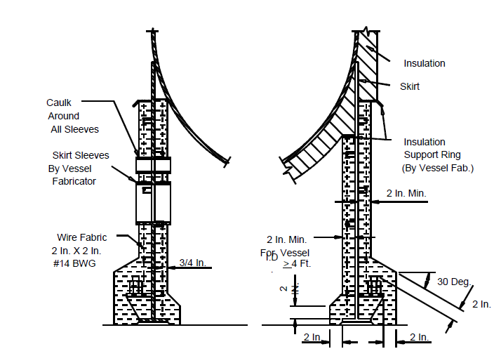
- Fireproofing on skirts shall be pneumatically applied. Flashing and reinforcement shall be in accordance with Figure 15 and Figure 16.
- Studs shall be spaced in a diamond pattern on 16-inch centers (max.). Studs will be welded on the skirt by the vessel fabricator prior to shipment.
- Owner approved fireproofing materials shall be applied following the manufacturer’s recommendations.
- Sealing and caulking materials shall be employed at vents, access and pipe openings to prevent water from seeping between the fireproofing and skirt at these locations.
- Vessel Shell and Heads
- Special fire protection materials shall be used when shell and heads are to be fireproofed, but do not require insulation.
- Manufacturers’ recommendations shall be followed to prepare and apply material.
- Reinforcement for cementitious fire protection material shall be 2x2x0.109 (#12 BWG) inches, galvanized welded wire fabric. The fabric shall be fastened in place about 1–1/4 inch from the vessel surface. It shall be securely anchored to fasteners welded to the vessel surface on 16x16 inch centers.
- Anchors of 3/8-inch diameter rods in the form of rings to pass over nozzles and manhole necks shall be provided for anchoring the wire fabric at these points.
- The fire protection material, as applied, shall be allowed to dry for a minimum length of time recommended by the manufacturer. In the case of Thermal Ceramics “Kaolite 20–S” this period is one week.
- After the fire protection material has been allowed to dry as prescribed by the manufacturer, a weatherproofing topcoat shall be applied over the external surface. The weatherproofing shall comply with manufacturer’s recommendations. If a fireproofing mastic is used it shall be reinforced with wire mesh and shall be 1/8 inch thick (dry film) minimum.
INSPECTION
- Fireproofing shall be inspected by the Owner’s inspector during the initial installation of each type/design of fireproofing to ensure compliance with this Practice, applicable ACI codes, and/or the manufacturer’s installation instructions. Written approval of the actual field installation, and installation procedures, shall be obtained by the contractor from the Owner’s inspector before proceeding with additional work.
- No more than 5% of the fireproofing may be installed prior to obtaining the inspector’s approval, unless otherwise approved by Owner.
- The surface preparation and priming/coating of all steel shall be inspected by a NACE certified inspector prior to the application of any fireproofing.
- Acceptance for thickness will be based on random measurements of the lining. Exposed mesh reinforcement is not acceptable. It is important that the measurements correspond to the dry material thickness.
- Materials and workmanship not in accordance with this Practice, the approved installation procedures, any drawings, and contract documents shall be corrected at the expense of the contractor.
- All anchors shall be inspected to ensure they are the correct material, height, and spaced properly. Hammer test studs to insure they are welded correctly. A minimum of 5% of the studs shall be checked.
10.0 TABLES
TABLE 1 DOCUMENTATION REQUIREMENTS FOR FIREPROOFING PER EP 11–2–1
| Item | Description | Format | As–Built |
|---|---|---|---|
| 1 | Items to be fireproofed and extent of fireproofing. | See EP 2-5-2 | Yes |
| 2 | Type and thickness of fireproofing material. | See EP 2-5-2 | Yes |
| 3 | Whether top coating of fireproofing is required, and specifications for the same. | See EP 2-5-2 | Yes |
| 4 | Support clips required for fireproofing, furnished or to be installed. | See EP 2-5-2 | Yes |
| 5 | Materials and welding procedures, as applicable. | See EP 2-5-2 | Yes |
11.0 FIGURES
FIGURE 1
BEAMS OR COLUMNS SMALLER THAN 12 INCHES
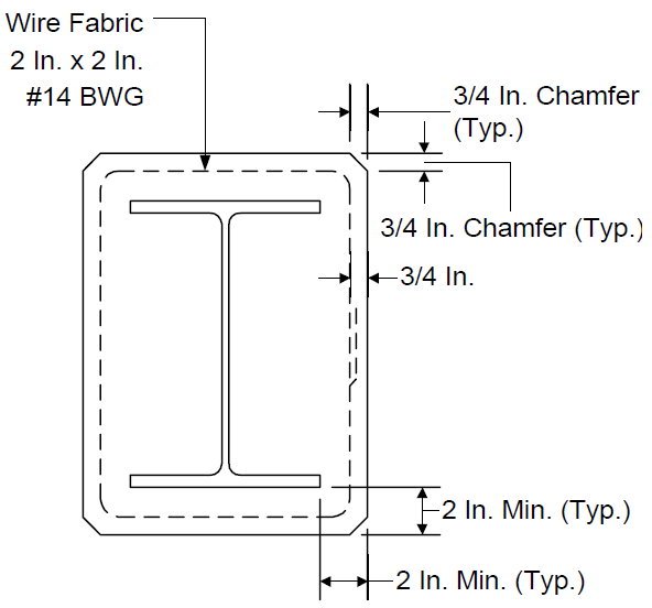
FIGURE 2
PIPE SUPPORT BEAMS SMALLER THAN 12 INCHES
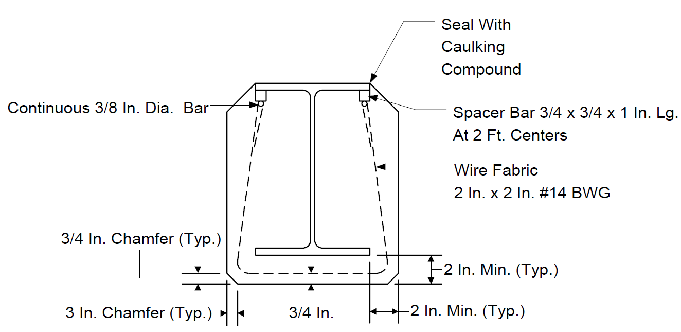
FIGURE 3A
BEAMS OR COLUMNS 12 INCHES OR GREATER
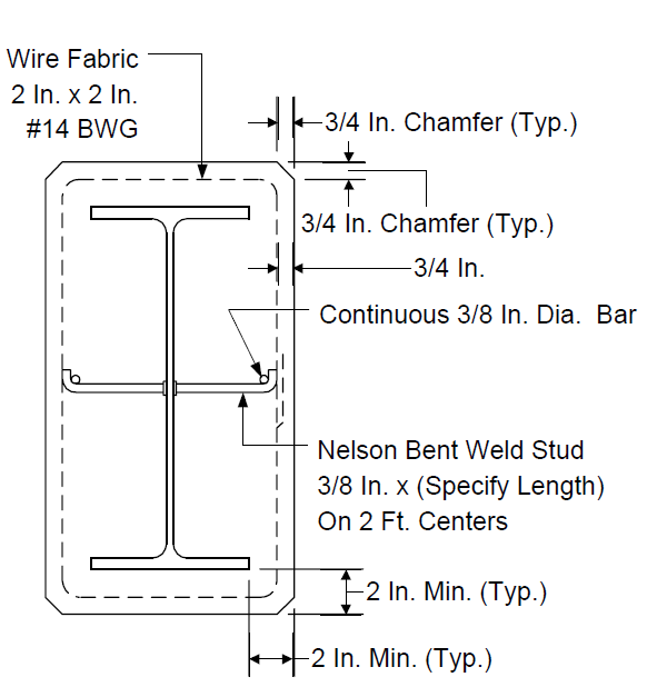
FIGURE 3B
BEAMS OR COLUMNS 12 INCHES OR GREATER
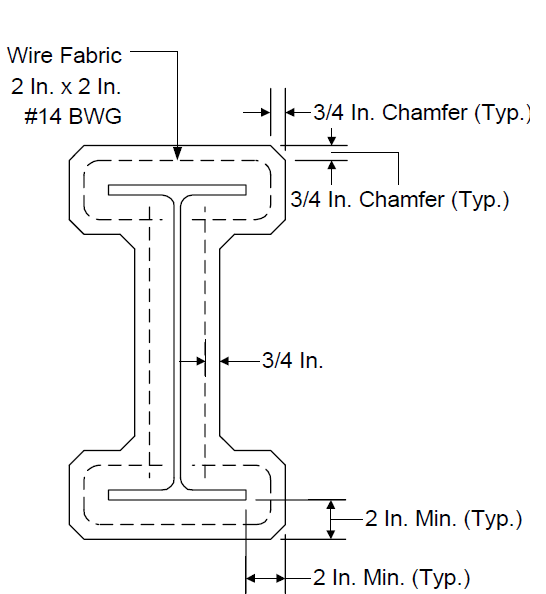
FIGURE 4 CHANNELS
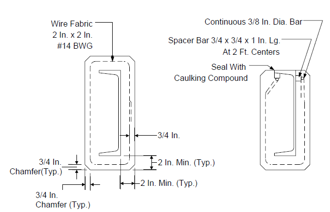
FIGURE 5
TWO ANGLES BACK TO BACK OR TEE
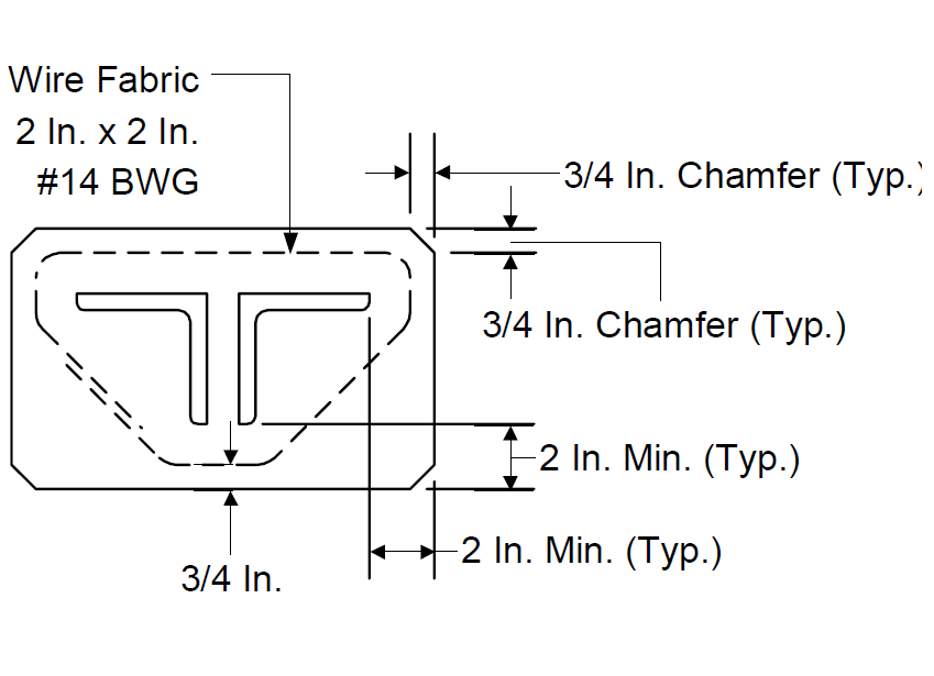
FIGURE 6 ANGLES
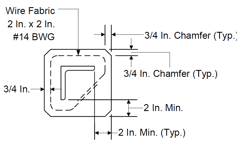
FIGURE 7
“BOXED” TO “CONTOURED” TRANSITION ON COLUMNS
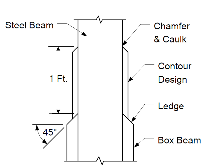
FIGURE 8
BEAMS SMALLER THAN 12 INCHES - AT PLATFORMS
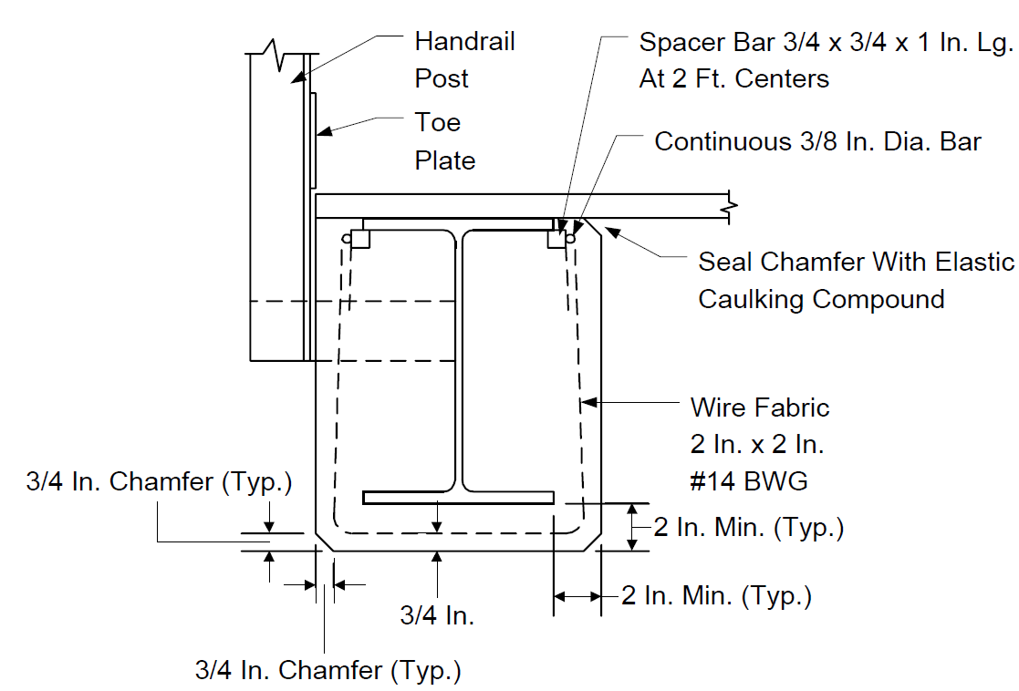
FIGURE 9 CHANNELS AT PLATFORMS
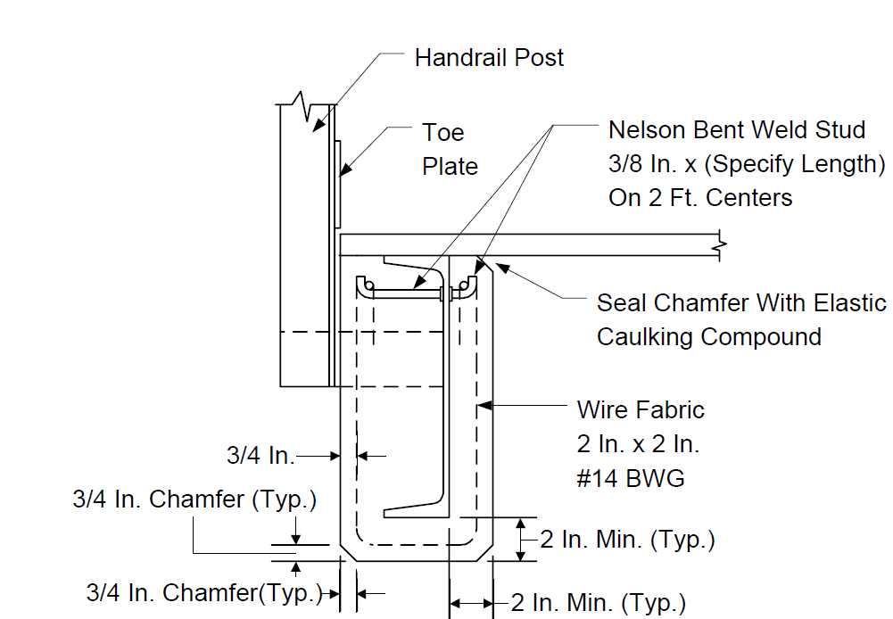
FIGURE 10A
BEAMS SMALLER THAN 12 INCHES - AT PLATFORMS
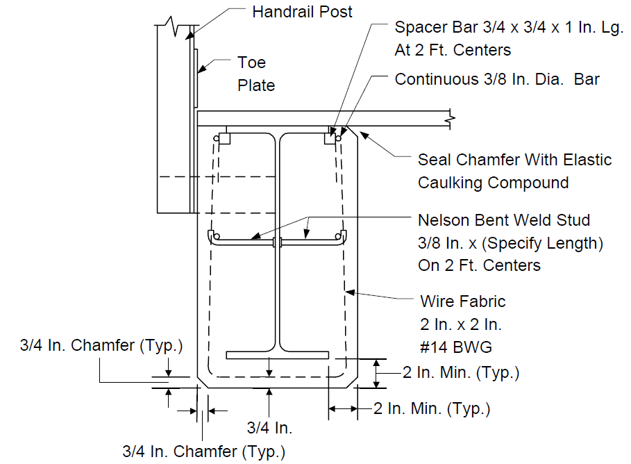
FIGURE 10B
BEAMS 12 INCHES AND LARGER - AT PLATFORMS
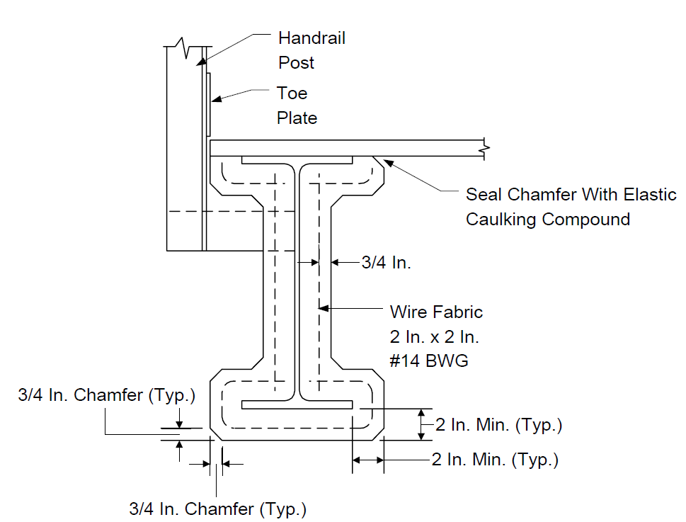
FIGURE 11
TYPICAL METHOD OF FLASHING COLUMN AT TOP OF FIREPROOFING
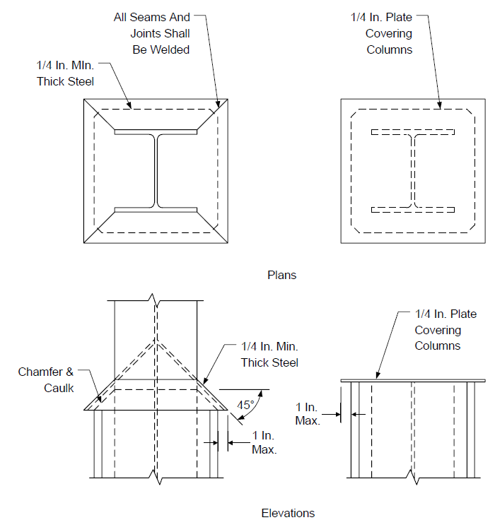
FIGURE 12
ACCEPTABLE METHODS OF SUPPORTING WIRE FABRIC AT CORNERS
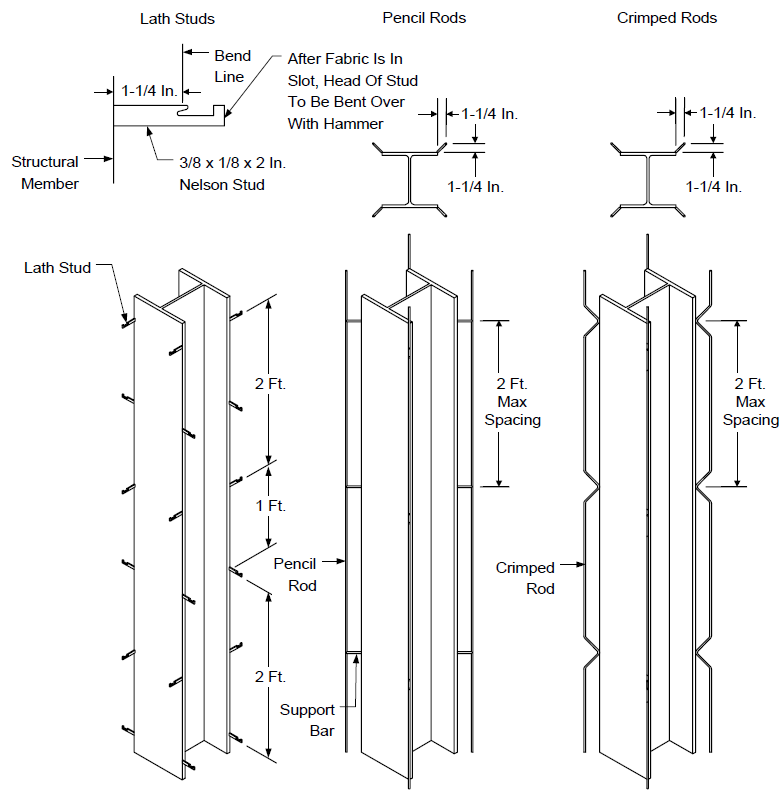
FIGURE 13 SUPPORT LEG FIREPROOFING
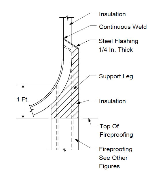
FIGURE 14 SUPPORT LEG FIREPROOFING
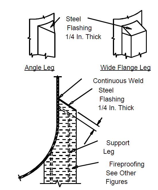
FIGURE 15 FIREPROOFING CLIPS
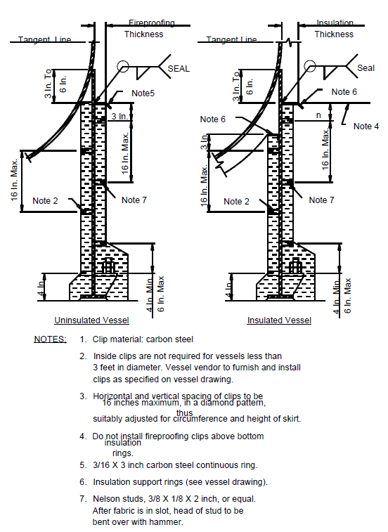
FIGURE 16 SKIRT FIREPROOFING
© 2026 Inflection Point Engineering, LLC. All rights reserved. The content of this page — including calculation methods, reference data, written analysis, interactive tools, and source code — is the intellectual property of Inflection Point Engineering, LLC and is protected under applicable copyright, trademark, and trade secret laws. Unauthorized reproduction, redistribution, modification, or derivative use in whole or in part is prohibited without prior written consent.
Disclaimer. This material is provided for informational and educational purposes only and does not constitute professional engineering advice. Calculations, reference data, and methodologies are based on published standards and accepted engineering practice but are not a substitute for engineering judgment, site-specific analysis, or review by a licensed Professional Engineer. Inflection Point Engineering, LLC makes no warranties, express or implied, regarding the accuracy, completeness, or fitness for a particular purpose of any content presented here, and shall not be liable for any direct, indirect, incidental, or consequential damages arising from its use. Users assume all risk associated with applying this content to real-world design, operations, or decisions.
© 2026 Inflection Point Engineering, LLC. All rights reserved.