 Section 11 — Refractory, Insulation & Fireproofing
Fired Heater Refractory
IPE Engineering Practice IPE-EP-11-1-2
Document number: IPE-EP-11-1-2 · Section: 11 — Refractory, Insulation & Fireproofing
Table 6 Documentation Requirements For Fired Heater Refractory 25Table 6 Documentation Requirements For Fired Heater Refractory 25
22.0 FIGURES 26
Figure 1 Nose Detail 26Figure 1 Nose Detail 26
Figure 2 Access Door 26Figure 2 Access Door 26
Figure 3A Studs For “Single Layer” Lining 27Figure 3A Studs For “Single Layer” Lining 27
Figure 3B “Single Layer” Linings 28Figure 3B “Single Layer” Linings 28
Figure 3C Studs And Anchors For Dual Layer Lining 29Figure 3C Studs And Anchors For Dual Layer Lining 29
Figure 4 Anchor Patterns For Castables 30Figure 4 Anchor Patterns For Castables 30
Figure 5 Wire Mesh Anchor Spacing For Stacks And Round Ducts 31Figure 5 Wire Mesh Anchor Spacing For Stacks And Round Ducts 31
Figure 6 Anchor Tie Back For Brick Lining 32Figure 6 Anchor Tie Back For Brick Lining 32
Figure 7A & B Anchor Pattern And Spacing For Compression & Lap Joints of
Ceramic Fiber Blanket 33Ceramic Fiber Blanket 33
Figure 8 Observation Door Detail 34Figure 8 Observation Door Detail 34
Figure 9 Typical Panel Joint 34Figure 9 Typical Panel Joint 34
Figure 10 Repair of Castable Linings 35Figure 10 Repair of Castable Linings 35
SCOPE
- This Practice governs the general requirements for the application and design of all shop and field installations of internal insulating and refractory linings for fired heaters, breaching, ducting and stacks.
- The contractor may quote alternates to this Practice; however, all variances must be clearly indicated at the time of proposal.
- ANY deviations from this Practice must be approved by the procedure described in EP 1–1–3.
- IPE requires 5 days notice before any phase of refractory installation can begin.
- An asterisk (*) indicates that a decision by the Owner or Owner’s Engineer is required or that additional information is furnished by the purchaser.
- This Practice is appropriate for attachment to an inquiry or purchase document when accompanied by the referenced IPE Engineering Practices and the completed data sheets.
- A revision bar indicates all changes made to this Revision.
2.0 REFERENCES
The latest edition of the following publications are referred to herein.
STANDARDS AND PUBLICATIONS
| IPE Engineering Practices |
|---|
| EP 1–1–3 Deviations to IPE Engineering Practices EP 11–1–1 Internal Insulating and Refractory Lining EP 11–1–2 DS Fired Heater Refractory Data Sheet EP 11–1–2C Fired Heater Refractory Inspection Checklist |
| ASTM Standards |
| C27 Fireclay and High Alumina Refractory Brick C113 Reheat Change of Refractory Brick C133 Cold Crush Strength and Modulus of Rupture Refractory Bricks and Shapes C155 Classification for Insulating Firebrick C201 Thermal Conductivity of Refractories C612 Mineral Fiber Block and Board Insulation C860 Practices for Determining Consistency in Refractory Concrete C892 High Temperature Fiber Blanket Thermal Insulation |
| SSPC Standards |
| SP6 Commercial Blast Cleaning |
3.0
3.1
3.2
3.3
3.4
3.5
3.6
3.7
3.8
4.0
5.0
5.1
5.2
6.0
6.1
6.2
6.3
DEFINITIONS
IFB - Insulating Fire Brick
Inspector - A Inflection Point Engineering, LLC appointed engineer or inspector. Owner - Inflection Point Engineering, LLC
Owner’s Engineer - A Inflection Point Engineering, LLC appointed engineer.
Refractory Class: Light Weight - materials having an installed fired density of 75 pcf or less.
Refractory Class: Medium Weight - materials having an installed fired density greater than 75 pcf and less than, or equal to, 120 pcf.
Refractory Class: Heavy Weight - materials having an installed fired density greater than 120 pcf and less than, or equal to, 150 pcf.
Refractory Class: Dense - materials having an installed fired density greater than 150 pcf.
JOB SPECIFICATIONS
IPE shall issue specific requirements for refractory lining of a particular piece of equipment. This shall include type of refractory system, thickness, materials, method of refractory support and process conditions. For repair or replacement of refractory the job specification shall define the extent of refractory removal, cleaning, etc. which is required. Plant safety rules will be included as necessary.
CONTRACTOR SPECIFICATION
(*)The lining contractor is expected to install refractory in strict accord with manufacturers’ recommendations and the more general requirements of this practice. Conflicts will be resolved
by Owner’s Engineer.
Prior to application, the lining contractor must prepare a written supplemental specification and obtain approval of both the Owner’s Engineer and refractory supplier. The supplemental specifications must cover the installer’s application procedures and include specific requirements for mixing, applying, curing, etc.
DOCUMENTATION
All material properties shall be tested to ASTM Standards. Any deviations shall be reported to Owner’s Engineer.
Manufacturer’s data sheets showing gunned physical properties shall be supplied for all products to be pneumatically applied.
Bid Stage : The following information shall be supplied at the bid stage to assure complete evaluation:
- Requirements as specified in the Owner’s data sheets included in EP 11–1–2 DS.
- Brick: The following are in addition to the data sheets:
- Design of expansion joints.
- Description of mortar to be used.
- Ceramic Fiber Insulation : The following are in addition to the data sheets:
- Linear change at maximum service and operating temperatures.
- Installation details and blanket joint details.
- Final Design Approval Stage: The following information shall be supplied for approval by Owner’s Engineer for all final lining designs (i.e. after the order is placed).
- Owner’s Data Sheet requirements in EP 11–1–2 DS.
- Any changes from proposal information.
- Brick: Resubmit the items in 6.3.2 above.
- Ceramic Fiber Insulation : Resubmit the items in 6.3.3 above.
- Name and telephone number of reference contacts at plants for whom the refractory installer, within the past 2 (two) years, has applied the type of refractory covered by this project.
- Shipping and handling procedures for all refractory lined equipment or components shall be submitted for approval by Owner’s Engineer. Sufficient detail, including shipping supports, shall be provided to show that the parts will not be damaged by the usual handling and weather to be expected in transit and at the erection site.
- Final Records: per Owner’s Data Sheets included in EP 11–1–2 DS.
DESIGN
- Heater casing, including breechings, hot flue gas, and air ducts, shall be designed so the temperature of the exterior surface does not exceed 180°F when the ambient air temperature is 80°F in still air. For the design of repairs to existing equipment, the shell temperature may be extended to the design metal temperature with approval of the Owner’s Engineer.
- The heater floor refractory shall have a 5 inch minimum thickness. The floor facing, the top 2 inches, shall be heavy weight material (min).
- Convection side wall/nose detail shall be selected to prevent the convection wall load from bearing on the nose, and to adequately support the nose, see Figure 1.
- Ceramic fiber packing shall be attached along the edge of all compartment doors for air tightness.
- A light weight insulating lining, ceramic fiber, or block insulation, 2 inches thick (min), shall be provided for the sides, top and doors of header boxes and for access doors. Ceramic Fiber may be used for repairs only.
- The refractory and insulating material of any layer shall be suitable for a service temperature at least 400°F (500°F for ceramic fiber) above its calculated hot face temperature. Minimum service temperature for refractories at the hot face shall be 2000°F in the radiant and shield sections. L–H–V REFRACTORY IS NOT PERMITTED.
- Burner blocks shall have a minimum service temperature of 3000°F, and shall be prefired prior to shipment to the plant.
- For stacks, a metal cap, 18 Cr 8 Ni stainless steel, 1/8 inch minimum thickness shall be 100% seal welded at the top to protect the horizontal surface of the refractory from the weather.
- When the fuel fired contains more than 400 ppm vanadium plus sodium, the following shall apply:
- “Facing” to be only Dense–type castable
- Overall Al2O3 content 40% min., with not less than 40% Al2O3 in aggregate
- SiO2 content 35% max
- When the fuel fired contains w 0.5% (mass) sulfur, the following applies:
- A protective coating to prevent acid corrosion is to be applied to the casing (see Section 9.0 for acceptable coatings).
- When ceramic fiber is used, a stainless steel vapor barrier shall be used. (see Section 13.0)
- Castable materials shall have a total concentration of free alkali, MgO, and iron in the aggregate of less than 15%.
- The “facing” of a castable or brick lining shall be “medium weight” or heavier.
- Areas lined with plastic refractory or chemically bonded refractories shall comply with the requirements, as applicable, in EP 11–1–1.
- See Figure 2 for typical access door details.
- Expansion joints shall be provided around burner blocks and prefired shapes.
ANCHORS
- General
- Selection of materials for anchoring components shall be based on the maximum design temperature as defined in paragraph 7.6 and corrosion resistance of the material shown in Table 1.
- Anchor temperature calculations shall be provided for all operating and regenerating conditions.
- Austenitic, Inconel, and RA330 materials shall be supplied and installed in the fully bright solution annealed condition. Anchors shall be clean and free of oxidation coatings. Anchors shall not be formed after annealing. Bending of anchors, after welding, for height adjustment is not allowed without approval of Owner’s Engineer. See paragraph19.1.5 for material test requirements.
- All anchors shall be completely free from dirt, grease, oil, or other deleterious materials.
- Vee and Longhorn Anchors
- Acceptable anchors for single and multi–layer castable linings are shown in Figures 3 (A–C). Anchor pattern is shown in Figure 4, except for stacks where wire fabric may be used for reinforcing when the provisions of Section 8 are met. (See Figure 5).
- Anchor heights shall not be closer than 1/2 inch to the hot face.
- When anchor tip coatings are specified, the tips of all anchors shall be coated with mastic or plastic that will burn off during dryout and provide allowance for anchor expansion during unit operation. The coating shall extend from the tip of the anchor to past the first bend (1 inch maximum).
- The measurements shown in Table 2 shall be the maximum anchor spacing based on the full thickness of the lining.
- Wire Mesh
- 2–1/2 inch linings where gas temperatures are below 400°F, in stacks or round ducts, may be supported on either alloy anchors or stainless steel wire fabric 2 inch x 2 inch, 1/8 inch diam. All linings over 2–1/2 inches in total lining thickness, and all linings on flat surfaces, shall be supported by anchors.
- The wire fabric shall be placed so that the distance between the hot face and the wire fabric is approximately 1 inch. Maximum anchor spacings, longitudinal SL and circumferential Sc , for wire fabric are shown in Figure 5.
- Brick Anchors
- A typical tie back anchor for I.F.B’s is shown in Figure 6.
- All supporting shelves and tie members shall be austenitic chrome–nickel alloy material, except that pipe–type supports located in the insulating block may be carbon steel, providing the metal temperature does not exceed 500°F Metal support shelves (lintels) shall be attached to the casing on vertical centers not to exceed 6 feet. The support shelves shall be slotted to provide for differential thermal expansion.
- For suspended arches, no more than two bricks shall be carried by each support.
- Ceramic Fiber Anchors
- Metal anchors and retainer washers shall be used unless otherwise specified by Owner.
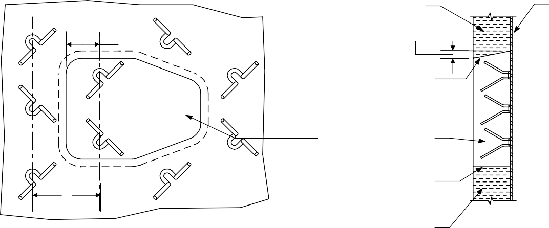
- (*)Typical anchor pattern and spacing are given in Figures 7(A & B). Anchor patterns shall be reviewed and approved by Owner’s Engineer.
- When the installation has been completed, the metal stud and washer projecting through the hot face shall be covered with a wrapped piece of blanket, or ceramic fiber moldable, for protection.
- (*)The anchor assembly for ceramic fiber modules shall be reviewed and approved by Owner’s Engineer. Anchor assemblies for modules shall be located a maximum distance of 2 inches from the module cold face. Arch modules shall have (2) two anchors per module.
- Ceramic Anchors
- Ceramic anchors shall be handled with care to avoid cracking or chipping.
- Care shall be taken when using ceramic anchors in high traffic areas to minimize damage/ breakage to the anchor. These anchors can be easily damaged.
- Ceramic pins for fiber blanket installations shall comply with paragraph 8.5.2 of this Practice. Spacing and clearance for ceramic pins are the same as for metal pins.
- Installation
- Attachment of anchors shall be by welding, either stud–gun or manual. For stud–gun applications, surfaces SHALL be ground to clean metal. If by manual welding, welds shall be continuous and completely encircle the anchor. Chip all slag from welds. See Section 19.0 for test requirements. See Section 9.0 for surface preparation requirements.
- The weld on an anchor foot shall stop 1/4 inch from the bend of the anchor leg.
- Maximum anchor distance from an edge or discontinuity shall be 3 inches, except for ceramic anchors. Ceramic anchor clearance from an edge or discontinuity shall be 6 inches (maximum).
- When laying out anchor locations do not use a waxed crayon as this may cause poor contact between the anchor and casing.
SURFACE PREPARATION
- All surfaces to which refractory is to be applied either metal or refractory (including anchors) shall be cleaned and made free of loose particles or materials deleterious to the refractory. Clean painted or unpainted metal surfaces free of loose rust, dirt, grease or oil are acceptable metal surfaces for most linings covered under this specification.
- (*)All surfaces to which a shell coating is to be applied, for corrosion protection, shall be sandblasted to a standard commercial finish (SSPC–SP6). If the casing is allowed to sit, and rust forms, then the surfaces shall be resandblasted.
- Acceptable shell coatings: coal tar epoxy stalastic or Carboline 1248. Sodium silicate shall not be used. Shell coatings shall be applied in accordance with manufacturer’s recommendations after anchors are welded. Shell coatings shall withstand a temperature 50°F above the calculated temperature of the shell.
- Sandblasting of surfaces which do not require a shell coating shall be governed by the following guidelines:
- Components that have previously been in operation shall be sandblasted prior to the welding of anchors and other metallic components.
- (*)New components shall be dry sandblasted after welding of anchors and other metallic components, except at the inspectors discretion, and approval of the Owner’s Engineer, sandblasting may be omitted in which case the purchaser shall receive a price deduct. Areas to which anchors are to be welded shall be spot cleaned prior to welding.
- When required, sandblast to a standard commercial finish (SSPC–SP6) to remove all paint, rust, loose mill scale or other foreign material. The point of welding anchors must be completely clean metal.
- If sandblasting is not required, or a tight scale remains on the casing after sandblasting, the areas to which metal components/anchors are to be welded shall be ground to clean metal prior to welding.
- After sandblasting, the interior of the unit shall be cleaned. Do not wash with water.
- Before commencing any section of work, an adequate area of surface and work area must be cleaned and prepared to ensure that the work can proceed in an orderly and workmanlike manner without danger of incorporating dirt, debris, or dehydrated materials in the work.
- Refractory placed over or against improperly cleaned surfaces will be rejected. The inspector shall verify cleanliness prior to the start of installation.
- Supporting members, pipe sleeves or exposed structural items, within the limits of an installed lining, shall be wrapped with 1/2 inch (min) ceramic fiber paper, ceramic fiber blanket, or coated with 1/8 inch elastic to allow for expansion without damage to the lining.
REFRACTORY HANDLING AND SHIPMENT
- Shipment of hydraulic setting refractories shall be scheduled to insure that the age of the binder cement is less than 3 months old at time of shipment and less than 6 months old at time of refractory installation. Any material over 6 months old may be rejected by Owner.
- Each bag or box of refractory shall be identified by the code date of the manufacturer. Each pallet shall be numbered in a minimum of three locations on the pallet to assure batch identification. When products are manufactured specifically for a project, the pallets shall be numbered sequentially and in the order of manufacture.
- For field or shop linings, protection from moisture shall be provided during shipping, handling, and storage. Material longest in storage shall be used first.
- For shop lined panels, panels shall be packaged to minimize abrasion to the lining surface during shipment.
- Any opened or damaged refractory shall be discarded. All refractory exceeding its shelf life shall be discarded.
- The equipment fabricator shall be responsible for protecting, during shipment, equipment with refractory installed prior to arrival at the job site. Repair of a lining damaged during shipment is the responsibility of the equipment fabricator.
BLOCK INSULATION
- Block insulation shall comply with ASTM C612, Type 5.
- Mastic adhesive or refractory mortars shall be used to secure all block. Mastic shall be applied so as the block is not held off the shell leaving an air space between block and shell.
- (*)Block insulation thickness 3 inches and over shall not be used without approval of Owner’s Engineer. Detailed analysis of support system, expansion, and contraction of the system will be required.
- Block insulation used in floors or lower duct surfaces, which could be walked on, shall have a minimum compressive strength of 30 psi.
- Block insulation shall be installed over anchors which do not tear or crack the block. Rigid block shall be wired in place with 14 USS gauge, stainless wire. Two part anchors, such as Figure 3C, are preferred.
- All joints must be square, butt, and tight.
- Block insulation shall not be used when fuel sulfur content exceeds 1%.
BRICK LININGS
- All brick linings on vertical flat casing shall be tied back to and supported by the structural steel framing members. A minimum of 20% of the bricks shall be tied back.
- Brick and tile arches shall be of suspended construction. For vertical cylindrical heaters, each refractory shape shall be individually supported by an austenitic chrome–nickel support member.
- Floor brick shall not be mortared. The floor face brick shall be high–duty fireclay brick (min.) and comply with paragraph 7.2 of this Practice. A 1/2 inch expansion joint shall be provided on 6 foot centers and shall be covered with dense brick to prevent entry of debris.
- All joints shall be staggered and shall be set with fireclay or air setting mortar, and expansion joints shall be provided at a maximum spacing of 12 feet in both directions. For hot face design temperatures over 2000°F, a dry joint shall be provided between each expansion joint.
- Insulating firebrick shall have flat, uniform surfaces on all faces which have been ground or cut to size within a tolerance of plus or minus 1/16 inch for all dimensions.
- Minimum temperature ratings for hot face brick shall be 2600°F on walls with mild flame impingement and 2300°F for other exposed or shielded wall applications.
- Maximum shrinkage at hot face temperature shall be 0.1 percent.
- Curing procedures are not required provided brick has remained dry.
- Refractory tile and brick shall conform to ASTM C27. Insulating firebrick shall conform to ASTM C155, Group 23.
CERAMIC FIBER LININGS
- Ceramic fiber blanket refractory shall conform to 45–52% Al2 O3; 46–53% SiO3.
- Minimum lining service temperature for the firebox hot face layer shall be 2300°F.
- (*)The hot face layer, and a minimum of 1/4 the total lining thickness, shall be a minimum of 8 lb/ft3 needled ceramic fiber. Back up layers may be 6 or 8 lb/ft3. All other materials must be approved by Owner’s Engineer.
- Ceramic fiber shall not be used in the firebox if the fuel is heavier than No.6 fuel oil. When the fuel fired contains more than 25 ppm vanadium and/or 50 ppm potassium plus sodium, ceramic fiber shall not be used.
- Unprotected ceramic fiber shall not be used in convection sections where soot blowers or steam lances are provided. A stainless shroud shall be installed over the blanket for protection in these areas.
- Fuel with sulfur contents exceeding 10 ppm requires a casing coating be applied to prevent corrosion. Table 3 summarizes casing coating requirements.
- Fuel with 0.5% sulfur/H2S shall have a stainless vapor barrier, 2 mil (.002 inch min.), and casing coating. The vapor barrier shall be located between blanket layers. The foil interface temperature shall be 100°F above the gas condensation temperature.
- Details used at corners and other interruptions shall minimize the effects of blanket shrinkage and assure a continuous lining.
- For design temperatures above 2000°F ceramic fiber modules are preferred.
- Ceramic fiber board, when applied as a hot face layer, shall not be less than 1–1/2 inches thick and 15 lb/ft3 density. Hot face board dimensions shall not exceed 24 inches.
- Fiber shall not be used in areas where it can be walked on (floors, or lower duct and plenum surfaces).
- Unprotected fiber blanket and blanket with spray on rigidizer is restricted to use with velocities of 30 fps. Ceramic fiber boards and “wet felt” type blanket can be used to 75 fps. Blanket shall run parallel to air flow.
- Arch blankets shall be rigidized. For velocities < 30 fps an acceptable alternate is an inconel mesh over the hotface of the blanket, Arch modules do not require rigidizer.
- Rigidizer and/or wet felt shall not be used when design temperatures exceed 1800°F.
- Installation
- Care should be taken to avoid getting any water on blanket layers. During field applications protect/seal all openings to prevent rain from entering equipment.
- The hot face layer shall be overlapped at least 5 inches with an anchor in the overlapped area, unless a ceramic fiber module or fiber board hotface is used. (See Figure 7)
- Hot face layers of ceramic fiber board shall be constructed with tight butt joints.
- Hot face blanket shall be installed in lengths no less than 4 feet, and no greater than 12–1/2 feet.
- The stainless vapor barrier shall be overlapped at least four (4) inches along all edges.
- Fiber layers beneath the hot face layer shall be butted together compressing the length and width of each blanket 1 inch at each joint. This will insure a continuous wall even if shrinkage should occur. (See Figure 7)
- Seams in the fiber layers which constitute the total lining shall be staggered a minimum of four (4) inches between each layer.
- See Figure 8 for typical observation door details.
- Ceramic fiber modules may be installed in parquet or soldier coarse (with batten strips) patterns. The parquet pattern shall be limited to 1800°F.
- Modules shall be installed with compressed joints along each edge to prevent shrinkage gaps.
CASTABLE LININGS
- Materials containing calcium silicate–type binders (portland cement) shall not be used. L–H–V SHALL NOT BE USED.
- Facing material for convection section walls and tube sheets on heaters requiring protection from soot blower erosion shall have a minimum density of 121 pcf (heavy weight material), unless a stainless steel shroud is used.
- For single–layer linings, and the hot face of dual layer linings on new installations, the minimum thickness shall be 3 inches. For process heater stacks, a minimum lining thickness of 2 inches can be used with the approval of Owner’s Engineer.
- Castable shall not be placed directly against ceramic fiber layers. A waterproof layer (i.e.: curing compound, polyethylene sheet, or waxed paper) shall be used to provide waterproofing between the castable and fiber.
FIBER ADDITIONS
- (*)Stainless fibers shall be used to reinforce linings in areas where mechanical abuse, thermal shock, or erosion (ex: convection sections w/soot blowers) is a problem.
- The quantity of fibers shall be 2–3% by weight of the castable. Fibers shall not be added to light weight insulating castables.
- The refractory shall be reinforced with either 302 or 304 stainless steel fibers. Unless otherwise approved in writing by purchaser, fibers shall be supplied in the annealed condition. Wire drawn fibers shall not be used. Details of the fiber reinforcement required are as follows:
- For pneumatically gunned refractory, the reinforcing fibers shall be 3/4 inch long by 0.02 inch diameter.
- For cast refractory, the reinforcing fibers shall be 1 inch long by 0.02 inch diameter.
- Non–metallic fibers (ex. RFT or C–cured) may be used with approval from Owner’s Engineer.
INSTALLATION AND CURING OF CASTABLES
- General
- Refractory lined equipment shall not be moved for 24 hours (min) after placing. Ducting and stacks may be rotated (if necessary) to facilitate the continuance of the lining installation after all of the lining has begun hydration and has taken an initial set.
- It is important that the mixer and all tools be thoroughly cleaned prior to use, and that no traces of deleterious material such as portland cement, acids, sodium silicate or other binders foreign to the type being used are present. Foreign materials, such as paper from the bags, shall be removed. Contamination will detrimentally affect the properties of the refractory.
- Refractory anchors and surfaces on which refractory will be applied shall be checked for cleanliness and for compliance with attachment requirements of this specification.
- In multi–layer linings, anchors for the facing (top) layer shall be clean and free of all back–up refractory before application of the second layer.
- The final, installed lining thickness shall be design thickness (–) 0 inches, (+) 3/8 inch.
- When the casing exceeds 100°F, the EXTERIOR of the area to be lined shall be cooled by water sprays prior to and while the refractory is being placed.
- (*)Contractor is responsible for maintaining all equipment used on the project in acceptable working condition. All equipment not meeting IPE Standards may be rejected by Owner’s Engineer.
- When the casing is below 50°F, or will fall below 50°F during installation or within 48 hours after replacement, the EXTERIOR of the area to be lined shall be insulated or heated prior to and while the refractory is being placed, and while the lining is being cured (see 16.4 of this Practice).
- After installation, the lining shall not be allowed to drop freezing temperatures prior to dryout of the lining.
- The water level used to mix castable refractories shall be kept at the optimum water level. At no time is the castable manufacturer’s recommended water ratio to be exceeded. The “Ball in Hand” method, ASTM C 860, shall be used to determine the optimum water content.
- All water used for mixing refractory castables must be clean, potable, have no more than 150 ppm chlorides (50 ppm when equipment is austenitic stainless), and may vary between 50 and 90°F. Water temperature may be used to help conform to mix temperature requirements where appropriate.
- Firewater SHALL NOT be used.
- In cold weather (ambient temperature lower than 60°F, warm water, up to 100°F, can be used to raise the temperature of the mix to between 60°F to 90°F.
- In hot weather (ambient temperature higher than 90°F, cold or ice water should be used to reduce the temperature of the mix to between 60°F and 90°F to prevent premature setting. No solid ice particles are permitted.
- Castable shall be stored at 60–90°F for 48 hours prior to use.
- Forms
- All forms must be fully cleaned and waterproofed prior to use.
- If forms are removed prior to the specified minimum curing time, then an approved curing procedure must be commenced immediately.
- All form work shall be removed. Burnout of forms is not permitted.
- The interface surface between a block or ceramic fiber layer and a castable shall be treated to prevent absorption of moisture from the castable during installation. Treatment shall consist of a resin base membrane curing compound, polyethylene sheet, waxed paper, or the use of a precoated block.
- Depth gauges of proper depth shall be used to ensure the castable is applied to the correct thickness.
- When stainless steel fibers are used particular attention shall be given to insure the fibers are uniformly distributed in the refractory. Fibers shall be introduced in a “rain” of individual fibers to prevent clumping. Fibers shall be distributed through a shaker box with a mesh size of 1/2 inch.
- Additives shall not be added to the mix in the field to quicken or decrease setting time.
- All damaged or wet bags of castable shall be discarded. Fractional parts of bags shall not be used.
- Where interruptions occur in the application of a layer of castable for more than 20 minutes, the castable shall be cut back perpendicular to the hot face where it has been applied to full thickness and at a point midway between the anchors. The edge shall be scored and thoroughly wetted before application of the adjacent lining.
- Light troweling is acceptable for contouring only, otherwise no troweling of castable surfaces is permitted. Cutting–back or screening is acceptable, but the surface should not be “floated”.
- Castable material shall be applied by pouring or pneumatic gun application (“dry” mix with water addition at nozzle). Gunning grade products shall be used for gunned applications.
- When precast panel construction is used, space between adjacent panels shall be no more than 1/4 inch at the hot face surface. This space shall be loosely packed with a ceramic fiber blanket material having a maximum service temperature of at least 2300°F. Loose fibers are not acceptable. See Figure 9 for typical panel joint.
- Cast
- Nozzle necks shall be installed monolithically with the shell, or as an alternate the nozzles may be installed to within 1 inch of the inside of the casing to which they are attached. The remaining 1 inch shall be cast monolithically with the casing.
- Poured refractory shall be vertically deposited, and in a manner which will prevent segregation of the materials. It shall be deposited as practical in its final position with the free fall limited to a maximum of 8 feet. Drop chutes may be used.
- If material is cast “downhand” in a cylinder, no more than the bottom 120° may be lined at a time. Timing/Requirements for rotating equipment shall comply with Section16.0.
- Gunned
- Pneumatic gun application of castables shall start at the lowest elevation and proceed upward to minimize the inclusion of rebound material. Rebound material shall be discarded.
- Guniting of refractory shall be on vertical walls and overhead. No guniting shall be done in the down position (between the 4 o’clock and 8 o’clock position).
- All rebound and loose material shall be removed from the surface of the completed band before proceeding with the next band. All material hung up on anchors shall be cleaned off continuously during application. No rebound material shall be allowed to accumulate at any point where the lining has already been applied. All rebound shall be removed and discarded to prevent its inclusion in the lining. Reuse of rebound is absolutely prohibited.
- Application of gunned material shall be limited to an area no greater than 8 square feet until the full thickness of the lining is developed.
- Curing
- Curing of hydraulic refractory castables, including light weight insulators, shall be accomplished by application of a colored membrane curing compound, applied to the exposed surface within two hour of material placement to prevent loss of moisture by surface evaporation. This is a continuous process and does not mean after the job is finished. Brand name and description of curing compound to be used shall be submitted for approval to the Owner’s Engineer. Wax based sealers are not permitted. For field applications in confined areas a fine water spray may be used with approval by Owner’s Engineer. Keep surface damp a minimum of 24 hours.
- During placement, and 48 hours thereafter, fired heater casing and castable lining temperatures must be maintained between 50oF and 100°F
- Suitable means for heating or cooling shall be provided. Live steam, however shall not be used.
- All shop applied linings shall be dried out (heat cured) per Section 18.0 with circulating hot air prior to shipping.
REPAIR OF DEFECTIVE AREAS
- Single–Layer Linings or Backup Layer of Multi–Layer Linings: Defective areas found after curing shall be chiseled out completely to the fired heater casing or duct wall and shall be reapplied per Figure 10.
- Dual–Layer Linings: Defective areas found in the facing layer after curing shall be removed to the insulating backup material and the facing castable reapplied. Reference Figure 10 for minimum required replacement area and edge preparation.
DRYOUT
After curing, the initial dryout heating of new linings, or old linings which have been water soaked, shall comply with the following requirements:
- Combustion burners or supplemental portable burners shall be used. The objective is to provide a large volume of air at a controllable temperature.
- Temporary thermocouples shall be located throughout the equipment to monitor the progress of the heat up. Particularly in the dryout burner areas and at the gas exits of the lined areas. On large equipment, duplicate thermocouples should be considered for each location.
- Heat up schedules faster than recommended shall be avoided to prevent an explosive steam release.
- No lining shall be allowed to freeze prior to dryout.
- If a multiple material lining is used, the slowest heat up schedule should be utilized.
- If steaming is witnessed, no increase in temperature shall be made until steaming ceases.
- Proper air circulation for the removal of moisture shall be provided during the dryout process.
- All shop installed refractory shall be dried out to 1000°F (min.) prior to shipment.
- All dryout schedules shall be approved by Owner’s Engineer.
- It is not practical to define exact heat up schedules for all equipment since multiple linings and materials can be employed. DRYOUT SHOULD FOLLOW MANUFACTURER’S RECOMMENDED PRACTICE. The following are typical for the materials listed.
- Firing Schedule: Light Weight Castables
- Heat at 75°F per hour until all gas monitors are between 300 and 375°F. Hold in this range for one–half hour per inch of lining thickness.
- Heat at 75°F per hour to between 500 and 600°F. Hold in this range for one hour per inch of thickness.
- Heat at 100°F per hour to between 1000 and 1100°F. Hold in this range for four hours.
- Heat at 100°F per hour to operating temperature. Hold at operating temperature for twenty–four hours.
- Cool down at a rate of 150°F per hour (max).
- Firing Schedule: Medium Weight Castables
- Heat at 50°F per hour until all gas monitors are between 300 and 375°F. Hold in this range for one hour per inch of thickness.
- Heat at 75°F per hour to 500–600°F. Hold in this range for one hour per inch of thickness.
- Heat at 75°F per hour to 1000– 1100°F. Hold for four hours.
- Heat at 100°F per hour to operating temperature. Hold at operating temperature for twenty–four hours.
- Cool down at a rate of 125°F per hour (max).
- Firing Schedule: Heavy Weight and Dense Castables
- Heat at 50°F per hour to 300–375°F. Hold in this range for one and a half (1–1/2) hours per inch of thickness.
- Heat at 50°F per hour to 500–600°F. Hold in this range for one hour per inch of thickness.
- Heat at 50°F per hour to 1000–1100°F. Hold for one hour per inch of thickness.
- Heat at 75°F per hour to operating temperature. Hold at operating temperature for twenty–four hours.
- Cool down at a rate of 100°F per hour (max).
INSPECTION AND TESTING
- Material Qualification
- All test specimen preparation and testing (including sampling) conducted by the refractory manufacturer and application contractor shall be witnessed by the Owner’s Inspector. Tests shall be performed by a qualified laboratory. The Inspection Lab shall be approved by Owner.
- (*)The application contractor shall be responsible for arranging and paying for testing of materials from the refractory manufacturer, unless material is purchased directly by the Owner, and for any prequalification testing of their personnel and procedures. The Inspection Lab shall be approved by the Owner’s Engineer.
- Unless otherwise specified in the purchase order, the application contractor shall be responsible for arranging and paying for production samples of shop lined items.
- The Owner shall be responsible for arranging and paying for testing of production samples prepared in the field. If production samples fail, the application contractor will be responsible for paying for the retests, as well as all costs associated with removing and reinstalling new material.
- The contractor, who installs the anchors, shall verify by random checks of metal composition that the anchors being installed meet the required material specification (anchor diameter, height, bend radius, etc.) Minimum sampling shall be one per 1,000 anchors of each design (materials, size). These results shall be supplied to Owner’s Engineer.
- Refractory Manufacturer Requirements
- The refractory manufacturer or an approved test laboratory shall provide test results of each batch to the Owner’s Engineer, inspector, and the refractory contractor for all materials received as part of each order. The tests shall consist of density, modulus of rupture, permanent linear change and cold crush strength for each type of refractory. The refractory manufacturer shall certify that all materials are within specification for the material. (No individual sample is allowed outside of published ranges).
- Inspection requirements shall comply with Section 19.0.
- The following data shall be supplied: compressive strength, density, permanent linear change, and required water % (as applicable).
- Each castable bag shall be marked as to manufacturer’s run, batch number, and date of manufacture. Material should be supplied in consecutive pallets.
- A random sample shall be selected for one set of tests for each type of firebrick or IFB. The following data shall be supplied: compressive strength, density, load test @ 25 psi, and reheat test (% linear change).
- Testing of ceramic fiber shall be as follows: One test per project for thermal conductivity, density, shot content, chloride content and major components (i.e. Al, Si %)
- Production Sampling
- Production sampling shall be accomplished by the installer during installation. All samples shall be submitted to an independent laboratory for testing. The Owner’s Inspector shall determine which samples shall be tested. Random samples shall be taken of each different material based on the schedule in Table 4.
- Test Specimen Preparation
- Specimens: Three 2x2x2 in. compressive strength cubes and one 2x2x9 in. linear change bar shall be made from each cast and gunned sample. Dimension limits on specimens shall be ” 1/64 inch and 90° ” .05° Also test specimens for bulk density.
- For gunned refractory, a wire mesh “basket” 12 inches square by 4 inches deep, constructed of 1/2 inch wire mesh shall be placed on the wall being gunned, filled and removed. All loose and rebound material shall be removed/cleaned from the area where the basket was filled. Cut specimens from the sample box.
- Brick specimens shall consist of 3 bricks (each) for compressive strength and reheat change tests. Also test specimens for bulk density.
- Specimen Testing Procedures
- Compressive strength test methods shall conform to ASTM C133.
- Permanent linear change. Measure, at room temperature, the length of each specimen in the 9 inch direction, after drying at 230°F, and again after heating at 1500°F Report the percentage linear change based on the length measured after drying.
- Bulk density. After drying specimens, weigh the specimens to the nearest 0.002 lb. and report density in lb/ft3.
- Reheat Change test methods of brick shall conform to ASTM C113. After testing specimens, weigh to the nearest 0.002 lb and report density in lb/ft 3.
- All tests shall be performed according to the appropriate ASTM Standard by a qualified laboratory.
- Records shall be kept for each batch of material mixed by an installer. Records shall include (as applicable) material name; ambient, surface, and material temperatures; stainless fiber content; installer’s name (including nozzleman and gun operator); and location of installation (map) within the equipment.
- A system of tagging each sample with the area in which the material was installed shall be established so that rejected material can be removed.
- If required in the purchase order, testing of any other property listed in the specification sheet shall be accomplished by an independent laboratory. The frequency of sampling and size of samples for these additional tests shall be stated in the purchase order.
DRYOUT IS NOT PERMITTED UNTIL TEST RESULTS ARE APPROVED.
- Acceptance/rejection criteria of field or shop installed refractory materials supplied shall be based on the manufacturer’s certified properties supplied in the proposal and approval stage documentation. Unsatisfactory test results are cause for rejection. Table 5 demonstrates the range of acceptable variation from the specified properties.
- Installation Qualification
- Installers shall submit copies of prequalification documents to Owner’s Engineer and inspector stating prequalification testing performed in accordance with EP 11–1–2.
- Gun Applied Castables
- All nozzlemen shall be qualified by shooting one 3x3 foot sample panel of each material to be used, the thickness of the lining is to match job requirements. The anchors shall be bolted to the form to permit removal of the panel after the castable has set. Each nozzleman must pass this test prior to commencing work. The test panel shall be done with actual job site equipment using the same mixing and application procedures specified for the field lining, and shall simulate an “overhead installation” of the lining with the forms inclined overhead at 45°.
- Each sample shall be tagged with the following information: name of nozzleman, material used, and date and time prepared.
- The refractory installer shall provide the test panels with the anchors installed.
- After curing, a set of three (3) compressive strength and two (2) linear change specimens shall be cut from each panel. The remainder of each test panel shall be broken into pieces to insure the uniform distribution of steel fibers, the absence of voids and rebound, and sound anchorage.
- The specimens cut from the panel shall be dried and tested per ASTM specifications. Density shall also be reported. Unsatisfactory test results are cause for rejection. No more than one retest will be allowed per installer.
- Poured castables
- Castable specimens shall be formed in 9X4–1/2X4–1/2 inch molds. Specimens shall be cut from the large unmolded sample.
- A series of tests is required for each set of casting conditions. Samples shall be prepared using the same procedures (water, temperature, etc.) and equipment as specified for each material to be used for the actual refractory lining.
- If all casting is to be done at the same conditions, only one series of tests is required per material.
- A series of tests shall consist of two (2) sets of specimens. Each set shall consist of three compressive strength and two (2) linear change specimens. Density shall also be reported.
- The refractory applicator should vary the water content of the 2 sets as follows:
- One set shall have the maximum water recommended by the refractory manufacturer.
- One set shall use the optimum water content as determined by the “Ball in Hand” method, ASTM C–860.
- Stud Welding Qualification
- At the start of each shift sample test welds shall be performed by each welder. A sample test shall entail stud welding 5 anchors on a clean scrap metal plate. A hammer and bend test will be run on each sample. This is to ensure a sound full weld.
- All equipment settings shall be noted and checked after each work break.
- Anchors
- All individual anchors shall be subject to inspection and physical testing (ex. hammer test and tension test) to ensure they are fully welded, properly spaced, or in the case of ceramic anchors firmly wedged or fixed in their clips so as they can not be displaced during installation. A minimum of 20% of the anchors shall be randomly inspected and tested. Anchors shall also be checked for proper configuration. Anchor material testing shall comply with paragraph 19.1.5 of this Practice.
- Particular care shall be taken to check that all anchors are set to the specified height and that they are clean.
- Welded anchor installation constitutes a “HOLD POINT”. The refractory cannot be installed without IPE inspection of the anchors. IPE requires a 5 day notification.
GUARANTEE
- The refractory applicator shall guarantee that the installation and materials are suitable for the conditions specified and shall repair or replace, at his own expense, any of the work found defective because of inadequate materials or workmanship within one year after operation has started or 18 months after installation is complete, whichever occurs first.
- For shop fabricated equipment, the Contractor (i.e. Furnace Manufacturer) shall be responsible for repair damages to the refractory lining incurred during shipment.
21.0 TABLES
TABLE 1
ANCHOR DESIGN TEMPERATURE
| Maximum Permissible Temperature of Anchor(1) | Acceptable Materials(2), (3) |
|---|---|
| 1400°F | 18 Cr 8 Ni (Type 304) |
| 1700°F | 25 Cr 20 Ni (Type 310) |
| 1900°F | RA330 |
| 2000°F | Inconel 601 |
| Above 2000°F | Ceramic |
NOTES:
- For the purpose of material selection, anchor temperature is considered to be the same as the refractory temperature at the tip of the anchor.
- Carbon steel is not acceptable.
- For fuels with 0.5% sulfur use 310 anchors, or ceramic anchors.
TABLE 2 ANCHOR SPACING
| Linings 3 inches or greater | Spacing (1), (2), (3) |
|---|---|
| Walls, Cylinders | 12 inches max. - 2 times thickness |
| Roofs, Slopes | 9 inches max. - 2 times thickness |
| Arches | 6 inches |
| Floors | 24 inches max. - 4 times thickness |
NOTES:
- Spacing= S in Figure 4.
- Dual layer lining shall have anchors for both the backup and hotface linings.
- see Figure 3C for the spacing of the backup layer anchors in a dual layer lining.
TABLE 3
CASING COATING REQUIREMENTS BASED ON FUEL’S SULFUR CONTENT
| < 10 ppm | < 10 ppm < 0.5 wt% |
0.5 wt % < 1.0 wt % |
1.0 wt % | |
|---|---|---|---|---|
| Brick/ Block | No Coating Required | No Coating Required | Casing Coating Required (Sect. 7.0) |
Do not use Brick/ Block (Sect. 11.0) |
| Ceramic Fiber | No Coating Required | Casing Coating Required (Sect. 13.0) |
Casing Coating Required Plus Vapor Barrier (Sect. 13.0) |
Casing Coating Required Plus Vapor Barrier (Sect. 13.0) |
| Castable | No Coating Required | No Coating Required | Casing Coating Required (Sect. 7.0) |
Casing Coating Required (Sect. 7.0) |
TABLE 4 SAMPLE FREQUENCY
| Material | Order Size (tons) | Tons Per Sample |
|---|---|---|
| Firebrick | Any | 25 |
| Insulating Firebrick | Any | 25 |
| Refractory Fiber | Any | No testing |
NOTE:
Castable - One (1) sample per installer per shift for each different material.
TABLE 5
LIMITS OF RANGE OF ACCEPTABLE RESULTS
| Property | Average of 3 | Average of 3 | Individual Specimen | Individual Specimen |
|---|---|---|---|---|
| Property | Minimum | Maximum | Minimum | Maximum |
| Density Strength |
95% Specified Density 95% Specified Strength |
105% Specified Density None |
90% Specified Density 90% Specified Strength |
110% Specified Density None |
NOTES:
- Linear Change - No deviations permitted.
- Values shall be compared at 230°F dried and fired, and 1500°F.
TABLE 6 DOCUMENTATION REQUIREMENTS
FOR FIRED HEATER REFRACTORY PER EP 11–1–2
| Item | Description | Format | As–Built |
|---|---|---|---|
| 1 | All material properties shall be tested to ASTM Standards. Any deviations shall be reported to Owner’s Engineer. | CALS G4 TIFF (Compressed) |
Yes |
| 2 | Data sheets showing gunned physical properties shall be supplied for all products to be pneumatically applied. | CALS G4 TIFF (Compressed) |
Yes |
| 3 | Bid Stage: The information in the attached data sheets shall be supplied at the bid stage to assure complete evaluation. | CALS G4 TIFF (Compressed) |
Yes |
| 4 | Final Design Approval Stage: The following information shall be supplied for approval by Owner’s Engineer for all final lining designs (i.e., after the order is placed). Data Sheets. Any changes from proposal information. Refractory brand specified on drawings or proposed by the installer. Steel fiber reinforced refractory (if applicable). Name and telephone number of reference contacts at plants for whom the refractory installer, within the past 2 (two) years, has applied the type of refractory covered by this project. Shipping and handling procedures for all refractory lined equipment and component parts shall be submitted for approval of Owner’s Engineer. Sufficient detail, including shipping supports, shall be provided to show that the parts will not be damaged by the usual handling and weather to be expected in transit and at the erection site. |
CALS G4 TIFF (Compressed) |
Yes |
| 5 | Final Records: Per Data Sheets. | CALS G4 TIFF (Compressed) |
Yes |
| 6 | CONTRACTOR SPECIFICATION The lining contractor is expected to install refractory in strict accord with manufacturers’ recommendations and the more general requirements of this practice. Conflicts will be resolved by Owner’s Engineer. |
CALS G4 TIFF (Compressed) |
Yes |
| 7 | Prior to application, the lining contractor must prepare a written supplemental specification and obtain approval of both the Owner’s Engineer and the refractory supplier. The supplemental specifications must cover the installer’s application procedures and include specific requirements for mixing, applying, curing, etc. | CALS G4 TIFF (Compressed) |
Yes |
22.0 FIGURES
FIGURE 1 NOSE DETAIL


Alloy Support Ledge 12 In. Min. Length Pieces
Ceramic Fiber Expansion Joint
FIGURE 2 ACCESS DOOR 3
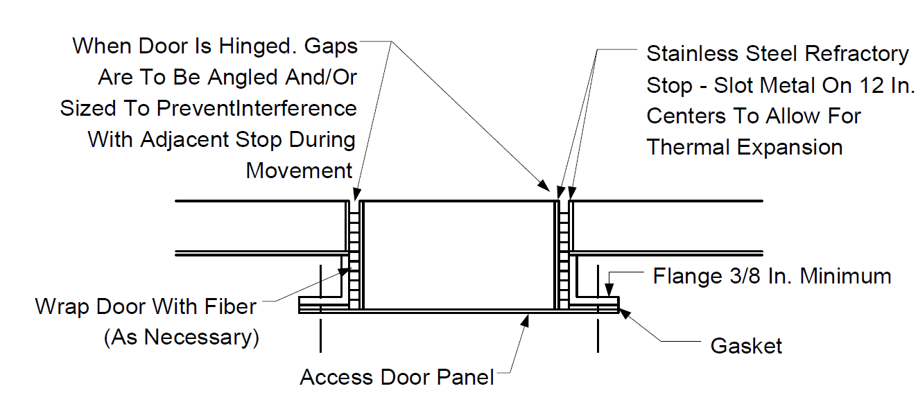
FIGURE 3A
STUDS FOR “SINGLE LAYER” LINING


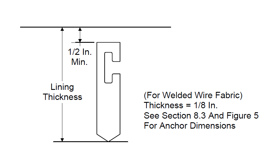
FIGURE 3B “SINGLE LAYER” LININGS
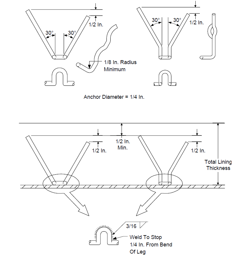
FIGURE 3C
STUDS AND ANCHORS FOR DUAL LAYER LINING
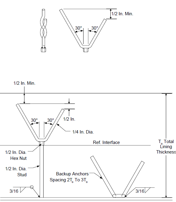
FIGURE 4
ANCHOR PATTERNS FOR CASTABLES
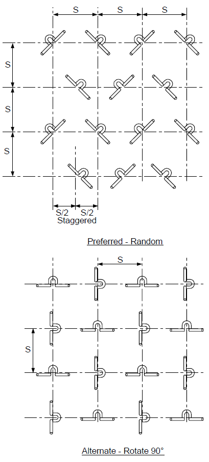
FIGURE 5
WIRE MESH ANCHOR SPACING FOR STACKS AND ROUND DUCTS
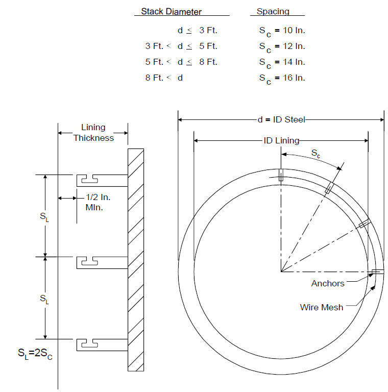
FIGURE 6
ANCHOR TIE BACK FOR BRICK LINING
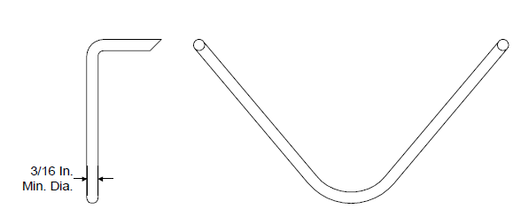
FIGURE 7A & B
ANCHOR PATTERN AND SPACING FOR COMPRESSION & LAP JOINTS OF CERAMIC FIBER BLANKET
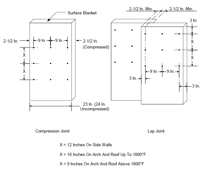
FIGURE 8 OBSERVATION DOOR DETAIL
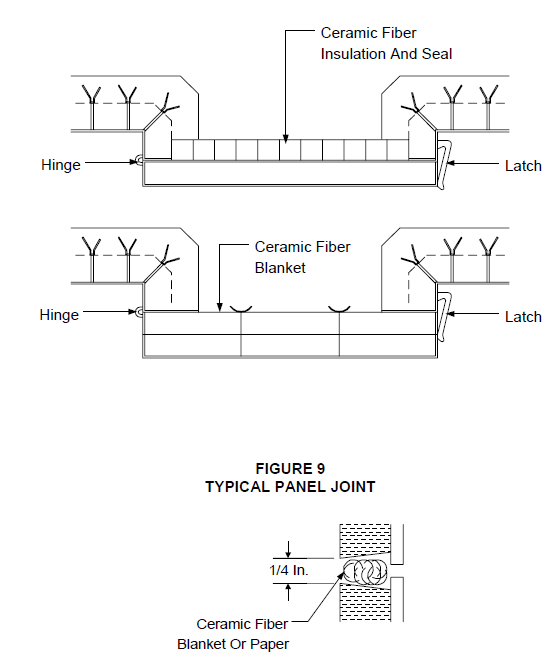
FIGURE 10
REPAIR OF CASTABLE LININGS

Plate
Old Insulation
NOTES:
- Repair shown (including 3 anchors) is the minimum allowable size.
- The periphery of any repair shall be located midway between studs as shown.
- The hole should be cleared of all loose insulation and adjacent material should be thoroughly wetted or painted with mortar before insulation is applied.
© 2026 Inflection Point Engineering, LLC. All rights reserved. The content of this page — including calculation methods, reference data, written analysis, interactive tools, and source code — is the intellectual property of Inflection Point Engineering, LLC and is protected under applicable copyright, trademark, and trade secret laws. Unauthorized reproduction, redistribution, modification, or derivative use in whole or in part is prohibited without prior written consent.
Disclaimer. This material is provided for informational and educational purposes only and does not constitute professional engineering advice. Calculations, reference data, and methodologies are based on published standards and accepted engineering practice but are not a substitute for engineering judgment, site-specific analysis, or review by a licensed Professional Engineer. Inflection Point Engineering, LLC makes no warranties, express or implied, regarding the accuracy, completeness, or fitness for a particular purpose of any content presented here, and shall not be liable for any direct, indirect, incidental, or consequential damages arising from its use. Users assume all risk associated with applying this content to real-world design, operations, or decisions.
© 2026 Inflection Point Engineering, LLC. All rights reserved.