 Section 11 — Refractory, Insulation & Fireproofing
Internal Insulating and Refractory Linings
IPE Engineering Practice IPE-EP-11-1-1
Document number: IPE-EP-11-1-1 · Section: 11 — Refractory, Insulation & Fireproofing
20.0 GUARANTEE 25
21.0 TABLES 26
Table 1 Anchor Design Temperture 26
Table 2 Anchor Spacing 26
Table 3 Limits Of Range Of Acceptable Results 27
Table 4 Documentation Requirements For Refractory Per EP 11-1-1 28
22.0 FIGURES 29
Figure 1A Detail Of Manhole Lining 29
Figure 1B Large Diameter, No Internal Piping, Hot External Piping, Hot Vessel,
Abrasive Service 30Abrasive Service 30
Figure 1C Large Diameter, No Internal Piping, Hot External Piping, Cold Vessel,
Non-Abrasive Service 31Non-Abrasive Service 31
Figure 1D Large Diameter, No Internal Piping, Cold External Piping, Cold Vessel,
Non-Abrasive Or Single Component Abrasive Service 32Non-Abrasive Or Single Component Abrasive Service 32
Figure 1E Large Diameter, Internal Piping, Hot External Piping, Hot Vessel,
Abrasive Service 33Abrasive Service 33
Figure 1F Large Diameter, Internal Piping, Hot External Piping, Cold Vessel,
Non-Abrasive Service 34Non-Abrasive Service 34
Figure 1G Large Diameter, Internal Piping, Hot External Piping, Cold Vessel,
Abrasive Service 35Abrasive Service 35
Figure 1H Large Diameter, Internal Piping, Cold External Piping, Cold Vessel,
Non-Abrasive Service 36Non-Abrasive Service 36
Figure 1I Large Diameter, Internal Piping, Cold External Piping, Cold Vessel,
Abrasive Service 37Abrasive Service 37
Figure 2A "Single Layer" Linings 38
Figure 2B Studs And Anchors For Dual Layer Lining 39
Figure 3 Anchor Patterns For Single Layer Linings 40
Figure 4A Required Hexmesh Type 41
Figure 4B Stud And Washer Joints For Dual Layer Lining Using Hexmesh 41
Figure 5A Hexmesh Details At Lined Nozzles 42
Figure 5B Hexmesh Details At Unlined Nozzles 43
Figure 6A S-Bar Anchors 44
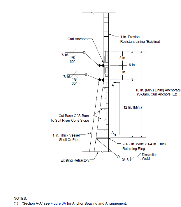
Figure 6B Curl Anchors. 45
Figure 7A 46
Figure 7B 46
Figure 8A Irregular Shaped Panel Joints 47
Figure 8B Aligned, Uncut Joints 47
Figure 8C Unaligned, Uncut Joints 48
Figure 8D Aligned, Cut Joints 48
Figure 8E Unaligned, Cut Joints 49
Figure 8F Joint Of Hexmesh To End Rings 49
Figure 9 Required Hexmesh Details At Field Welded Ends 50
Figure 10 Details At Hexmesh Terminations 51
Figure 11 Castable Field Joints Make-Up Details 53
Figure 12 Repair Of Castable Linings 54
Figure 13 Transition Section Details (Field Weld And Installation) 55
1.0
1.1
1.2
1.3
1.4
1.5
1.6
1.7
1.8
2.0
SCOPE
This Practice governs the general requirements for the application and design of all internal insulating and refractory lining for new installations and repairs in pressure equipment to protect against excessive temperatures, erosion, abrasion and corrosion.
The contractor may quote alternates to this Practice; however, all variances must be clearly indicated at the time of proposal and are subject to Inflection Point Engineering, LLC approval.
Inflection Point Engineering, LLC requires (5) days notice before any phase of refractory installation can begin.
An asterisk (*) indicates that a decision by the Owner or Owner's Engineer is required or that additional information is furnished by the purchaser.
Vendor drawing and data requirements are stipulated in Table 4.
Any deviation from this Practice must be approved by the procedure described in EP 1-1-3.
This Practice is appropriate for attachment to an inquiry or purchase document when accompanied by the referenced IPE Engineering Practices and the completed data sheets.
A revision bar indicates all changes made to this Revision.
REFERENCES
The latest edition of the following publications are referred to herein.
STANDARDS AND PUBLICATIONS
| IPE Engineering Practices |
|---|
| EP 1-1-3 Deviations to IPE Engineering Practices EP 5-5-1 Piping Fabrication |
| ASTM Standards |
| C133 Cold Crush Strength and Modulus of Rupture C704 Abrasion Resistance of Refractory Materials at Room Temperature C860 Practices for Determining Consistency in Refractory Concretes |
| SSPC Standards |
| SP6 Commercial Blast Cleaning SP10 Near White Blast Cleaning |
DEFINITIONS
- Contractor - Company or business that agrees to furnish materials or perform specified services at a specified price and/or rate to the Owner.
- Erosion resistant lining - A layer of dense erosion resistant hydraulic setting castable refractory.
4.0
5.0
5.1
5.2
6.0
6.1
6.2
Extreme erosion resistant lining - A layer of super-duty erosion resistant hydraulic setting refractory, air setting chemically bonded castable refractory, or plastic refractory.
Inspector - A Inflection Point Engineering, LLC appointed engineer or inspector.
Manufacturer - The recipient of a direct or indirect purchase order for materials and/or equipment. In this context, a direct order is one issued to a manufacturer by a contractor or the Owner. An indirect order is one issued to a manufacturer by a vendor (recipient of a direct order) for materials, fabricated components, or subassemblies.
Owner - Inflection Point Engineering, LLC
Owner's Engineer - A Inflection Point Engineering, LLC appointed engineer.
Purchaser - The party placing a direct purchase order. The purchaser is the Owner's designated representative.
Refractory Class: Light Weight - materials having an installed fired density of 75 pcf or less.
Refractory Class: Medium Weight - materials having an installed fired density greater than 75 pcf and less than, or equal to, 120 pcf.
Refractory Class: Heavy Weight - materials having an installed fired density greater than 120 pcf and less than, or equal to, 150 pcf.
Refractory Class: Dense - materials having an installed fired density greater than 150 pcf.
JOB SPECIFICATIONS
IPE shall issue specific requirements for refractory lining of a particular piece of equipment. This shall include type of refractory system, thickness, material, method of refractory support and process conditions. For repair or replacement of refractory the job specification shall define the extent of refractory removal, cleaning etc. which is required. Plant safety rules will be included as necessary.
CONTRACTOR SPECIFICATION
The lining contractor is expected to install refractory in strict accord with manufacturers' recommendations and the more general requirements of this practice. Conflicts will be resolved by Owner's Engineer.
Prior to application, the lining contractor must prepare a written supplemental specification and obtain approval of both the Owner's Engineer and the refractory supplier. The supplemental specifications must cover the installer's application procedures and include specific requirements for mixing, applying, curing, etc.
DOCUMENTATION
All material properties shall be tested to ASTM Standards. Any deviations shall be reported to Owner's Engineer.
Data sheets showing gunned physical properties shall be supplied for all products to be pneumatically applied.
- Bid Stage: The information in the attached data sheets shall be supplied at the bid stage to assure complete evaluation.
- Final Design Approval Stage: The following information shall be supplied for approval by Owner's Engineer for all final lining designs (i.e., after the order is placed):
- Data Sheets
- Any changes from proposal information:
- Refractory brand specified on drawings or proposed by the installer.
- Steel fiber reinforced refractory (if applicable).
- Name and telephone number of reference contacts at plants for whom the refractory installer, within the past 2 (two) years, has applied the type of refractory covered by this project.
- Shipping and handling procedures for all refractory lined equipment and component parts shall be submitted for approval of Owner's Engineer. Sufficient detail, including shipping supports, shall be provided to show that the parts will not be damaged by the usual handling and weather to be expected in transit and at the erection site.
- Final Records: Per Data Sheets.
DESIGN
- The design and thickness of all cold wall linings shall be such that the shell metal temperature is less than one-half the design temperature of the shell (not to exceed 450°F) with an ambient air temperature of 80°F and zero wind. Carbon steel and Cr-Mo vessels in hydrogen service shall not exceed 325°F shell temperature. For the design of repairs to existing equipment, the shell temperature may be extended to the design metal temperature, with approval of the Owner's Engineer.
- Minimum shell temperatures to prevent corrosive condensates forming at the shell shall be reviewed and approved by Owner's Engineer.
- The refractory and insulating material of any layer shall be suitable for a service temperature of at least 400°F above its calculated hot face temperature. Minimum service temperature for refractories at the hot face shall be 2000°F.
- Hydrogen service requires special consideration with respect to shell metal temperature due to increased conductivity caused by hydrogen permeation. Design characteristics shall be approved by Owner's Engineer.
- Manhole details shall be as shown in Figure 1A. Nozzle details shall be shown in Figure 1B through Figure 1I.
- Thermal expansion of the shell shall be taken into account in the refractory design to ensure proper expansion is provided.
ANCHORS
- General
- Selection of materials for anchoring components shall be based on the maximum design temperature and corrosion resistance of the material (refer to Table 1).
- Anchor temperature calculations shall be provided for all operating and regenerating conditions.
- Austenitic, inconel, and RA330 materials shall be supplied and installed in the fully bright solution annealed condition. Anchors shall be clean and free of oxidation coatings. Anchors shall not be formed after annealing. Bending of anchors, after welding, for height adjustment is not allowed without approval of Owner's Engineer. See material testing requirements of this practice.
- All anchors (including hexmesh) shall be completely free from dirt, grease, oil or other deleterious materials.
- Vee and Longhorn Anchors
- Acceptable anchors for single and dual layer linings are shown in Figure 2A and Figure 2B. Anchor pattern is shown in Figure 3.
- The installed anchor height shall be designed for 1/2 inch less than the lining thickness. Refractory lining to cover anchors no less than 1/2 inch minimum and no more than 1 inch maximum.
- When anchor tip coatings are specified, the tips of all anchors shall be coated with mastic or plastic that will burn off during dryout and provide allowance for anchor expansion during unit operation. The coating shall extend from the tip of the anchor to past the first bend (1 inch maximum).
- The maximum anchor spacing based on the full thickness of the linings is shown in Table 2.
- Hexmesh
- Hexmesh shall be austenitic if attached to stainless steel components, and 410S when low chromes up to 12 Cr or carbon steel components are used.
- Hexmesh shall be 14 USS gauge and 1 inch deep hexmesh unless 3/4" deep is specified by Owner's Engineer. Hex section shall be approximately 1-7/8 inch x 1-7/8 inch and shall have, as a minimum, two 1/4 inch wide by 1/2 inch long lances projecting into the hex areas. Lances shall not be opposite each other, and shall be located at the center of the hexagon depth. See Figure 4A, "Required Hexmesh Type". Hexmesh strips shall be tightly joined at each contact point by rivets or by double tabs. For diameters 14 inches and less only riveted hex mesh shall be used.
- Where drawings or the job specs specify raised bar hexmesh, hexmesh shall be 14 USS gauge, 3/4 inch deep with every other bar 1 inch deep. Small pieces of hexmesh (less than 24 inches square) shall be 1 inch deep with no raised bars and every hex shall be welded.
- Raised bar hexmesh shall be used only when the hexmesh is welded directly to the shell.
- Studs and washers for dual layer linings with hexmesh are shown in Figure 4B. Studs shall be on 9 inch centers max. Studs and washers shall be the same material as the hexmesh.
- Nozzle details shall be as shown in Figure 5A and Figure 5B.
- Stainless steel fibers shall not be used with hexmesh.
- Refractory shall not be gunned into hexmesh.
8.4
8.4.1
8.4.2
8.4.3
8.4.4
8.4.5
8.5
8.5.1
8.5.2
8.5.3
8.5.4
8.5.5
8.6
8.7
8.7.1
8.7.2
8.7.3
S-Bars
S-bars shall be 14 USS gauge (min.).
Acceptable anchor patterns for S-bar anchors are shown in Figure 6A.
S-bars may be used in linings less than 3 inches, and shall extend through the full thickness of the lining.
Refractory shall not be gunned into S-bars unless approved by the IPE Engineering Practices Technical Committee's Engineer. Casting, ramming, or handpacking is acceptable.
Stainless steel reinforcing fibers, 2-3% by weight, shall be added to the refractory material.
Ceramic Anchors
The maximum anchor distance from an edge or discontinuity is six (6) inches.
Ceramic anchors shall have a maximum spacing of 12 inches for overhead and 18 inches for side walls.
Ceramic anchors shall be handled with care to avoid cracking or chipping.
When rammed refractories are used, a metal anchor form or dummy anchor is required to seat the anchor in the refractory.
Ceramic anchors shall be installed flush with the hot face of the refractory lining.
Curl Anchors
Acceptable anchor pattern for curl anchors is shown in Figure 6B.
Other Metallic Components
Unless otherwise specified on purchaser's drawing(s), shrouds, metal strips, reinforcing bars, etc. required for nozzles and manways shall be supplied by vessel or piping vendor.
Unless otherwise noted on purchaser's drawing(s), nozzle liners and collars around nozzles and projections shall be 304 stainless steel.
Material for end and taper rings shall be:
- If underlying steel is ferritic in nature: 410S stainless steel.
- If underlying steel is austenitic in nature: 304 stainless steel.
EROSION RESISTANT LININGS
- Extreme erosion resistant linings 1 inch thick shall be retained with S-Bars, Curl anchors, or 1 inch hexmesh. The use of offset hex shall be specifically approved by Owner's Engineer.
- Extreme erosion resistant linings 3/4 inch thick shall be retained with S-Bars or hexmesh. See Figure 6A, Figure 7A and Figure 7B. The use of alternate anchoring systems shall be approved by Owner's Engineer.
- Erosion resistant or semi-insulating erosion resistant linings greater than 1 inch but less than 3 inches thick shall be retained with S-Bars. Linings 3 inches and greater shall be retained with vee or longhorn anchors.
CASTABLE LININGS
- Materials containing calcium silicate-type binders (portland cement) shall not be used.
- For multi-layer castable linings, the minimum thickness of the facing material shall be 3 inches, unless the hot face is an erosion resistant lining.
- For single-layer linings, the minimum thickness shall be 3 inches. Transition sections requiring thicknesses less than 3 inches shall be outlined in Figure 13.
FIBER ADDITIONS
- Stainless fibers shall be used to reinforce linings in areas where mechanical abuse, thermal shock, or erosion is a problem, and when S-bar anchors are used.
- The quantity of fibers shall be 2-3% by weight of the castable. Fibers shall not be added to lightweight insulating castables, or used with hex mesh.
- The refractory shall be reinforced with either 302 or 304 stainless steel fibers. Unless otherwise approved in writing by the purchaser, fibers shall be supplied in the annealed condition. Wire drawn fibers shall not be used. Details of the fiber reinforcement required are as follows.
- For pneumatically gunned refractory, and plastic linings less than 2 inches thick, the reinforcing fibers shall be 3/4 inch long by 0.02 inch diameter.
- For cast refractory, the reinforcing fibers shall be 1 inch long by 0.02 inch diameter.
- Non-metallic fibers (ex. RFT or C-cured) may be used with approval from Owner's Engineer.
SURFACE PREPARATION
- All surfaces to which refractory is to be applied either metal or refractory (including edging bars, anchors, hexmesh, and vapor stops) shall be cleaned and made free of loose particles or materials deleterious to the refractory. Clean metal surfaces free of loose rust, dirt, grease or oil are acceptable metal surfaces for most linings covered under this Practice.
- All surfaces to which a shell coating is to be applied, for corrosion protection, shall be sandblasted to a near white blast finish (SSPC-SP10). If the shell is allowed to sit, and rust forms, then the surface shall be re-sandblasted.
- Acceptable shell coating: silicone paint, Dampney 260-Line or Carboline 1248 (or equal). Sodium silicate shall not be used. Shell coatings shall be applied after the anchors are welded in accordance with manufacturer's recommendations. Verify shell temperatures do not exceed the temperature rating of the coating.
- Sandblasting of surfaces which do not require a shell coating shall be governed by the following guidelines:
- Components that have previously been in operation shall be sandblasted prior to the welding of anchors and other metal components.
- New ferritic alloy steel components shall be dry sandblasted after welding of anchors and other metal components, and after any postweld heat treatment that might be involved, but before the application of refractory. Areas to which metal components are to be welded shall be spot cleaned prior to welding.
- Criteria for sandblasting and cleaning of new carbon steel or austenitic alloy steel components shall be the same as paragraph 12.4.2 above, except at the inspector's discretion, and approval of Owner's Engineer, sandblasting may be omitted in which case purchaser shall receive a price deduct.
- Sandblast to a standard commercial finish (SSPC-SP6) to remove all paint, rust, loose mill scale or other foreign material. The point of welding anchors must be completely clean metal.
- If sandblasting is not required, or a tight scale remains on the shell after sandblasting, the areas where metal components/anchors are to be welded shall be ground to clean metal prior to welding.
- After sandblasting, the interior of the vessel shall be cleaned. Do NOT wash with water.
- Before commencing any section of work, an adequate area of surface and work area must be cleaned and prepared to ensure that the work can proceed in an orderly and workmanlike manner without danger of incorporating dirt, debris or dehydrated materials in the work.
- Refractory placed over or against improperly cleaned surfaces will be rejected. The inspector shall verify cleanliness prior to the start of installation.
- Supporting members, pipe sleeves or exposed structural items within the limits of an installed lining, shall be wrapped with 1/8 inch (min) ceramic fiber paper, ceramic fiber blanket, or coated with 1/8 inch stelastic.
INSTALLATION OF ANCHORS AND OTHER METALLIC COMPONENTS
- Anchor installation
- When laying out anchor locations, a waxed crayon shall not be used since this may cause poor contact between anchors and shell.
- All refractory anchors shall be welded in place prior to any required post weld heat treatment.
- Anchors shall be hand welded and completely encircle the anchor. See Figure 2A, Figure 6A, Figure 6B, Figure 7A, Figure 7B, and Figure 10 for weld details. Chip all slag from welds. See Section 19.4.5 for test requirements and Section 12.0 for surface preparation requirements.
- The weld on an anchor foot shall stop 1/4 inch from the bend of the anchor leg.
- Maximum anchor distance from an edge or discontinuity shall be 3 inches.
- Hexmesh Installation
- Hexmesh panels, or sections, shall be rolled in the direction most resistant to rolling (i.e the "hardway"), and shall be sufficiently rigid so they will not flex between points of attachment to the shell. It is important that as few passes through the rolls as possible be made. Where it is unavoidable to bend the hexmesh in the direction least resistant to bending (which opens the crimped fingers), the hex shall be welded the full depth of each hex prior to rolling. In cyclone horns and barrel sections, mesh ends shall be installed perpendicular to flow.
- Hexmesh shall be installed in sections which are as large as possible, and shall be welded per Figure 7A and Figure 7B. For dual layer linings leave a 1/4 inch gap between the backup lining and the hexmesh. All junctures of hexmesh shall be welded together.
- Longitudinal joints of hexmesh shall be offset 2 inches minimum to avoid continuous seams.
- When small or irregular pieces of hexmesh are used, every end of the hexmesh shall be welded to adjacent hexmesh or banding bars in accordance with Figure 8A, Figure 8B, Figure 8C, Figure 8D, Figure 8E, and Figure 8F, "Required Details for Hexmesh Joints". For pieces smaller than 4 square feet weld every hex to the shell.
- For dual layer linings, if small or irregular pieces of mesh are used, at least three (3) studs shall be installed for each square foot of mesh. Also, the hexmesh piece shall be joined by welding to the adjacent hexmesh through the full depth of the hexmesh strips, or the repair procedure listed in 17.3.3 may be used.
- When irregular panels of hexmesh are used, panels intersecting at an angle (ex. nozzle) or pie shaped panels in a head, weld panels to a banding bar per Figure 8A. Banding bars shall be made from flat bar, material to be the same as hexmesh, not from a strip of hexmesh which has been flattened.
- Intermediate end rings or banding bars with refractory on both sides shall have 1/4 inch diameter holes on 1 inch centers.
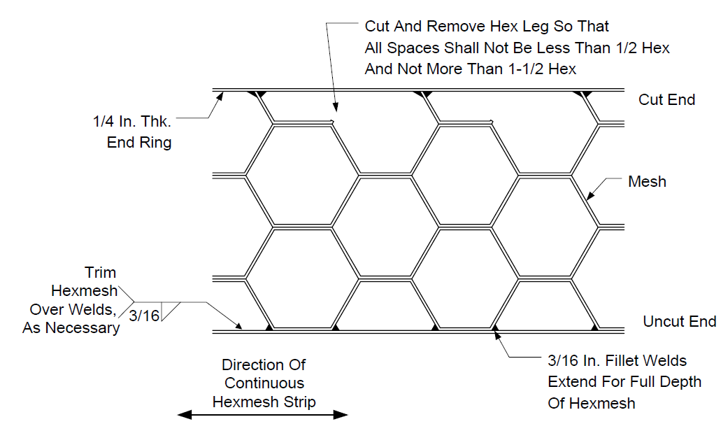
- At joints between panels and at projections through the hexmesh, individual hex openings shall not be more than 1-1/2 times the area and not smaller than 1/2 the area of a standard hex.
- Splices between hexmesh sections and terminations of hexmesh shall meet with requirements of Figure 8, Figure 9, and Figure 10.
- Ceramic Anchors
- Ceramic anchors shall not be struck without first protecting the anchor. Anchors shall not be thrown, dropped or roughly handled. Discard all damaged anchors.
- Ceramic anchors shall be installed in a plastic lining per the following procedure:
- The wall shall be built up slightly above the elevation where the anchor is to be installed.
- Set a metal anchor, or dummy anchor, into the clip and pull forward to ensure it is properly engaged.
- When the anchor lies true and level, and is fully supported on the plastic for the full length, the anchor shall then be set by a few blows of a hammer.
- Remove the dummy after printing the plastic. Then set the ceramic anchor without hitting the anchor.
- When the wall has been built to a suitable height, a hammer with a rubber head shall be used to tighten the plastic around the heads of all the anchors.
REFRACTORY HANDLING AND SHIPMENT
- Shipment of hydraulic setting refractories shall be scheduled to insure that age of binder cement is less than 3 months old at the time of shipment and less than 6 months old at time of refractory installation. Any material over 6 months old, may be rejected by Owner.
- Chemically bonded refractories and plastics shall be less than one month old at time of shipment and less than 3 months old at time of installation. These materials are subject to discarding after 3 months.
- Each bag or box of refractory shall be identified by the date of the manufacture. Each pallet shall be numbered in a minimum of three locations on the pallet to assure batch identification. When products are manufactured specifically for a project, the pallets shall be numbered sequentially and in the order of the manufacture.
- Chemically bonded refractories shall be shipped in vapor tight plastic enclosures protected from mechanical damage. Each container shall be marked with a code date of manufacturing and pallet numbers. Materials for field linings shall be shipped in metal outside containers.
- For field or shop linings, protection from moisture shall be provided during shipping, handling, and storage. Material longest in storage shall be used first.
- The equipment fabricator shall be responsible for protecting, during shipment, equipment with refractory installed prior to arrival at the job site. Repair of a lining damaged during shipment is the responsibility of the equipment fabricator.
- For shop lined panels, panels shall be packaged to minimize abrasion to the lining surface during shipment.
- Any opened or damaged refractory shall be discarded. All refractory exceeding its shelf life shall be discarded.
INSTALLATION OF REFRACTORY
- General
- Equipment lined with hydraulic bonded refractories shall not be moved for a minimum of 24 hours. The equipment may be rotated to facilitate the continuance of the lining installation after all of the lining has begun hydration and has taken an initial set.
- Prior to refractory installation, all piping sections to be lined shall be match marked and provided with truing rings by piping fabricator. Hammering or deforming of fully lined pipe to effect joint
fit-up is not acceptable.
- All water used for mixing refractory must be clean, potable, have no more than 150ppm chlorides (50 ppm for stainless equipment), and may vary between 50F and 90°F. Water temperature may be used to help conform to mix temperature requirements where appropriate.
- Firewater SHALL NOT be used.
- All damaged or wet bags of refractory shall be discarded. Fractional parts of a bag shall not be used.
- It is important that the mixer and all tools be thoroughly cleaned prior to use, and that no traces of deleterious materials such as portland cement, acids, sodium silicate, or other binders foreign to the type being used are present. Foreign materials, such as paper from the bags, shall be removed. Contamination will detrimentally affect the properties of the refractory.
- (*)Contractor is responsible for maintaining all equipment used on the project in acceptable working condition. All equipment not meeting IPE Standards may be rejected by Owner's Engineer.
- Forms
- All forms must be cleaned and waterproofed prior to use.
- If forms are removed prior to the specified minimum curing time, then an approved curing procedure must be commenced immediately.
- Forms for thick plastic linings, greater than 3 inches thick, must be strong enough to withstand, without deflection, the ramming loads imposed. Corbelled or overhead areas may require forms that are left in place until after the plastic has heat cured.
- Sections of built-up forms shall be secured to facilitate uniform lining thickness and prevent shifting during installation of the lining.
- All form work shall be removed. Burnout of forms is not permitted.
- (*)Proposals to vibrate forms or use other types of vibration shall be submitted to Owner's Engineer for approval.
- When stainless steel fibers are used, particular attention shall be given to insure that the fibers are uniformly distributed in the refractory. For fibers added in the field, fibers shall be added after refractory has been placed in the mixer. Fibers shall be introduced in a "rain" of individual fibers to prevent clumping of the fibers. Fiber shall be distributed through a shaker box with a mesh size of 1/2 inch.
- Plastic requiring fibers shall have the fibers added by the refractory manufacturer.
- The final installed thickness shall be design thickness (-) 0 inch, (+) 1/4 inch. For linings less than 3 inches the final installed thickness shall be (-) 0 inch, (+) 1/8 inch. Linings in hexmesh s- bars, or similar type anchors, shall comply with paragraph 15.5.3.
- Refractory anchors, hexmesh, and surfaces on which erosion resistant refractory will be applied shall be checked for cleanliness and for compliance with disregard attachment requirements of this Practice.
- In multi-layer linings, anchors for the facing (top) layer shall be clean and free of all back up refractory before application of the second layer.
- Hydraulic Setting Castables
- General
- The water level used to mix castable refractories shall be kept at the optimum water level. At no time is the castable manufacturer's recommended water to be exceeded. The "Ball in Hand" method, ASTM C860, shall be used, as applicable, to determine the optimum water content.
- In cold weather (ambient temperature lower than 60°F) warm water, up to 100°F, can be used to raise the temperature of the mix to between 60 and 90°F.
- In hot weather (ambient temperature higher than 90°F) cold or ice water should be used to reduce the temperature of the mix to between 60F and 90°F to prevent premature setting. No solid ice particles are permitted. Cooling the material may be required to meet the temperature requirements, or facilitate an acceptable installation.
- When the shell or metal temperature is below 50°F, or will fall below 50°F during installation or within 48 hours after placement, the EXTERIOR of the area to be lined shall be insulated or heated prior to and while the refractory is being placed, and while the lining is being cured.
- When the shell or metal temperature exceeds 100°F, the EXTERIOR of the area to be lined shall be cooled by spraying with water prior to and while the refractory is being placed.
- After installation, the lining shall not be allowed to drop to freezing temperatures prior to dryout of the lining.
- Castable shall be stored at 60F - 90°F for 48 hours prior to use.
- The interface surface between a block or ceramic fiber layer and a castable shall be treated to prevent absorption of moisture from and during installation. Treatment shall consist of a resin base membrane curing compound, polyethylene sheet, waxed paper, or the use of a precoated block.
- Additives shall not be added to the mix in the field to quicken or decrease the setting time.
- Depth gauges shall be used to ensure the castable is applied to the correct thickness.
- When interruptions occur in the application of refractory for more than 20 minutes, the refractory shall be cut perpendicular to the hot face where it has been applied to full thickness and at a point midway between the anchors. The edge shall be scored after cutting and thoroughly wetted before application of the adjacent lining.
- Light troweling is acceptable for contouring only otherwise no troweling of castables surfaces is permitted. Cutting-back or screen is acceptable, but the surface should not be "floated".
- When prelined sections are used, the field joint shall comply with the detail shown in Figure 11.
- Castable material shall be applied by pouring or pneumatic gun application ("dry" mix with water addition at nozzle). Gunning grade products shall be used for gunned applications.
- Per paragraph 16.1, a curing compound shall be used on all exposed refractory surfaces. Application of the compound shall be within two hours of material placement.
- Cast
- Casts being made with rotary vibrators, shall use 2 or more vibrators mounted externally on the component being lined. Vibrators shall be spaced on no greater than 4 foot longitudinal centers.
- As a minimum, vibrators should be located 180 degrees apart per level, and rotated 90 degrees every 4 feet. For pipe greater than 72 inches (O.D.), a minimum of three vibrators shall be used at each level. Vibrators shall be located no farther than 1 foot from the edge of the component being lined.
- For cast refractory applications, when stainless steel fibers are used, only enough water (t10%) necessary to keep the dust down shall be placed in the mixer before the refractory and fibers are added to prevent balling of the fibers. The fibers shall be added after the refractory. The remainder of the water shall be added last. A paddle type mortar mixer shall be used.
- For cast and handpacked refractory applications, nozzle necks shall be installed monolithically with the shell, or as an alternate, the nozzles may be installed to within 1 inch of the inside of the shell to which they are attached. The remaining 1 inch shall be cast monolithically with the shell.
- Poured refractory shall be vertically deposited and in a manner which will prevent segregation of the materials. It shall be deposited as practical in its final position with the free fall limited to a maximum of 8 feet Drop chutes may be used.
- If material is cast "downhand" in a cylinder, no more than the bottom 120 degrees may be lined at a time. Timing/requirements for rotating equipment shall comply with paragraph 15.1.1.
- Gunned
- Pneumatic gun application of castables shall start at the lowest elevation and proceed upward to minimize the inclusion of rebound material. Rebound material shall be discarded.
- Guniting of refractory shall be on vertical walls and overhead. No guniting shall be done in the down position (between the 4 o'clock and 8 o'clock position).
- All rebound and loose material shall be removed from the surface of a completed band before proceeding with the next band. All material hung up on anchors shall be cleared off continuously during application. No rebound material shall be allowed to accumulate at any point where the lining has already been applied. All rebound shall be removed and discarded to prevent its inclusion in the lining. Reuse of rebound is absolutely prohibited.
- Application of gunned material shall be limited to an area no greater than 8 square feet until the full thickness of the lining is developed.
- Stop boards shall be used to obtain a full thickness lining at cold joints. All joints shall be perpendicular to the work surface.
- Plastics
- General
- Plastic shall be stored in a cool dry place (55-88°F).
- Forms shall be used for all nose and arch construction.
- Sufficient form work must be supplied to ensure that the completed work can remain fully supported for as long as required without limiting the progress of the balance of the work. Stripping of arch or nose form work shall not take place until the work has progressed far enough that the finished work will not be disturbed.
- When shell or metal temperature exceeds 90°F, the EXTERIOR of the area to be lined shall be cooled by spraying with water prior to and while the plastic is being applied.
- When shell or metal temperature is below 40°F the EXTERIOR of the area to be lined shall be insulated or heated prior to and while the plastic is being applied.
- No placement shall take place below 40°F ambient temperature and falling temperatures.
- After installation, plastic linings shall not be allowed to drop to freezing temperatures prior to the dryout of the lining.
- Cartons of plastic shall not be opened until the material is in the work area. Only enough cartons shall be opened as is required to feed the work face.
- Plastic, when opened, shall be stacked on a work bench or equivalent and shall be handled carefully so as the material is kept clean and not wasted. If the plastic is split on the floor with a spade then a clean surface such as a sheet of plywood shall be put down first.
- All plastics shall be installed by ramming the material thoroughly with a pneumatic hammer with a 2 inch to 2-1/2 inch diameter head. Head diameter shall suit density of plastic. Metal wedged or rounded heads shall be used. Flat heads are not recommended.
- Air pressure to the hammer shall be 90-100 psi.
- Any broken slabs or bits of plastic shall be used at once before they become dry and crumbly.
- After installation and prior to dryout no traffic (i.e. walking) shall be allowed on plastic.
- Linings greater than 3 inches
- Gunned plastics shall not be used without approval of Owner's Engineer.
- A row of slabs shall be laid edge to edge along the length of the work station. Full slabs shall be used at the hot face with half of smaller slabs used in the rear.
- Any holes between the slabs may be filled with clean recovered material keeping this material as far as possible to the rear of the wall.
- Any broken slabs or bits of plastic shall be used at once before they become dry and crumbly.
- The row of slabs shall be completely and thoroughly rammed eliminating all joints and knitting the plastic into a monolithic mass. Each layer of slabs or equivalent shall be rammed out completely before the next layer is placed.
- The maximum layer that may be rammed at any one time shall be 2-1/2 inches thick.
- The direction of ramming in a wall section shall be downward in a vertical direction. The hammer shall be worked backward and forward from the back to the front of the wall while advancing slowly along the wall.
- Ramming on the hot face shall be kept to the absolute minimum necessary to knit the slabs. It is not permitted to keep the wall true to line by ramming the hot face. This shall be accomplished later by trimming.
- The top of the wall shall be kept level from end to end and from front to back at all times.
- After the plastic has been installed, the wall shall then be trimmed true to line.
- All plastic linings shall be vented by piercing the plastic between each anchor to half the depth of the lining with a sharp pointed 3/16 inch diameter rod. Construction joints 2 inches deep or up to 1/3 of the lining thickness shall be cut on no more than 6 foot centers.
- Plastic surfaces must be protected against premature dryout during installation. Any time the work is stopped, the work face shall be covered with a polyethylene sheet to stop the plastic from drying out. The sheet must adhere tightly to the surface to prevent condensation from occurring and "mushing" the surface.
- If the surface dries out despite the covering, it shall be cut to expose a fresh soft face before recommencing work.
- Chemically Bonded
- Refractory shall be stored in a dry, cool place (40F - 80°F) until used.
- Material older than 4 months shall not be used.
- The least amount of water possible (within the specified range) shall be used.
- Refractory that requires more than the specified water to "knit together" shall not be used.
- When air temperature exceeds 80°F cold water may be used to reduce the refractory temperature to between 55°F - 85°F.
- When shell or metal temperature exceeds 85°F, the EXTERIOR of the area to be lined shall be cooled by spraying with water prior and while material is being applied and cured.
- In cold weather, ambient below 50°F, water up to 80°F may be used to raise the refractory temperature to between 55°F and 85°F.
- When shell temperature is below 55°F the EXTERIOR of the area to be lined shall be insulated or heated prior to and while the materials are being applied, and for at least 48 hours thereafter. NO PLACEMENT SHALL TAKE PLACE BELOW 40°F AMBIENT AND FALLING TEMPERATURES.
- Screen the material through a number 4 mesh screen to remove any lumps.
- Weigh the materials to insure that the bags are neither short nor over.
- Premix material in Hobart (or equivalent) paddle type mixer, 20-30 quart bowl. Premixing is to be done at low speed. Mix time shall be a minimum of 1 minute and no more than 3 minutes. This mixture is then divided into equal parts of 12-1/2 lb. batches. Double batches (25 lbs.) can be mixed if two men are applying material. Premixed material must be used within eight hours or discarded.
- Only a Hobart type mixer with stainless steel bowls and beaters shall be used. Between each batch the paddle and drum must be thoroughly cleaned and dried. Check the clearance between the bowl and the beater after each cleaning. Clearance is to be 1/8 to 7/32 inch.
- The mix time shall never be less than two minutes or more than four minutes after the addition of water. Mixing should not continue longer than one minute after a plastic, puttylike consistency occurs.
- Do not make any additions to the above mixture after completion of mixing. If a batch of material should stiffen before actual placement, to a point where it is not knitting together, the batch should be discarded. Under no circumstance should more water be added and the material retempered.
- For new construction, equipment shall be rotated so that all refractory is installed "down hand". In a cylinder, only 120 degrees at the bottom of the cylinder may be lined before rotating the cylinder. Care must be taken that the material is "set" and does not slump when rotated.
- The dipping of tools or gloves in water to facilitate installation or smoothing refractory surface shall not be permitted.
- Placing Around Hexmesh, S-Bars, or Curl Anchors
- Refractory shall be compacted into the anchor system by tamping to eliminate any void in the anchorage holes, and under the hexmesh, curl, and S-bar arms. Do not gunite. Extreme erosion resistant refractory shall be rammed with a pneumatic hammer.
- Depressions or pockets in the refractory, in the hex mesh or under the S-bar legs, are not acceptable.
- The refractory shall be cut FLUSH with the top of the anchor system. All material pulled back from the metal edge shall be retamped into place. If material cannot be retamped, chip out and repair per Paragraph17.3.
- For dual layer linings the backup lining shall be flush with the back of the washer. Leave a 1/4 inch gap between the backup layer and the back of the hexmesh.
- At the end of the application of each batch of refractory, all hexagonal openings in the hexmesh that are partially filled shall be cleaned out. S-bar installations shall be cut back to 1/2 way between anchor rows.
- Install material into S-bars in a band not to exceed 12 inches in width.
CURING
- Curing of hydraulic refractory castables, including lightweight insulators, shall be accomplished by application of a colored membrane curing compound, applied to the exposed castable surface within two hours of material placement to prevent loss of moisture by surface evaporation. This is a continuous process and does not mean after the job is finished. Brand name and description of curing compound to be used shall be submitted for approval to the Owner's Engineer. Wax based sealers are not permitted. For field applications in confined areas spray of fine water may be used with approval by Owner's Engineer. Keep surface damp a minimum of 24 hours.
- During placement, and 48 hours thereafter, the refractory and surface to be lined must be maintained between 50 and 100°F for hydraulic bonded refractory. Thick linings (greater than 5 inches) may require a longer curing period.
- Suitable means for heating or cooling shall be provided. Live steam, however, shall not be used for heating.
- For casting refractory applications and as an alternative to curing compounds, the forms may be left in place for 24 hours, minimum, after casting. This alternative is only acceptable if form details are such that evaporation of moisture from the refractory will not occur. Exposed edges of refractory will still have to be coated. The above procedure does not waive the 48 hour cure period. After the forms are removed the remaining cure time must be realized.
- Field mixed chemically bonded refractory (ex: AA-22) shall be air cured for 48 hours. During the 48 hour air cure, no water sprays or water shall come in contact with the material nor shall it be sealed from contact with the atmosphere (unless specified by the refractory manufacturer). The shell temperature must be maintained at 55°F to 85°F during the 48 hour cure.
- All shop applied linings shall be dried out (heat cured) per section 18.0 with circulating hot air prior to shipping.
- Plastic refractory does not require curing. However, a 7 day air dry is recommended for phosbonded plastics to minimize laminations of the lining. If the lining is to be dried before having a 7 day air dry the dryout procedure in section 18.10.4 shall be followed. The shell temperature must be maintained above 40°F until the lining has been dried out.
REPAIR OF DEFECTIVE AREAS
- Single-Layer Linings or Backup Layer of Multi-Layer Linings
- Defective areas found after curing shall be chiseled out completely to the shell or duct wall and shall be reapplied per Figure 12.
- Repairs to surface detects in vibracast lines shall be determined by Owner's Engineer.
- Dual-Layer Linings
Defective areas found in the facing layer after curing shall be removed to the insulating backup material and the facing castable reapplied. Reference Figure 12 for minimum required replacement area and edge preparation.
- Repairs in Hexmesh
- Loss of refractory from individual "biscuits"- the replacement of a failed or removed single hexmesh "biscuit" requires the removal of the six adjacent hexmesh "biscuits". This is necessary to anchor the new material within the hexmesh.
- If the hexmesh in an existing lining has eroded down to the clinches, both the hexmesh and material must be replaced.
- If extensive repair of the hexmesh and refractory in a dual layer lining is required, the area removed shall expose a minimum of three anchor studs in all directions. A 1/8 inch thick edging bar shall be installed completely around the removed area. The loose ends of the remaining hexmesh and the path hexmesh shall be welded to the edging bar. The material shall then be installed per the appropriate placing instructions. As an alternate the hexmesh "patch" may be welded per section 13.2.5.
- If the insulating backup is broken, the repair requires cutting out the section to the shell per Figure 12.
- Repairs of Plastic Linings Greater Than 3 Inches Thick
- Cracks prior to firing requiring repairs shall only be made just before the unit is heated.
- Surface cracks under 1/8 inch do not require repair at this time.
- All surface cracks 1/4 to 5/8 inches wide or cracks from 1/4 to 3/4 inches in width which go through the full thickness of the lining shall be packed with a 1 to 1 mix of fire clay or the original plastic, and suitable ceramic fiber the full depth of the crack.
- All cracks greater than 5/8 inch wide shall be repaired by cutting the crack out to form a key shape and removing all crusted material. The exposed sides of the crack shall be dampened and plastic of the same quality as the lining shall be rammed into the crack working parallel to the hot face as far as possible.
- Cracks after firing requiring repairs shall be made just before start-up of the unit.
- All cracks over 1/2 inch wide shall be cut to form a key, a suitable expansion joint material shall be applied to one face of the opening and plastic of the same quality as the original lining shall be rammed into place as set out in paragraph 17.4.1.3 above.
- All cracks under 1/2 inch wide which will not close at temperature shall be packed with ceramic fiber and clay as set out in paragraph 17.4.1.2 above.
DRYOUT
After curing, the initial dryout heating of new linings which have been water soaked, shall comply with the following requirements:
- Before dryout begins, sufficient temperature measuring devices shall be installed to monitor gas temperature throughout the lined area to be dried, particularly in dryout burner areas and at the gas exit of the lined areas. On large equipment, duplicate thermocouples should be considered for each location.
- Heat up schedules faster than recommended by the refractory manufacturer shall be avoided to prevent an explosive steam release.
- No lining shall be allowed to freeze prior to dryout.
- If a multiple material lining is used, the slowest heat up schedule should be utilized.
- All shop installed refractory shall be dried out to 1000°F (min) prior to shipment.
- All refractory lined components shall be dried by the application of heat from the inside.
- Proper air circulation for the removal of moisture shall be provided during the dryout process. This is extremely important with plastic refractories and should be maximized.
- If steaming is witnessed, no increase in temperature shall be made until steaming ceases.
- All dryout schedules shall be approved by Owner's Engineer.
- It is not practical to define exact heat up schedules for all equipment since multiple linings and materials can be employed. DRYOUT SHOULD FOLLOW MANUFACTURER'S RECOMMENDED PRACTICE. The following are typical for the materials listed.
- Firing schedule - Light Weight Castables
- Heat at 75°F per hour until all gas temperature monitors are between 300 and 375°F. Hold gas temperature in this range for one hour per inch of thickness.
- Increase gas temperature 75 degrees per hour until all gas monitoring points are between 650 and 750°F. Hold gas temperature in this range for one hour per inch of thickness.
- Heat at 100°F per hour to operating temperature or 1200°F, whichever is less. Hold for 8 hours.
- Cool down at a rate of 100°F per hour (max.)
- Firing Schedule - Medium Weight Castables
- Heat at 50°F per hour until all gas temperature monitors are between 300°F and 375°F. Hold for one hour per inch of thickness.
- Increase gas temperature 50°F per hour until all gas monitoring points are between 650°F - 750°F. Hold gas temperature one hour per inch of thickness.
- Heat at 75°F per hour to operating temperature or 1200°F whichever is less. Hold for 8 hours.
- Cool down at 100°F per hour (max.)
- Firing Schedule - Heavy Weight and Dense Castables
- Heat at 25°F per hour until all gas monitors are between 300°F - 375°F. Hold in this range for one and a half (1-1/2) hours per inch of thickness.
- Increase gas temperature 50°F per hour until all gas monitors are between 650°F - 750°F. Hold in this range for two hours per inch of thickness.
- Heat at 50°F per hour to operating temperature or 1200°F whichever is less. Hold for 12 hours.
- Cool down at 100°F per hour (max.)
- Firing Schedule - Phosbonded Plastics
- Heat at 50°F per hour to 120°F - 150°F. Hold in this range for thirty-six (36) hours.
- Increase gas temperatures 50°F per hour until all monitors are between 300°F - 375°F. Hold in this range for two hours per inch of thickness.
- Heat at 50°F per hour to 700°F - 800°F. Hold in this range for two hours per inch of thickness.
- Heat at 50°F per hour to operating temperature. Hold for four (4) hours.
- Cool down at 100°F per hour (max.).
- During start-up and assuming that the dryout procedure above has been performed, the system shall be brought to operating temperature per the procedure outlined below. Temperatures indicated are gas temperatures.
- Bring up at rate not exceeding 100°F per hour until operating temperature is reached.
- In cooling, do not exceed a cooling rate of 100°F per hour.
- A furnace with no means to circulate hot air through the equipment shall not be used for dryout.
- Equipment which has been hydrotested after refractory dryout shall be redried the same as a new lining.
INSPECTION AND TESTING
- Material Qualification
- All test specimen preparation and testing (including sampling) conducted by the refractory manufacturer and application contractor shall be witnessed by the Owner's Inspector. Tests shall be performed by a qualified laboratory. The Inspection lab shall be approved by Owner's Engineer.
- The application contractor shall be responsible for arranging and paying for testing of materials from the refractory manufacturer, unless material is purchased directly by the Owner, and for any prequalification testing of their personnel and procedures. The Inspection lab shall be approved by Owner's Engineer.
- Unless otherwise specified in the purchase order, the application contractor shall be responsible for arranging and paying for production samples of shop lined items.
- The Owner shall be responsible for arranging and paying for testing of production samples prepared in the field. If production samples fail, the application contractor will be responsible for paying for any retests, as well as all costs associated with removing and reinstalling new material.
- The contractor, who installs the anchors, shall verify by random checks of metal composition that the anchors being installed meet the required material specification (anchor diam., height, bend radius, etc.). Minimum sampling shall be one per 1,000 anchors of each design (materials, size). These results shall be supplied to the Owner's Engineer.
- Refractory Manufacturer Requirements
- The refractory manufacturer or an approved test laboratory shall provide test results of each batch to the Owner's Engineer, inspector, and the refractory contractor for all materials received as part of each order. The tests shall consist of Erosion Loss where applicable, density cold crush, modulus of rupture and permanent linear change. The refractory manufacturer shall certify that all materials are within specification for the material. (No individual sample is allowed outside of published ranges).
- Inspection requirements shall comply with paragraph 19.1.1.
- The following data shall be supplied: compressive strength, density, permanent linear change, erosion loss, and required water % (as applicable).
- For extreme erosion resistant materials the erosion loss, as certified by the refractory manufacturer, of each of the test specimens when determined per ASTM C704-88 shall be no greater than 6cc's.
- Each bag shall be marked as to manufacturer's run and batch number and date of manufacture. Material should be supplied in consecutive pallets.
- Production Sampling
- Production sampling shall be accomplished by the applicator during installation. All samples shall be submitted to an independent laboratory for testing. The Owner's Inspector shall determine which samples shall be tested. Random samples shall be taken of each different material based on the following schedule:
- One (1) sample per installer, per shift for each different material.
- For plastic refractory, one sample per shift for each different material.
- Test Specimen Preparation
- Specimens:
- Compressive strength; 2 x 2 x 2 inch cubes.
- Linear change: 2 x 2 x 9 inch bar.
- Erosion loss: 4-1/2 x 4-1/2 x 1 inch plate.
- Dimensional limits shall be ± 1/64 inch and 90° ± .05°, whether cast or saw cut preparation.
- For extreme erosion resistant material, each sample shall consist of three (3) compressive strength specimens. Determine the density for each cube. Also two (2) erosion loss specimens shall be taken.
- For cast refractory, each sample shall consist of 9 x 4-1/2 x 4-1/2 inch bricks, from which three compressive strength specimens, one (1) linear change bar and two (2) erosion loss specimens shall be cut. Test the cubes for cold crushing strength and density. Vibration cast molds shall be vibrated with the form being cast.
- For gunned refractory, a wire mesh "basket" 12 inches square by 4 inches deep, constructed of 1/2 inch wire mesh shall be placed on the wall, gunned, filled, and removed. All loose and rebound material shall be removed/cleaned from the area where the basket was filled. From the sample basket cut three (3) compressive strength cubes, one (1) linear change bar, and two (2) erosion loss specimens. Test the cubes for cold crush strength and density.
- Specimen Testing Procedure
- Compressive strength test methods shall conform to ASTM C133.
- Permanent linear change. Measure at room temperature the length of each specimen in the 9 inch direction after drying at 230°F and again after heating to 1500°F. Report the percentage of linear change based on the length measured after drying.
- Bulk density of compressive strength cubes. After drying and heating/cooling (to 1500°F), the specimens shall be measured, and weighed to the nearest 0.002 pounds. Density shall be reported in lb/cu. ft.
- Erosion loss test methods shall conform to ASTM C704-88.
- All tests shall be performed according to appropriate ASTM Standard by a qualified laboratory.
- Records shall be kept for each batch of material mixed by an installer. Records shall include (as applicable) material name; mixing time; ambient, surface, and material temperatures; fiber content, installer's name (include nozzleman and gun operator); and location of installation (map) within the equipment.
- A system of tagging each test sample with the area in which the material was installed shall be established so that rejected material can be removed.
- If required in the purchase order testing of any other property listed in the specification sheet shall be accomplished by an independent laboratory. The frequency of sampling and size of samples for these additional tests shall be stated in the purchase order.
HEAT CURING (DRYOUT) IS NOT PERMITTED UNTIL FIELD TEST REPORTS ARE APPROVED.
- Acceptance/rejection criteria of field or shop installed refractory materials shall be based on the manufacturer's certified properties supplied in the proposal and approval stage documentation. Unsatisfactory test results are cause for rejection. The range of acceptable variation from specified properties is shown in Table 3.
- Installation Qualification
- Installers shall submit copies of prequalification documents to Owner's Engineer and inspector stating prequalification testing performed in accordance to this document.
- Gun Applied Castables
- All nozzlemen shall be qualified by shooting one 3 x 3 foot sample panel of each material to be used, the thickness of the lining and the anchor system is to match job requirements. The anchors shall be bolted to the form to permit removal of the panel after the castable has set. Each nozzleman must pass this test prior to commencing work. The test panel shall be done with actual job site equipment using the same mixing and application procedures specified for the field lining, and shall simulate an "overhead installation" of the lining with the forms inclined overhead at 45 degrees.
- Each sample shall be tagged with the following information: name of nozzleman, material used, and date and time prepared.
- The refractory installer shall provide the test panels with the anchors installed.
- After curing, a set of three (3) compressive strength, two (2) linear change, and two (2) erosion loss specimens shall be cut from each panel. The remainder of each test panel shall then be broken into pieces to insure the uniform distribution of any steel reinforcing fibers, the absence of voids and rebound, and sound anchorage.
- The specimen cut from the panels shall be dried and tested per ASTM specifications. Density shall also be reported. Unsatisfactory test results are cause for rejection. No more than one retest will be allowed per installer.
- Poured Castables
- For vibration cast linings a mock up simulating the actual installation shall be made using at least two vibrators mounted externally on the mock up test piece. The test is to verify the vibrators are capable of "moving" the material with the water ratio specified. Test specimens shall be made by vibrating the sample molds on the mock up piece.
- Castable specimens shall be formed in 9x4-1/2x4-1/2 inch molds. Specimens shall be cut from the large unmolded samples.
- A series of tests is required for each set of castings. Samples shall be prepared using the same procedures (water, temperature, etc.) and equipment as specified for each material to be used for the actual refractory lining.
- If all casting is to be done at the same conditions, only one series of tests is required per material.
- A series of tests shall consist of two (2) sets of specimens. Each shall consist of three (3) compressive strength, two (2) linear change, and two (2) erosion loss specimens. Density shall also be reported. The refractory applicator should vary the water content of the two sets as follows:
- One set shall have the maximum water recommended by the refractory manufacturer.
- One set shall use the optimum water content as determined by the "Ball in Hand" method, ASTM C860.
- Thin Erosion Resistant Linings 1 inch and less
- A series of tests shall be performed prior to installation. Samples shall be prepared using the same procedure (water, temp., etc.) and equipment as specified for the actual refractory lining.
- Samples shall consist of three (3) "cold crush strength" specimens. Determine the density for each cube. Also two (2) erosion loss samples shall be taken.
- Each applicator shall ram a 1x1foot panel into the appropriate anchor system. The anchors shall be bolted to the panel to facilitate removal of the panel. The panel shall be rammed matching job requirements (i.e., flat, vertical, and overhead). After ramming the refractory in place remove the panel. The back side of the lining is to be checked to ensure we get knitting of the material and the material is rammed sufficiently. Voids at the back of the lining are not permitted.
- Anchors
- All individual anchors shall be subject to inspection and physical testing (ex. hammer test and tension test) to insure they are fully welded and properly spaced, or in the case of ceramic anchors firmly wedged or fixed in their clips so they cannot be displaced during installation. A minimum of 20% of the anchors shall be randomly inspected and tested. Anchors shall also be checked for proper configuration. Anchor material testing shall comply with paragraph 19.1.5.
- Particular care shall be taken to check that all anchors are set to the specified height and that they are clean.
- Welded anchor installation constitutes a "HOLD POINT". The refractory cannot be installed without Company inspection of the anchors. IPE requires a 5 day notification.
20.0 GUARANTEE
The lining applicator guarantees that the refractory lining furnished and installed hereunder meets the requirements set forth in the specifications and shall repair or replace, at his own expense, any work found defective because of inadequate materials or workmanship within one year after operation has started or 18 months after installation is complete, whichever comes first.
For shop fabricated equipment, the Contractor shall be responsible for damages to the refractory lining incurred during shipment and for repairs made at Owner's direction.
21.0 TABLES
TABLE 1
ANCHOR DESIGN TEMPERTURE
| Maximum Permissible Temperature of Anchor (1) | Acceptable Materials (2), (3), (4) |
|---|---|
| 1400°F 1700°F 1900°F 2000°F Above 2000°F |
18 Cr 8 Ni (Type 304) 25 Cr 20 Ni (Type 310) RA330 Inconel 601 Ceramic |
NOTES:
- For the purpose of material selection, anchor temperature is considered to be the same as the refractory temperature at the tip of the anchor.
- Carbon steel is not acceptable.
- 12 Cr (410S) Hexmesh shall be allowed up to 1200°F.
- For process streams with sulfur use 310 anchors.
TABLE 2 ANCHOR SPACING
| Linings 3 inches or greater | Spacing (1) |
|---|---|
| Cylinders, shells and ducts | 12 inch max - 2 times thickness |
| Heads: Bottom | 15 inch max - 3 times thickness |
| Heads: Top or ends (horiz) | 9 inch max - 2 times thickness |
| Arches, Y intersection | 6 inches |
| Dual Layer & Vibracast | 9 inch max (2) |
NOTES:
- Spacing = S In Figure 3.
- Dual layer linings shall have anchors for both the backup and hotface linings.
- See Figure 2B for the spacing of the backup layer in a dual layer lining.
TABLE 3
LIMITS OF RANGE OF ACCEPTABLE RESULTS
| Property (1), (2) | Average of 3 (3) | Average of 3 (3) | Individual of Specimen (3) | Individual of Specimen (3) |
|---|---|---|---|---|
| Density | Minimum | Maximum | Minimum | Maximum |
| 95% Specified Density | 105% Specified Density | 90% Specified Density | 110% Specified Density | |
| Strength | 95% Specified Strength | None | 90% Specified Strength | None |
| Erosion Loss Extreme Erosion resistant materials | None | 5cc's loss | None | 6cc's loss |
NOTES:
- Erosion Loss - (cast) No deviations permitted; (gunned) ±10%.
- Linear change - No deviations permitted.
- Values shall be compared @230°F dried and fired, and 1500°F.
TABLE 4 DOCUMENTATION REQUIREMENTS FOR REFRACTORY PER EP 11-1-1
| Item | Description | Format | As-Built |
|---|---|---|---|
| 1 | All material properties shall be tested to ASTM Standards. Any deviations shall be reported to Owner's Engineer. | CALS G4 TIFF (Compressed) |
Yes |
| 2 | Data sheets showing gunned physical properties shall be supplied for all products to be pneumatically applied. | CALS G4 TIFF (Compressed) |
Yes |
| 3 | Bid Stage: The information in the attached data sheets shall be supplied at the bid stage to assure complete evaluation. | CALS G4 TIFF (Compressed) |
Yes |
| 4 | Final Design Approval Stage: The following information shall be supplied for approval by Owner's Engineer for all final lining designs (i.e., after the order is placed). Data Sheets. Any changes from proposal information. Refractory brand specified on drawings or proposed by the installer. Steel fiber reinforced refractory (if applicable). Name and telephone number of reference contacts at plants for whom the refractory installer, within the past 2 (two) years, has applied the type of refractory covered by this project. Shipping and handling procedures for all refractory lined equipment and component parts shall be submitted for approval of Owner's Engineer. Sufficient detail, including shipping supports, shall be provided to show that the parts will not be damaged by the usual handling and weather to be expected in transit and at the erection site. |
CALS G4 TIFF (Compressed) |
Yes |
| 5 | Final Records: Per Data Sheets. | CALS G4 TIFF (Compressed) |
Yes |
| 6 | CONTRACTOR SPECIFICATION The lining contractor is expected to install refractory in strict accord with manufacturers' recommendations and the more general requirements of this practice. Conflicts will be resolved by Owner's Engineer. |
CALS G4 TIFF (Compressed) |
Yes |
| 7 | Prior to application, the lining contractor must prepare a written supplemental specification and obtain approval of both the Owner's Engineer and the refractory supplier. The supplemental specifications must cover the installer's application procedures and include specific requirements for mixing, applying, curing, etc. |
CALS G4 TIFF (Compressed) |
Yes |
22.0 FIGURES
FIGURE 1A
DETAIL OF MANHOLE LINING
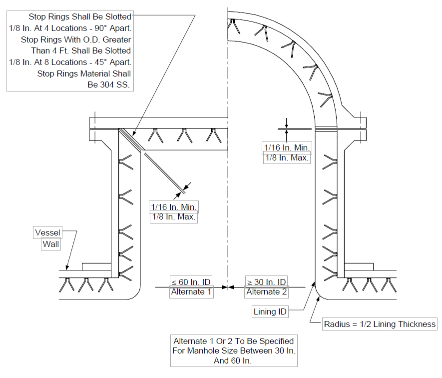
FIGURE 1B
LARGE DIAMETER, NO INTERNAL PIPING,
HOT EXTERNAL PIPING, HOT VESSEL, ABRASIVE SERVICE


Note 2
Note 1
NOTES:
- For hexmesh termination detail, see Figure 10.
- For corner detail, see Figure 10.
FIGURE 1C
LARGE DIAMETER, NO INTERNAL PIPING,
HOT EXTERNAL PIPING, COLD VESSEL, NON-ABRASIVE SERVICE
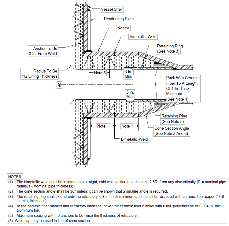
FIGURE 1D
LARGE DIAMETER, NO INTERNAL PIPING, COLD EXTERNAL PIPING, COLD VESSEL, NON-ABRASIVE OR SINGLE COMPONENT ABRASIVE SERVICE
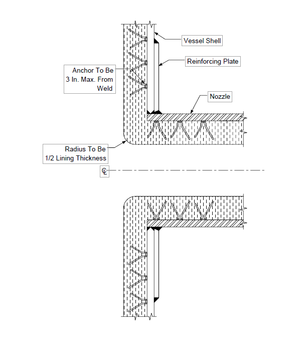
FIGURE 1E
LARGE DIAMETER, INTERNAL PIPING,
HOT EXTERNAL PIPING, HOT VESSEL, ABRASIVE SERVICE
FIGURE 1F
LARGE DIAMETER, INTERNAL PIPING,
HOT EXTERNAL PIPING, COLD VESSEL, NON-ABRASIVE SERVICE
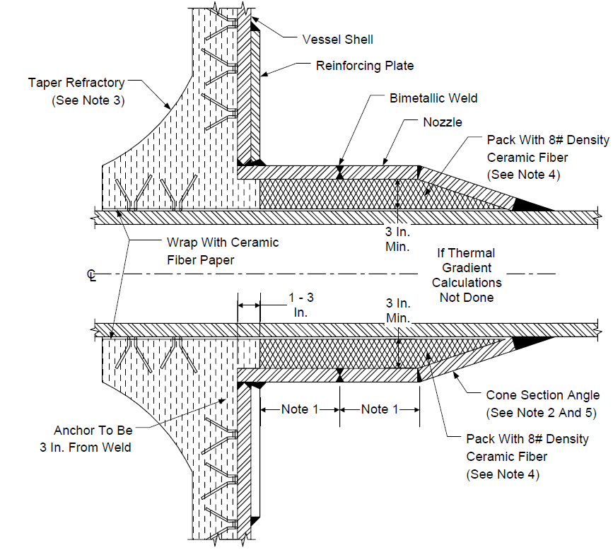
NOTES:
- The bimetallic weld shall be located on a straight, cold wall section at a distance 2.5Rt from any discontinuity (R = nominal pipe radius, t = nominal pipe thickness).
- The cone section angle shall be 30° unless it can be shown that a smaller angle is required.
- The distance which the insulative refractory lining extends inside the vessel shall be determined by a detailed thermal stress analysis. The internal refractory (taper to shell) design requires review and approval by owner's engineer and should be specified based on thermal gradient calculations.
- At the ceramic fiber blanket and refractory interface, cover the ceramic fiber blanket with 6 mil. polyethylene or 0.004 in. thick aluminum foil.
- Weld cap may be used in lieu of cone section.
FIGURE 1G
LARGE DIAMETER, INTERNAL PIPING,
HOT EXTERNAL PIPING, COLD VESSEL, ABRASIVE SERVICE
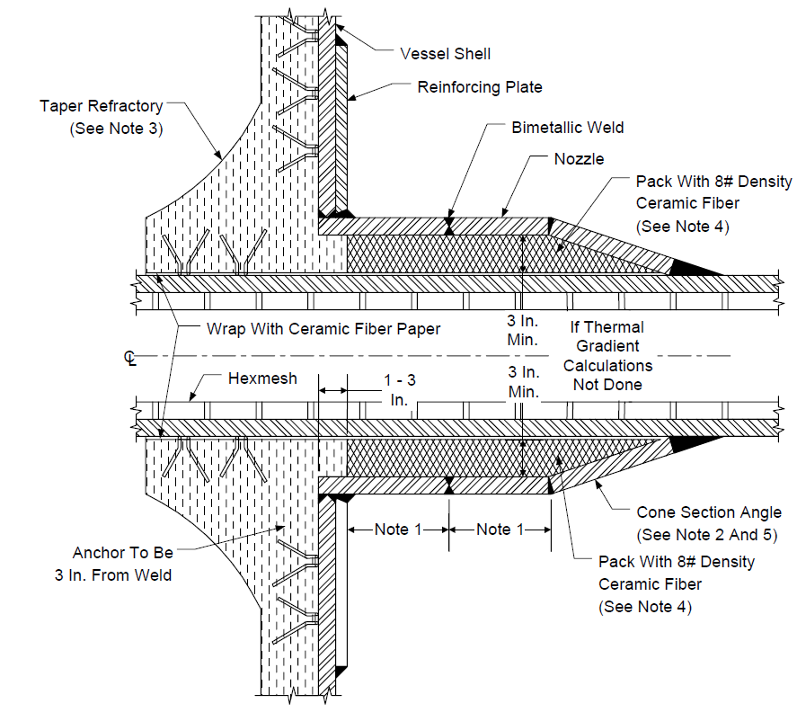
NOTES:
- The bimetallic weld shall be located on a straight, cold wall section at a distance 2.5 Rt from any discontinuity (R = nominal pipe radius, t = nominal pipe thickness).
- The cone section angle shall be 30° unless it can be shown that a smaller angle is required.
- The distance which the insulative refractory lining extends inside the vessel shall be determined by a detailed thermal stress analysis. The internal refractory (taper to shell) design requires review and approval by owner's engineer and should be specified based on thermal gradient calculations.
- At the ceramic fiber blanket and refractory interface, cover the ceramic fiber blanket with 6 mil. polyethylene or 0.004 in. thick aluminum foil.
- Weld cap may be used in lieu of cone section.
FIGURE 1H
LARGE DIAMETER, INTERNAL PIPING, COLD EXTERNAL PIPING, COLD VESSEL, NON- ABRASIVE SERVICE
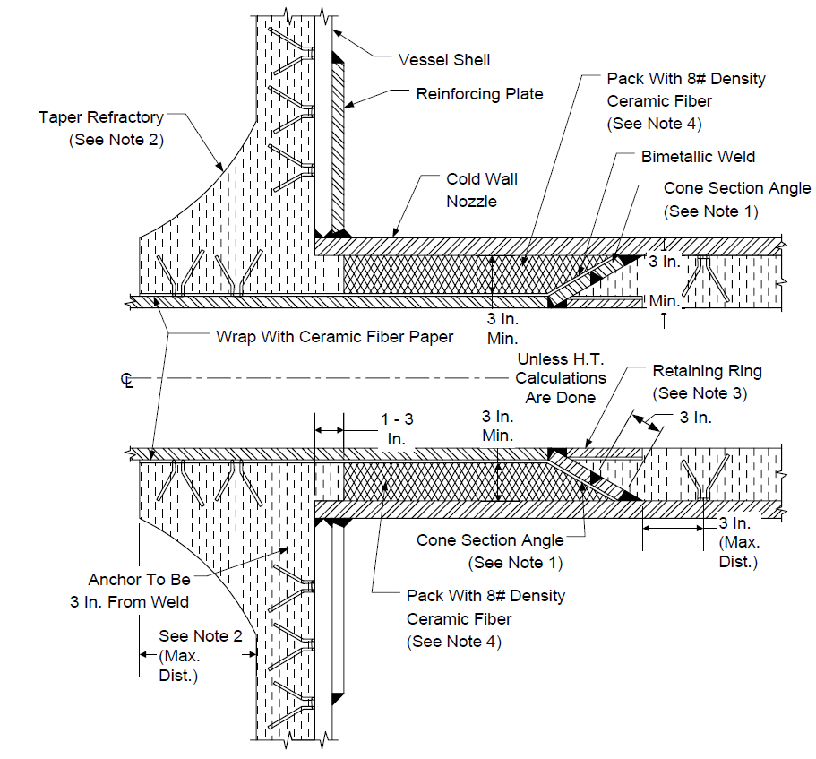
NOTES:
- The cone section angle shall be 30° unless it can be shown that a smaller angle is required.
- The distance which the insulative refractory lining extends inside the vessel shall be determined by a detailed thermal stress analysis. The internal refractory (taper to shell) design requires review and approval by owner's engineer and should be specified based on thermal gradient calculations.
- The retaining ring shall extend until the refractory is 3 in. thick minimum and it shall be wrapped with ceramic fiber paper (1/16 in. min. thickness).
- At the ceramic fiber blanket and refractory interface cover the ceramic fiber blanket with 6 mil. polyethylene or 0.004 in. thick aluminum foil.
FIGURE 1I
LARGE DIAMETER, INTERNAL PIPING,
COLD EXTERNAL PIPING, COLD VESSEL, ABRASIVE SERVICE
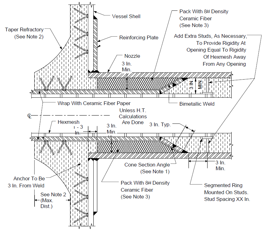
NOTES:
- The cone section angle shall be 30° unless it can be shown that a smaller angle is required.
- The distance which the insulative refractory lining extends inside the vessel shall be determined by a detailed thermal stress analysis. The internal refractory (taper to shell) design requires review and approval by owner's engineer and should be specified based on thermal gradient calculations.
- At the ceramic fiber blanket and refractory interface cover the ceramic fiber blanket with 6 mil. polyethylene or 0.004 in. thick aluminum foil.
FIGURE 2A "SINGLE LAYER" LININGS
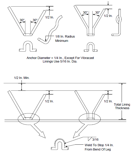
FIGURE 2B
STUDS AND ANCHORS FOR DUAL LAYER LINING
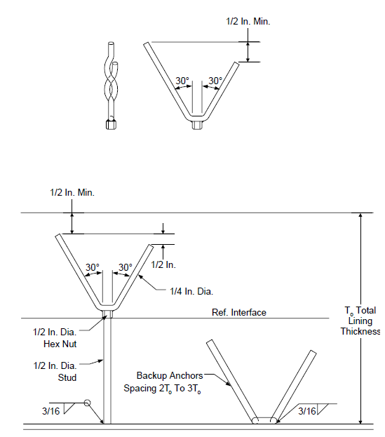
FIGURE 3
ANCHOR PATTERNS FOR SINGLE LAYER LININGS
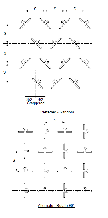
FIGURE 4A REQUIRED HEXMESH TYPE
Hexmesh To Be Lance Type
FIGURE 4B
STUD AND WASHER JOINTS FOR DUAL LAYER LINING USING HEXMESH8
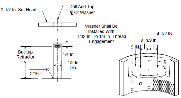
FIGURE 5A
HEXMESH DETAILS AT LINED NOZZLES
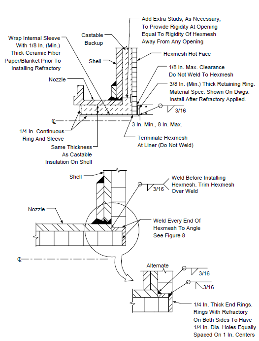
FIGURE 5B
HEXMESH DETAILS AT UNLINED NOZZLES
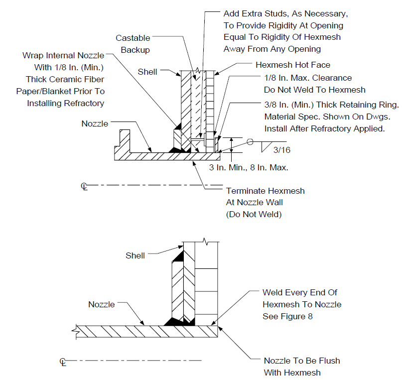
FIGURE 6A
S-BAR ANCHORS
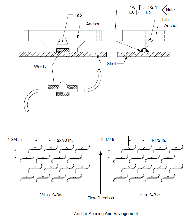
FIGURE 6B CURL ANCHORS
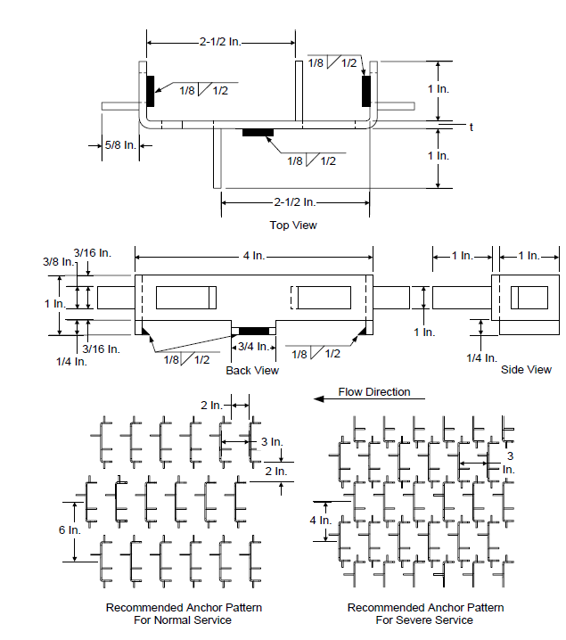
FIGURE 7A
Weld Details for Anchors
FIGURE 7B
Weld Details for Anchors
FIGURE 8A
IRREGULAR SHAPED PANEL JOINTS
FIGURE 8B ALIGNED, UNCUT JOINTS
FIGURE 8C UNALIGNED, UNCUT JOINTS
FIGURE 8D ALIGNED, CUT JOINTS
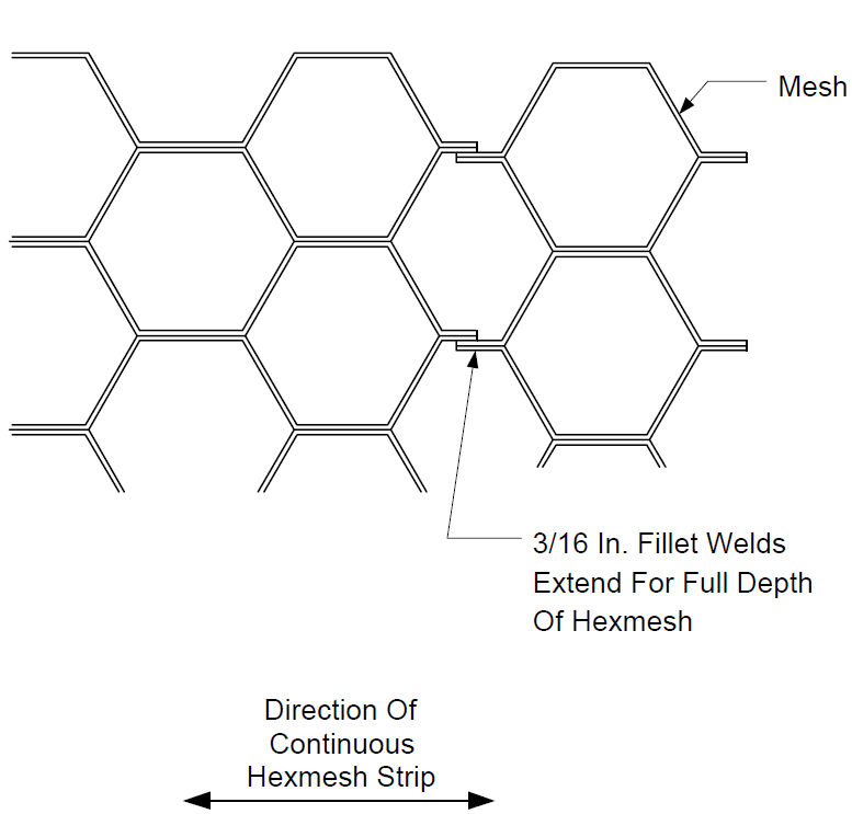
FIGURE 8E UNALIGNED, CUT JOINTS
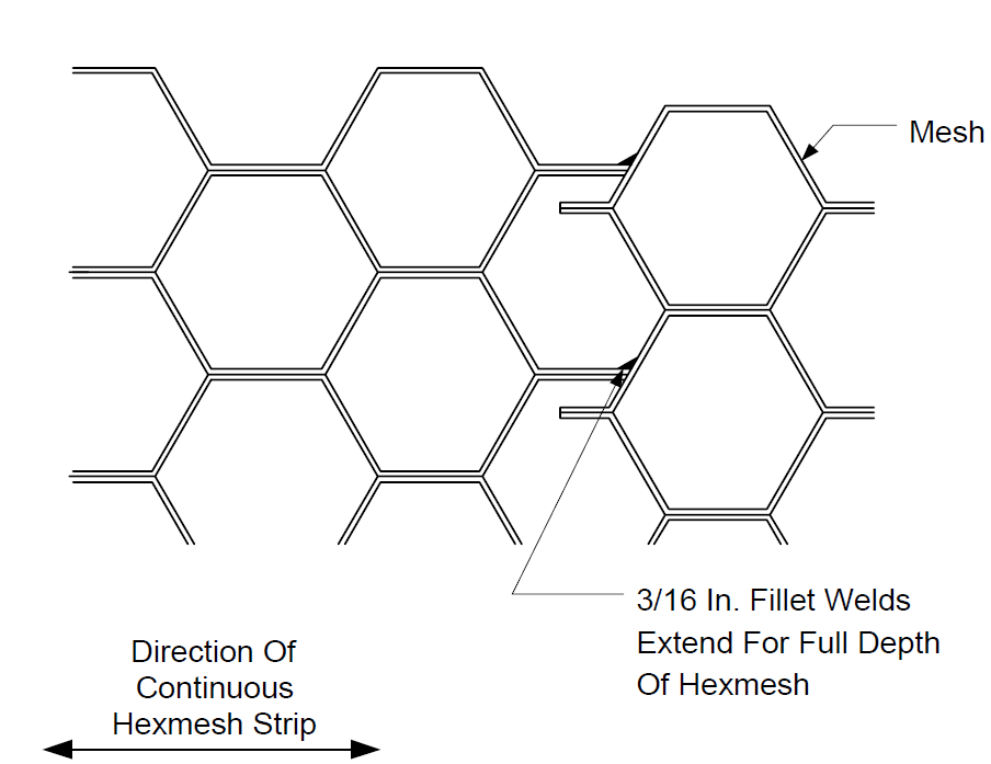
FIGURE 8F
JOINT OF HEXMESH TO END RINGS
.
FIGURE 9
REQUIRED HEXMESH DETAILS AT FIELD WELDED ENDS
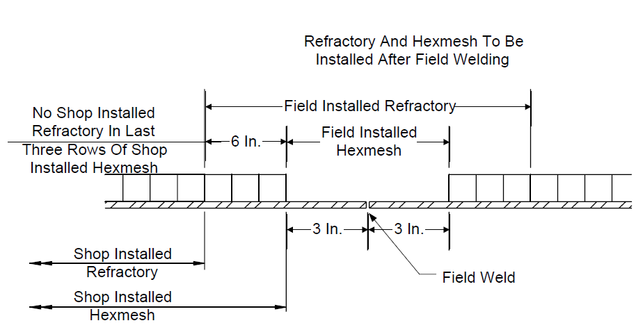
FIGURE 10
DETAILS AT HEXMESH TERMINATIONS
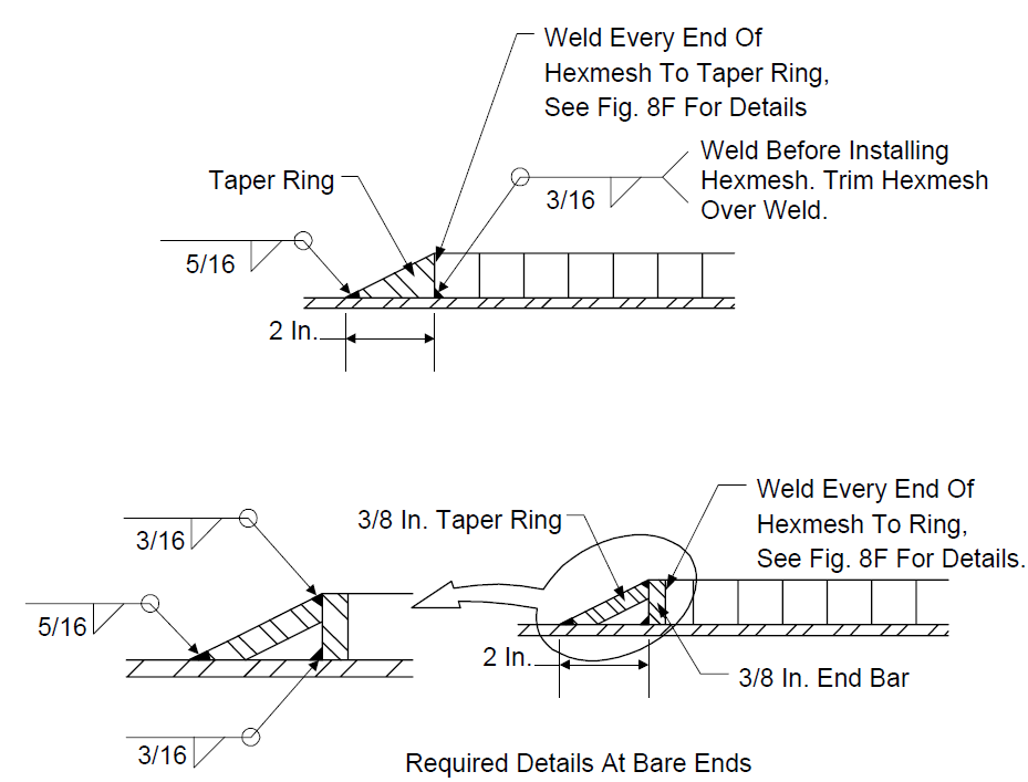
FIGURE 10 (CONTINUED) DETAILS AT HEXMESH TERMINATIONS
REQUIRED DETAILS AT INSIDE CORNERS
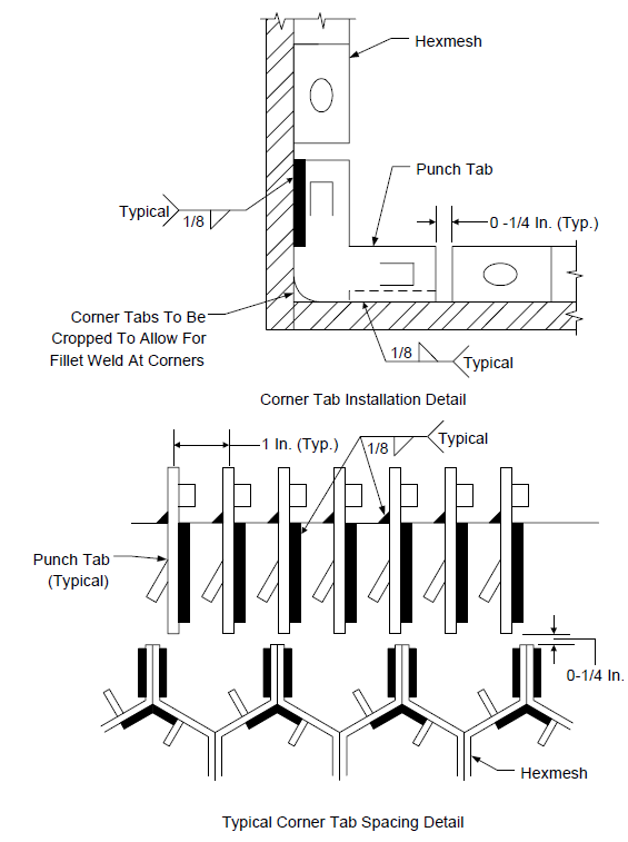
FIGURE 11
CASTABLE FIELD JOINTS MAKE-UP DETAILS
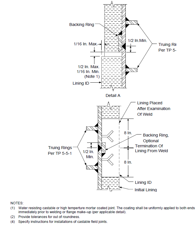
FIGURE 12
REPAIR OF CASTABLE LININGS
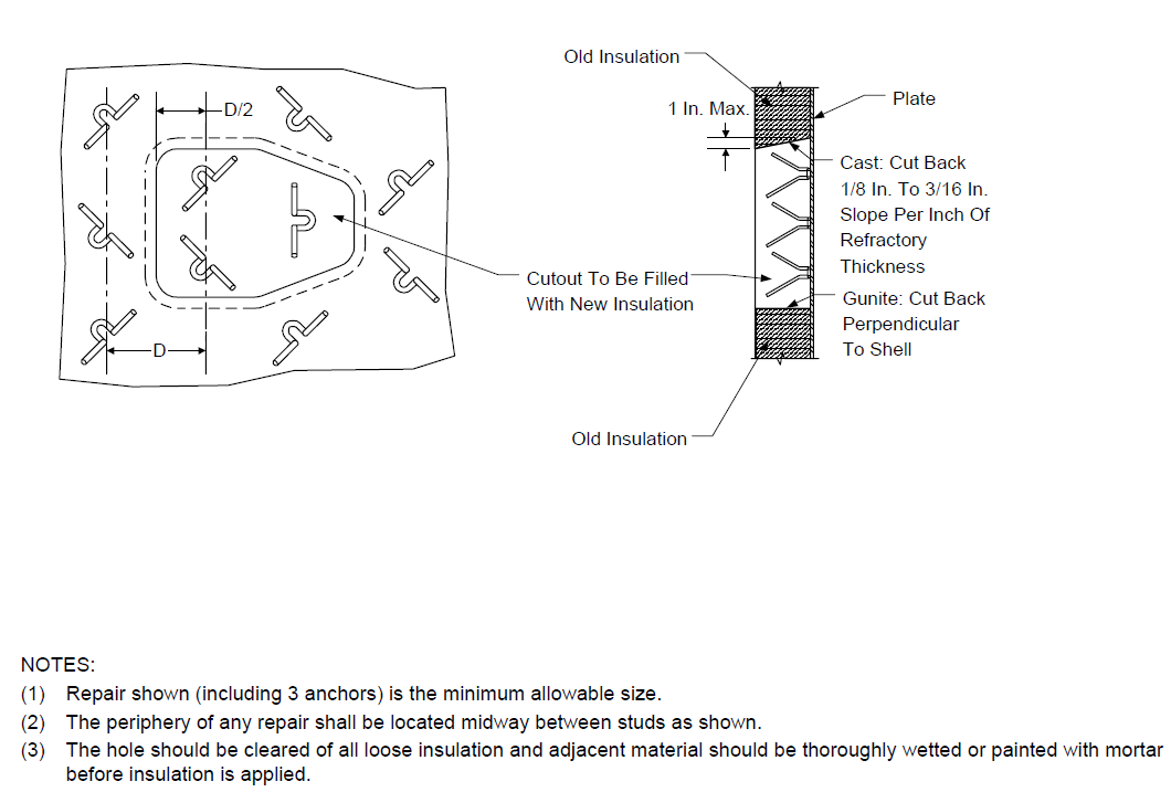
FIGURE 13 TRANSITION SECTION DETAILS
(FIELD WELD AND INSTALLATION)
© 2026 Inflection Point Engineering, LLC. All rights reserved. The content of this page — including calculation methods, reference data, written analysis, interactive tools, and source code — is the intellectual property of Inflection Point Engineering, LLC and is protected under applicable copyright, trademark, and trade secret laws. Unauthorized reproduction, redistribution, modification, or derivative use in whole or in part is prohibited without prior written consent.
Disclaimer. This material is provided for informational and educational purposes only and does not constitute professional engineering advice. Calculations, reference data, and methodologies are based on published standards and accepted engineering practice but are not a substitute for engineering judgment, site-specific analysis, or review by a licensed Professional Engineer. Inflection Point Engineering, LLC makes no warranties, express or implied, regarding the accuracy, completeness, or fitness for a particular purpose of any content presented here, and shall not be liable for any direct, indirect, incidental, or consequential damages arising from its use. Users assume all risk associated with applying this content to real-world design, operations, or decisions.
© 2026 Inflection Point Engineering, LLC. All rights reserved.