 Section 10 — Material Requirements
Cathodic Protection for Tank Bottoms
IPE Engineering Practice IPE-EP-10-3-6
Document number: IPE-EP-10-3-6 · Section: 10 — Material Requirements
SCOPE
- This Practice provides guidance for cathodic protection mitigation of underside corrosion problems of aboveground storage tanks.
- The specific cathodic protection systems presented in this Practice are recommended in the event that a need for a cathodic protection system is recognized by the individual refinery or required by this Practice.
- An asterisk (*) indicates that a decision by the Owner or Owner’s Engineer is required, or that additional information is to be furnished by the Purchaser.
- Any deviation from this Practice must be approved by the procedure described in EP 1–1–3.
2.0 REFERENCES
The latest edition of the following standards and publications are ref erred to herein.
STANDARDS AND PUBLICATIONS
| Engineering Practices |
|---|
| EP 1–1–3 Deviations to Engineering Practices |
| NACE |
| RP0169–83 Control of External Corrosion on Underground or Submerged Metallic Piping Systems RP0177–83 Mitigation of Alternating Current and Lightning Effects on Metallic Structures and Corrosion Control of Systems RP0285–85 Control of External Corrosion of Metallic Buried, Partially Buried, or Submerged Liquid Storage Systems RP0572–85 Design, Installation, Operation and Maintenance of Impressed Current Deep Groundbeds |
| API |
| STD 620 Design and Construction of Large, Welded Low Pressure Storage Tanks STD 650 Welded Steel Tanks for Oil Storage STD 653 Tank Inspection and Repair RP 651 Cathodic Protection for Above–Ground Storage Tanks |
| ASTM |
| G–57 Method for Field Measurement of Soil Resistivity Using the Wenner Four– Electrode Method |
DEFINITIONS
- Anode – An electrode that is characterized by electron loss (oxidation). Antonym: cathode.
- Backfill – Low resistivity material (usually carbonaceous) used to surround groundbed anodes. Functions to increase the effective size of the anode, which results in a reduction of resistance to earth and to bear the brunt of consumption resulting from current discharge.
- Cathodic Protection – A technique to prevent corrosion of a metal surface by making it cathodic to its environment.
- Continuity Bond – A metallic connection that provides electrical continuity.
- Contractor – Company or business that agrees to furnish materials or perform specified services at a specified price and/or rate to the Owner.
- Corrosion – Deterioration of a metal by its chemical reaction with a non–metal.
- Current Density – The current per unit area.
- Electrode Potential – The potential of an electrode as measured against a reference electrode. The electrode potential does not include any loss of potential in the solution due to current passing to or from the electrodes, i.e., it represents the reversible work required to move a unit charge from the electrode surface through the solution to the reference electrode.
- Electrolyte – A chemical substance or mixture, usually liquid, containing ions that migrate in an electric field. For the purpose of this Practice, electrolyte refers to the soil or liquid adjacent to and in contact with a buried or submerged metallic structure, including the moisture and other chemical contained therein.
- Foreign Structure – Any structure that is not intended as a part of the system of interests.
- Galvanic Anode – A metal that, because of its relative position in the galvanic series, provides sacrificial protection to metal or metals that are more noble in the series, when coupled in an electrolyte. These anodes are the current source in one type of cathodic protection.
- Galvanic Series – A list of metals and alloys arranged according to their relative potentials in a given environment.
- Impressed Current – Direct current supplied by a power source external to the electrode system.
- IR Drop – The voltage across a resistance in accordance with Ohm’s Law.
- Manufacturer – The recipient of a direct or indirect purchase order for materials and/or equipment. In this context, a direct order is one issued to a Manufacturer by a Contractor or the Owner. An indirect order is one issued to a Manufacturer by a vendor (recipient of a direct order) for materials, fabricated components, or subassemblies.
- Owner – Refining Company.
- Owner’s Engineer – A Refining Company appointed engineer.
- Purchaser – The party placing a direct purchase order. The Purchaser is the Owner’s designated representative.
- Rectifier – A device for converting alternating current to direct current.
- Reference Electrode – A device whose open circuit potential is constant under similar conditions of measurement.
- Retrofitted Double Bottom Above–Ground Storage Tanks – An above–ground storage tank with a second bottom installed through a slot in the shell several inches above the original bottom with various media, often sand, between the two bottoms. Leak detection, release prevention, and possibly cathodic protection systems are installed between the bottoms.
- Sacrificial Protection – Reduction or prevention of corrosion of a metal in an electrolyte by galvanically coupling it to a more anodic metal.
- Secondary Containment – A device or system used to control the accidental escape of a stored product for later proper removal or recovery.
- Shunt – A conductor of known electrical resistance through which current flow may be determined by measuring the voltage drop across it.
- Stray Current – Current flowing through paths other than the intended circuit.
- Structure–to–Electrode Voltage – (Also Structure–to–Soil Potential or Pipe–to–Soil Potential). The voltage difference between a buried metallic structure and the electrolyte that is measured with reference to an electrode in contact with the electrolyte.
- Voltage – An electromotive force or a difference in electrode potentials expressed in volts.
DETERMINATION OF NEED FOR CATHODIC PROTECTION
- All aboveground tanks shall be evaluated as their need for cathodic protection. Corrosion surveys, operating records, and national, state and local code requirements should be used in the above evaluation. It shall be recognized that external cathodic protection will have no effect on internal tank corrosion. Guidelines to help determine the need for cathodic protection are as follows:
- (*) Existing tanks being retrofitted with some mode of release prevention shall have a cathodic protection system installed, unless otherwise specified by the Owner’s Engineer.
- New aboveground storage tanks should be analyzed as to their need for cathodic protection. If cathodic protection is deemed necessary, provisions for its design, installation, maintenance, and an annual survey of its performance per API RP 651 Section 9 must be made during the initial design of the tank.
- If cathodic protection is deemed necessary, an economic analysis shall be performed to determine whether an impressed current or sacrificial anode system shall be used.
- Soil conditions shall be considered when determining a need for cathodic protection. In particular, soil pH, chloride content, sulfate content, and resistivity should be known. See Table 1 and Table 2 for the effect of these variables on corrosion rate to steel.
- Other factors that shall be considered when determining the need for cathodic protection system are contained in API RP 651 Section 3.
- ADVANTAGES AND DISADVANTAGES OF IMPRESSED CURRENT AND SACRIFICIAL ANODE CATHODIC PROTECTION SYSTEMS
- Impressed Current
- Advantages
- Availability of large driving potential
- High current output current capable of protecting large structures
- Applicable to almost any soil resistivity
- Longer life
- Disadvantages
- Can create stray current corrosion problems on foreign structures
- Protection is dependent on electrical power
- Higher maintenance and operating cost
- Higher capital cost for small installations
- Requires more frequent monitoring
- Sacrificial Anode
- Advantages
- No power supply required
- Little worry about stray current problems
- Low maintenance costs
- Lower costs for small diameter tanks
- Disadvantages
- Driving potential is fixed for a particular type of anode.
- Low current output
- Limited applicability in high resistivity soils
- Limited size of structure which can be properly protected
(*) ACCEPTABLE CATHODIC PROTECTION SYSTEM DESIGNS
All cathodic protection systems must receive final approval by the Owner’s Engineer. However, the following cathodic protection systems are presented as guidelines that follow current cathodic protection industry practice. All systems shall meet one of NACE RP 0169–83 criteria for effectiveness.
- (*) Double Bottom Tank Retrofits with Cathodic Protection Systems
For tanks retrofitted with double bottoms, a cathodic protection system shall be installed in the sand material between the bottoms above release prevention liner, unless the otherwise specified by the Owner’s Engineer.
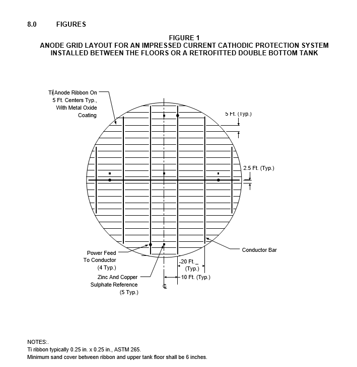
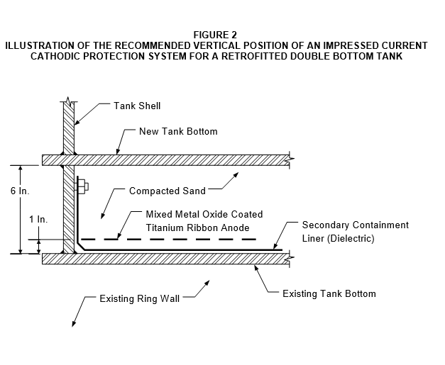
- Details for an impressed current cathodic protection system installed between the bottoms of a retrofitted tank are shown in Figure 1 and Figure 2. Current information suggests that this anode grid should be installed approximately 1 inch above the liner.
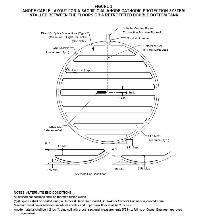
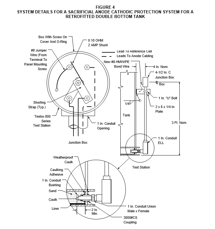
- Details for a sacrificial anode cathodic protection system installed between the bottoms of a retrofitted tank are shown in Figure 3 and Figure 4.
- When required by the Owner’s Engineer, a plastic grid shall be placed above the anode material to electrically isolate the anode and primary tank bottom. A minimum of 2” compacted sand shall separate the plastic grid from the primary tank bottom.
- Retrofitting Tanks with Cathodic Protection Systems
Cathodic protection systems may be added to existing tanks not undergoing a tank lift or a double bottom retrofit via one of the following methods.
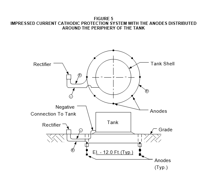
- Horizontal or vertical anodes distributed at the periphery of the tank, see Figure 5.
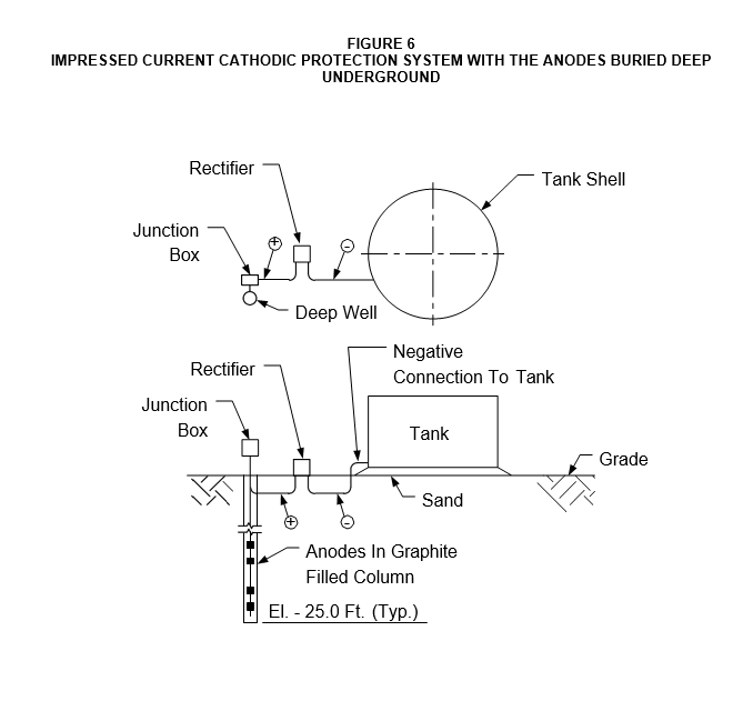
- A deep anode system, see Figure 6.
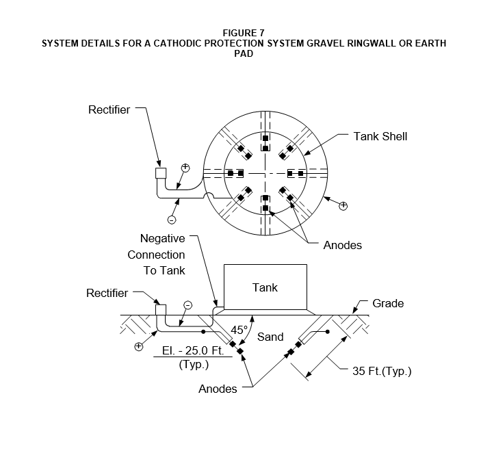
- Angle drilled anode systems extending under the tank bottom, see Figure 7.
- For #1–3 above, it is recommended that perforated PVC pipe be bored under the tank for reference electrode access. Structure–to–soil potential survey measurements taken at points outside the circumference of the tank do not provide accurate indications as to effectiveness of the cathodic protection system due to IR drop. Locating a reference electrode directly under the center of the tank bottom will minimize these voltage drops.
- Methods 2 and 3 above have the advantage of providing better protection to the center of the tank floor.
- New Construction
- For new construction, cathodic protection systems may be installed (a determination should be made as in Section 4.0 of this Practice) and should be essentially identical to those presented for double bottom retrofit tanks in Figures 1, Figure 3, Figure 4 and paragraph
6.1 above (without the double bottom).
- The use of liners beneath the tank bottom as secondary containment and as a means of leak detection thwarts any attempt at effective use of cathodic protection by deep anodes.
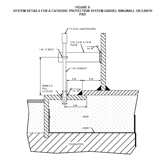
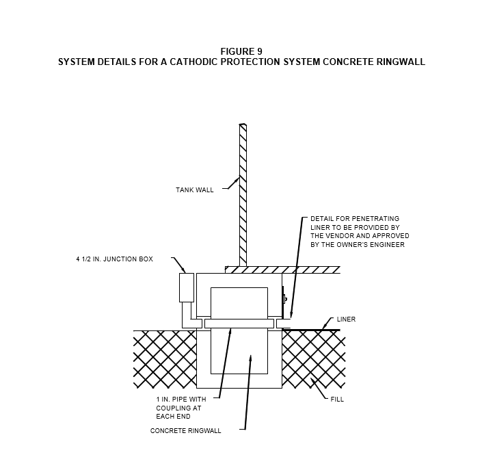
- Details of cathodic protection systems for the cases of a) gravel ringwall or earth pad, or b) concrete ringwall are shown in Figure 8 and Figure 9 respectively.
7.0 TABLES
TABLE 1
EFFECT OF RESISTIVITY ON THE CORROSIVITY OF SOIL
| Resistivity Range, OHM–CM | Potential Corrosion Activity |
|---|---|
| < 500 | Very Corrosive |
| 500 – 1,000 | Corrosive |
| 1,000 – 2,000 | Moderately Corrosive |
| 2,000 – 10,000 | Mildly Corrosive |
| > 10,000 | Progressively Less Corrosive |
TABLE 2
EFFECT OF SEVERAL CHEMICAL CONSTITUENTS ON THE CORROSIVITY OF SOIL
| Constituent | Corrosive | Very Corrosive |
|---|---|---|
| pH | Chlorides | Sulfates |
| 5.0 – 6.5 | 300 – 1000 ppm | 1000 – 5000 ppm |
| < 5.0 | > 1000 ppm | > 5000 ppm. |
© 2026 Inflection Point Engineering, LLC. All rights reserved. The content of this page — including calculation methods, reference data, written analysis, interactive tools, and source code — is the intellectual property of Inflection Point Engineering, LLC and is protected under applicable copyright, trademark, and trade secret laws. Unauthorized reproduction, redistribution, modification, or derivative use in whole or in part is prohibited without prior written consent.
Disclaimer. This material is provided for informational and educational purposes only and does not constitute professional engineering advice. Calculations, reference data, and methodologies are based on published standards and accepted engineering practice but are not a substitute for engineering judgment, site-specific analysis, or review by a licensed Professional Engineer. Inflection Point Engineering, LLC makes no warranties, express or implied, regarding the accuracy, completeness, or fitness for a particular purpose of any content presented here, and shall not be liable for any direct, indirect, incidental, or consequential damages arising from its use. Users assume all risk associated with applying this content to real-world design, operations, or decisions.
© 2026 Inflection Point Engineering, LLC. All rights reserved.