 Section 10 — Material Requirements
Statically Cast Steel and Alloy Return Bends and
IPE Engineering Practice IPE-EP-10-2-4
Document number: IPE-EP-10-2-4 · Section: 10 — Material Requirements
SCOPE
- This Practice covers requirements governing the materials, fabrication, and testing of statically cast steel and alloy return bends and load bearing (tube supports) parts for fired heaters for use in high temperature or corrosive service, or both.
- This Practice excludes centrifugally cast furnace tubes and castings for other components such as valves and pump casings.
- Any deviation from this Practice must be approved by the procedure described in EP 1–1–3.
- An asterisk (*) indicates that a decision by the Owner’s Engineer or Owner is required or that additional information is furnished by the Purchaser.
- A revision bar indicates all changes made to this Revision.
2.0 REFERENCES
The latest edition of the following standards and publications are referred to herein.
STANDARDS AND PUBLICATIONS
| Engineering Practices |
|---|
| EP 1–1–3 Deviations to Engineering Practices EP 8–2–1 Fired Heaters EP 15–1–4 Positive Materials Identification (PMI) |
| API Publications |
| Std 560 Fired Heaters For General Refinery Services |
| ASME Codes |
| Sec V Nondestructive Examination Sec VIII Pressure Vessels, Division 1 Sec IX Welding Qualifications |
| ASME/ANSI Standard |
| B16.5 Pipe Flanges and Flanged Fittings |
| ASTM Standards |
| E186 Reference Radiographs for Heavy–Walled (2 to 4–1/2 in.) Steel Castings E280 Heavy Wall (4–1/2 in. to 12 in.) Castings E446 Reference Radiographs for Steel Castings up to 2 in. in Thickness |
| MSS Specification |
| SP–55 Quality Standard for Steel Castings for Valves, Flanges, and Fittings and Other Piping Components (Visual Method) |
DEFINITIONS
- Critical Areas of Load Bearing Castings – Areas with sharp changes in casting cross–section, areas subject to stress during service, weld bevels, and any other areas defined by the Owner’s Engineer.
- Inspector – A Refining Company appointed engineer or inspector.
- Manufacturer – The recipient of a direct or indirect purchase order for materials and/or equipment. In this context, a direct order is one issued to a Manufacturer by a Contractor or the Owner. An indirect order is one issued to a Manufacturer by a vendor (recipient of a direct order) for materials, fabricated components, or subassemblies.
- Non–critical Areas of Load Bearing Castings – Areas not considered to be critical from a stress, service, or fabrication standpoint.
- Owner – Refining Company.
- Owner’s Engineer – A Refining Company appointed engineer.
- Purchase Order – The contractual document given to the Manufacturer to authorize a purchase.
- Purchaser – The party placing a direct purchase order. The Purchaser is the Owner’s designated representative.
- Quality Control Plan – The Manufacturer’s job specific documented plan for ensuring that all specified technical requirements will be followed. The Quality Control Plan shall include, as a minimum, the following; fabrication schedule including all heat treatment requirements, forming and rolling procedures, and an inspection and test plan with a schedule identifying all inspection points required by the Owner.
- Quality Control System – The Manufacturer’s documented system for ensuring that all applicable code requirements for the manufacturing process including material handling and identification, design, fabrication, inspection and testing are followed.
QUALITY CONTROL
- (*) The Manufacturer shall operate a Quality Control System to ensure that the technical requirements of the pressure vessel code specified by the Owner’s Engineer are achieved. The Owner’s Engineer may require demonstration of the Quality Control System, but this may be waived if the system has been verified recently by an accreditation scheme acceptable to the Owner’s Engineer.
- The Manufacturer shall submit a Quality Control Plan which shall be reviewed and approved by the Inspector.
- (*) Unless otherwise specified by the Owner’s Engineer, a copy of the quality control plan signed by all inspection parties shall be submitted to the Owner’s Engineer for approval prior to the start of fabrication.
- The Manufacturer shall ensure that technical and qualify assurance requirements specified in the Purchase Order are applied to all materials, equipment and services provided by sub– vendors and to any free–issue materials.
DOCUMENTATION
- All mechanical design calculations required to demonstrate compliance to this Practice shall be provided by the Manufacturer (or Owner’s Engineer, if applicable) for each component. The English units of measurement shall be used for all calculations and fabrication drawings. Design calculations made with the use of computer programs must either be accompanied by appropriate program documentation or substantiated by detailed hand calculations.
- (*) After Owner’s Engineer approval and final revision, approved fabrication drawings shall be furnished by the Manufacturer to the Owner’s Engineer. Fabrication drawings with proprietary clauses are unacceptable.
- (*) Welding and weld repair procedures, and joint preparation details, shall be submitted to the Purchaser for approval by the Owner’s Engineer.
- A report on the analysis of each heat shall be supplied by the foundry to the Inspector. This report shall include, in addition to the elements specified, the results of analysis for residual or tramp elements normally included in the foundry’s quality control procedures.
- (*) The number of copies of documentation required by this Practice will be specified by the Purchaser.
MATERIALS
- (*) Material selection shall be in accordance with EP 8–2–1. Only foundry sources approved by the Owner’s Engineer shall be used for supplying castings.
- Material composition and mechanical properties shall conform to the specified standard or specification except that the lead content shall not exceed 0.01%. Where statically cast fittings are to be used in conjunction with centrifugally cast tubes the nominal composition of the fittings shall match that of the tubes.
- (*) If patented or proprietary alloys are specified, the composition of such alloys shall be approved by the Owner’s Engineer. Fittings shall be specified “shell molded”, provided configuration and size permit.
- Chaplets, chills and internal chills shall be of the same nominal chemical composition as the castings.
DESIGN
- The design of statically cast pressure containing parts shall be in accordance with the requirements of this Practice. All pressure containing parts shall be designed for an internal pressure of not less than 10% above the maximum operating pressure. The design temperature shall not be less than the maximum operating temperature of the contained fluid plus 25ºF. The minimum design metal temperature shall be established in accordance with the ASME Code, Section VIII, Division 1.
- The design of load bearing members (tube supports) for fired heaters shall be in accordance with API 560 and the additional requirements of this Practice. Design conditions, support layout and arrangement, and support details for load bearing members shall be in accordance with EP 8–2–1 and API 560.
- The allowable stress values and the casting quality factor to be used for all components shall be as follows:
- (*) Statically Cast Pressure Containing Parts – The allowable stress values shall be in accordance with the dead load values listed for tube supports in EP 8–2–1. A casting quality factor of 0.8 shall be applied to these allowable stress values. A casting quality factor of 1.0 may be used if the examination requirements and acceptance criteria of the ASME Code, Section VIII, Division 1, Appendix 7, are implemented, and if approved by the Owner’s Engineer.
- Load Bearing Members (Tube Supports) – The allowable stress values shall be in accordance with EP 8–2–1. A casting quality factor of 0.8 shall be used.
FABRICATION
- (*) Base metal weldability tests are required for all materials not listed in ASME Code Section
IX. Weldability tests shall be approved by the Owner’s Engineer.
- Welding procedure (including repairs) and performance qualification for each cast alloy shall be in accordance with ASME Code Section IX.
- (*) Weld bevels on ends of fittings shall be machined to remove unacceptable surface discontinuities. Other machining shall meet the specified dimensions and tolerances.
INSPECTION PROCEDURES AND ACCEPTANCE CRITERIA
- (*) The Manufacturer shall furnish copies of the casting drawings to the Inspector. These drawings shall have been previously approved by the Owner’s Engineer and shall show all casting details, including tolerances and minimum allowable wall thicknesses.
- (*) The Manufacturer shall furnish copies of all nondestructive testing and inspection procedures to the Inspector. These procedures shall have been previously approved by the Owner’s Engineer and shall include all details of radiographic, ultrasonic, magnetic particle, liquid penetrant, and visual inspections.
- The Inspector shall be given at least five days notice to arrange for witnessing of inspection.
- (*) Mechanical testing shall be performed on prolongations of representative size, subsequent to all heat treatments, unless otherwise agreed upon prior to the pouring of the castings. Prolongations shall be removed after material heat treatment (normalizing, quenching, tempering, etc.). Testing samples shall then be given a simulated heat treatment to represent any further heat treatments that the production casting may require (for example, repair postweld heat treatment). Simulated PWHT soaking times shall be at least twice that required for a single postweld heat treatment.
- Prior to acceptance of any castings, the Inspector shall review and approve the complete casting documentation package. This documentation package shall contain the Certified Material Test Report (CMTR) for each heat of material, casting weld repair maps, casting inspection reports, and the approved welding, heat treatment, and nondestructive testing procedures. The CMTR shall contain the chemical analysis of the material, the mechanical test data (including impact testing if required by the applicable materials specification), and the heat treatment cycle applied to the material.
- The Manufacturer shall demonstrate the capability of the foundry to produce sound castings Such evidence shall consist of:
- Documentation attesting to the compliance with governing specifications for the chemical and physical properties of the materials.
- The satisfactory results of examinations to the criteria of this Basic Practice as witnessed by the Inspector.
INSPECTION REQUIREMENTS FOR CASTINGS
- Load bearing and pressure containing castings shall be inspected in accordance with the requirements in Table 1.
- Radiographic acceptance criteria for castings shall be as stipulated in Table 2.
- If a defective casting is found, another casting from the same pattern or heat shall be examined. If this examination reveals additional defects, all remaining castings to the particular pattern or heat shall be radiographed.
- Requirements for positive material identification are per EP 15–1–4.
PNEUMATIC AND HYDROSTATIC TESTING OF PRESSURE CONTAINING CASTINGS
- Castings for pressure service shall be tested per the applicable ASTM Specification. In addition, each casting shall be air tested by the foundry using a soap suds solution applied to the entire outside surface. The test pressure shall be at least 75 psig. Tests shall be maintained for a sufficient period of time to permit the Inspector to examine the part under pressure, with a minimum period of 15 minutes.
- For castings not covered by the hydrostatic test requirements of ANSI B16.5, the hydrostatic test pressure shall be at least 200 psig or 1–1/2 times the design pressure, whichever is greater. The test pressure shall be maintained for at least 15 minutes.
- If the base metal has a specified minimum elongation of 6% or less, or if any cast component has been used in process service, the test pressure shall be held for 15 minutes and then reduced by 1/3, at which time the visual inspection should be conducted.
REPAIRS
- Procedures for repair and re–examination of castings shall be in accordance with the ASME Code, Section VIII, Appendix 7, and the additional requirements of this Practice.
- Cavities deeper than 1/8 inch, resulting from metal removal to investigate flaw depth, shall be repaired by welding, if the remaining metal thickness is less than the minimum specified.
- Welded repair of defects shall not proceed without approval by the Inspector.
- Acceptance criteria for welded repairs shall be based on the same criteria used for the original casting.
- If the depth of welded repair exceeds 20% of the wall thickness or 1 inch, whichever is less, or if the area of welded repair exceeds 10 square inches, the casting shall be heat treated after repair in accordance with the specified material standard or specification.
13.0 TABLES
TABLE 1
INSPECTION REQUIREMENTS FOR LOAD BEARING AND PRESSURE CONTAINING CASTINGS
| Type of Examinations | Type of Casting | Extent of Examination | Extent of Examination | Acceptance Criteria |
|---|---|---|---|---|
| Type of Examinations | (100% or Critical Areas as Indicated) |
Number of Castings to be Examined | ||
| Visual per MSS SP–55 | Load Bearing | 100% | All Castings | MSS SP 55 |
| Pressure Containing | 100% | All Castings | ||
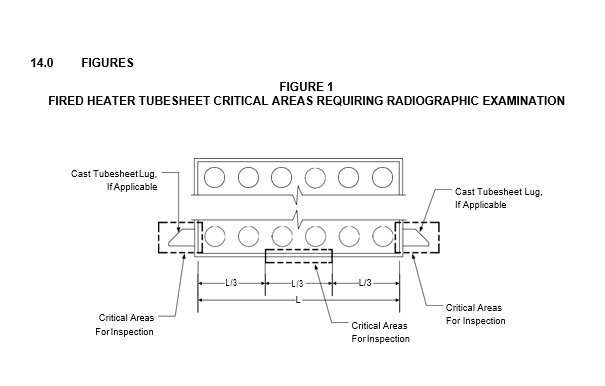
| Magnetic Particle per ASME Code Section V, Article z | Load Bearing: Fired Heater Tubesheets | Critical Areas Per Figure 1 | All Castings | ASME Code Section VIII, Appendix 7 Par. 7–2 (a) and Par. 7–3 (a)(2) and (3). |
| Load Bearing: All Other Components | Critical Areas only (1) | All castings other than those of austenitic and chromium–nickel materials | ||
| Pressure Containing | 100% | |||
| Liquid Penetrant per ASME Code Section V, Article 6 (2) | Load Bearing: Fired Heater Tubesheets | Critical Areas Per Figure 1 | All Castings | ASME Code Section VIII, Appendix 7 Par. 7–2 (b) and Par. 7–3 (a)(2) and (4).(3) |
| Load Bearing: All Other Components | Critical Areas only (1) | All castings of austenitic and chromium–nickel materials | ||
| Pressure Containing | 100% (internally to the extent practicable) |
TABLE 1
INSPECTION REQUIREMENTS FOR LOAD BEARING AND PRESSURE CONTAINING CASTINGS (CONTINUED)
| Type of Examinations | Type of Casting | Extent of Examination | Extent of Examination | Acceptance Criteria |
|---|---|---|---|---|
| Type of Examinations | (100% or Critical Areas as Indicated) |
Number of Castings to be Examined | ||
| Radiographic | Load Bearing: | Critical Areas | All Castings | In accordance with |
| per ASME Code | Fired Heater | per Figure 1 | paragraph 9.2 and | |
| Section V Article 3 (4), (5) | Tubesheets | Table 2 | ||
| Load Bearing: All Other Components | Critical Areas only (1) | Initial casting(s): first 2% of the order from each foundry for each pattern | ||
| Balance of castings: 4% of the order as selected by the Inspector | ||||
| Pressure Containing | 100%m | Initial casting(s): first 2% of the order from each foundry for each pattern or from each heat (6), (7) | ||
| Balance of castings: 15% of the order as selected by the Inspector |
NOTES:
- To be determined by the Inspector.
- For castings cleaned by blasting, the Manufacturer shall demonstrate, by use of a comparator block, that the technique employed does not close linear type flaws.
- Machined weld bevels and any counterbore shall be free of penetrant indications after single development.
- Fluorescent intensifying screens such as calcium tungstate shall not be used.
- For austenitic and chromium–nickel materials, only those castings passing liquid penetrant examination shall be radiographed.
- At least one casting for each pattern shall be fully radiographed, as selected by the inspector.
- For austenitic and chromium–nickel materials, at least one casting from each heat shall be fully radiographed.
TABLE 2
RADIOGRAPHIC ACCEPTANCE CRITERIA FOR CASTINGS
| Flaw Category | Acceptable Defect Severity Level | Acceptable Defect Severity Level | Acceptable Defect Severity Level |
|---|---|---|---|
| Flaw Category | ASTM E446 (Up to 2 inches) |
ASTM E186 (2 to 4–1/2 inches) |
ASTM 280 (4–1/2 to 12 inches) |
| Gas and Blowhole/Gas Porosity | 2 | 2 | 2 |
| Sand Spots and Inclusions/ Sand and Slag Inclusions | 4 | 3 | 3 |
| Internal Shrinkage/Shrinkage Type 1 Type 2 Type 3 Type 4 |
3 3 3 3 |
3 3 3 — |
3 3 3 — |
| Hot Tears/Linear Discontinuities | 0 | 0 | 0 |
| Cracks/Linear Discontinuities | 0 | 0 | 0 |
| Unfused Chaplets/Inserts | 0 | 0 | 0 |
| Internal Chills/Inserts | 0 | 0 | 0 |
© 2026 Inflection Point Engineering, LLC. All rights reserved. The content of this page — including calculation methods, reference data, written analysis, interactive tools, and source code — is the intellectual property of Inflection Point Engineering, LLC and is protected under applicable copyright, trademark, and trade secret laws. Unauthorized reproduction, redistribution, modification, or derivative use in whole or in part is prohibited without prior written consent.
Disclaimer. This material is provided for informational and educational purposes only and does not constitute professional engineering advice. Calculations, reference data, and methodologies are based on published standards and accepted engineering practice but are not a substitute for engineering judgment, site-specific analysis, or review by a licensed Professional Engineer. Inflection Point Engineering, LLC makes no warranties, express or implied, regarding the accuracy, completeness, or fitness for a particular purpose of any content presented here, and shall not be liable for any direct, indirect, incidental, or consequential damages arising from its use. Users assume all risk associated with applying this content to real-world design, operations, or decisions.
© 2026 Inflection Point Engineering, LLC. All rights reserved.