 Section 10 — Material Requirements
Unsaturate Gas Plants
IPE Engineering Practice IPE-EP-10-1-7
Document number: IPE-EP-10-1-7 · Section: 10 — Material Requirements
SCOPE
- This Practice provides information for the selection and use of materials in Unsaturate Gas Plants.
- This Practice is for guidance purposes and deviation per EP 1–1–3 is not required.
- An asterisk (*) indicates that a decision by the Owner or Owner’s Engineer is required, or that additional information is to be furnished by the Purchaser.
2.0 REFERENCES
The latest edition of the following standards and publications are referred to herein.
STANDARDS AND PUBLICATIONS
| Engineering Practices | Engineering Practices |
|---|---|
| EP 1–1–3 | Deviations to Engineering Practices |
| EP 5–1–1 | General Piping Design |
| EP 7–1–1 | Pressure Vessels |
| EP 7–2–1 | Pressure Vessel Internals |
| EP 9–1–1 | Atmospheric Storage Tanks |
| EP 9–2–1 | Low Pressure Storage Tanks |
| EP 9–4–1 | Pressure Storage Spheres |
| EP 10–2–1 | Material Requirements for Aggressive Environmental Services |
| EP 10–2–3 | Material Hardness Requirements |
DEFINITIONS
- Aggressive Environmental Service (AES) – Process services which result in material degradation such as cracking, scaling, blistering, and severe pitting and/or corrosion. Examples of such services are hydrogen service, wet hydrogen sulfide, cyanides, caustic, amine, and hydrofluoric acid. AES process fluid are defined in EP 10–2–1.
- Equipment – Each pump, compressor, product accumulator vessel, pressure relief device, valve, sampling connection system, open–ended valve or line, flange or other connector in VOC service, or devices or systems required by this Practice.
- Owner – Refining Company .
- Owner’s Engineer – A Refining Company . appointed engineer.
GENERAL
- This Practice is to be used for the Owner’s projects when specifying construction materials for Unsaturate Gas Plants.
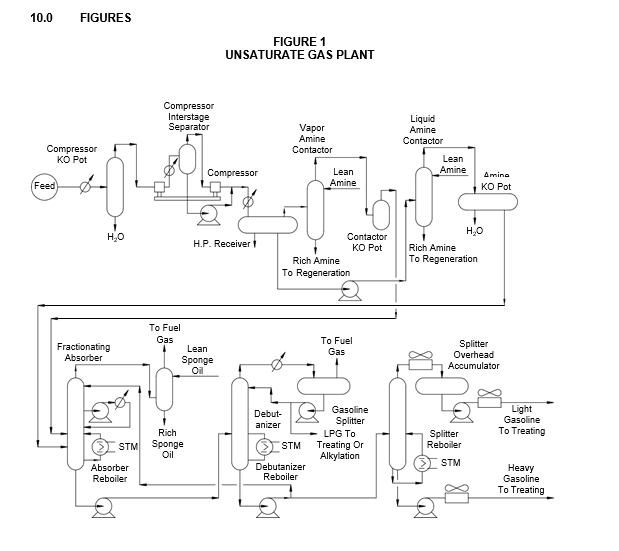
- The purpose of the Unsaturate Gas Plant is to recover light hydrocarbons from cracked gases for subsequent processing.
- A representative Unsaturate Gas Plant is shown in Figure 1. Since each refinery charges different stocks and has specific product slate requirements, this general scheme usually is modified for the various refinery installations.
- In thermofor catalytic cracking (TCC) and fluid catalytic cracking (FCC) units, wet gas streams from overhead accumulators or fractionation receivers are compressed, amine contacted to remove hydrogen sulfide and charged to the fractionating absorber. In the absorption section, hydrocarbons are assimilated by the lean oil (debutanized gasoline) flowing countercurrent with the gas. In the fractionation section, the light boiling fractions of the liquid and the saturated lean oil are separated by heat supplied through a reboiling action. The fractionating absorber off–gas is routed to a sponge absorber for recovery of low molecular weight lean oil carryover. Either a TCC syntower or an FCC main column side stream may be used as the absorption medium in the sponge absorber. The rich sponge oil is returned to the TCC syntower or FCC main column for recovery of absorbed components.
- The fractionating absorber bottoms are charged to the debutanizer, which also serves as a lean oil still. The hydrocarbon (C3/C4) overhead usually is used as alkylation unit feed. A portion of the debutanized gasoline is returned to the top of the fractionating absorber. The net debutanizer bottoms are sent to the gasoline splitter for separation into light and heavy gasoline and further treating.
- Another common variation of this process flow involves removal of hydrogen sulfide subsequent to the absorption step.
MAJOR MATERIALS AND CORROSION CONSIDERATIONS
- In gas plants handling TCC streams, corrosion problems are caused by hydrogen sulfide and under–deposit attack from ammonium compounds. Carbon steel equipment has performed satisfactorily in such plants; however, the use of filming amine inhibitors and water slugging has been necessary in some units.
- In gas plants handling FCC stream, corrosion problems are caused by hydrogen sulfide and cyanides. Carbon steel exposed to moist hydrogen sulfide and cyanides may corrode, hydrogen blister or stress crack. In this service, carbon steel generally is used with a water wash and the addition of corrosion inhibitors. Equipment in severe service usually is epoxy lined; for example, compressor receivers or compressor suction knockout drums.
- Fully killed carbon steel normally is used for equipment exposed to moist hydrogen sulfide (greater than 50 ppm H2S in the water phase).
- Copper alloy tubes generally are used in water coolers and condensers if the ammonia content in the aqueous phases does not exceed 0.1 percent by weight. Where ammonia content is higher, E–Brite 26–1, Type 430 stainless steel or carbon steel tubes are used; however, carbon steel tubes may be subject to inherent fouling problems and may require frequent replacement. When zinc–chromate treated water is available for cooling, all–carbon steel exchangers may be used. Air coolers with carbon steel tubes have performed satisfactorily.
- The channel, tubesheets and tubes in fractionating tower reboilers, which are heated with hot oil and operate above 550F, are constructed from 5Cr–1/2Mo steel; E–Brite 26–1 tubes may be used as an alternative if the temperature is less than 700F.
CONSTRUCTION MATERIALS
- Recommended construction materials are presented in Table 1 through Table 3 for vessels, exchangers, piping and other equipment such as heaters and pumps.
- The materials of construction and corrosion allowances designated in this Practice are minimum requirements selected to provide satisfactory service in units operating at standard design conditions. Appropriate material specifications for piping components and equipment are covered in the Engineering Practices shown in Table 4.
- Post weld heat treatment (PWHT) and material hardness requirements for AES service shall be in accordance with EP 10–2–1 and EP 10–2–3.
CORROSION CONTROL METHODS
Plants Handling TCC Streams, Delayed Coker Streams or Both
- Fouling and under–deposit corrosion may occur if high levels of ammonium hydrosulfide and ammonium chloride are present in the gas streams. The principal problem area is the high– pressure section of the gas compressors where water is evaporated.
- The gas stream from the low–pressure section should be water washed to remove ammonium compounds and sulfides.
- When necessary to mitigate fouling, antifoulants may be added in the high–pressure stages.
- Filming amine corrosion inhibitors may be added to the gas stream feed or to overhead systems of fractionating towers if high corrosion rates are experienced in carbon steel equipment.
Plants Handling FCC Gas Streams
- Corrosion is generally due to the presence of moist hydrogen sulfide and cyanides; fouling is usually the result of ammonium compounds.
- To remove cyanides, wash gas stream with water (about 6.5 pH).
- In areas where water condenses, corrosion rates are not expected to be more than 2 mils per year on carbon steel components. If extensive corrosion of carbon steel equipment is experienced, a film–forming corrosion inhibitor should be injected into the incoming gas stream.
- Retractable corrosometer probes shall be installed between the high–pressure coolers and the high–pressure receiver and near the middle of the absorber tower.
- Hydrogen activity shall be monitored to determine the effectiveness of controls. Hydrogen buildup in the probes should not exceed 10 psi per week, at the following locations.
- High–pressure receiver
- Top of vessel.
- Side just above liquid level.
- Main absorber
- Second manway from bottom.
- Third manway from bottom at liquid level.
- Second manway from top.
- Above top tray in stripper tower
- Debutanizer overhead receiver
- Bottom boot.
- Top of vessel.
- Daily spot tests for cyanide and thiocyanate shall be made in water drawn from the high– pressure receiver and debutanizer overhead accumulator.
MATERIALS CONSIDERATIONS DURING FABRICATION
- In FCC Unsaturate Gas Plants, the hardness of welds and heat–affected zones shall be in accordance with EP 10–2–1.
- Carbon steel equipment exposed to wet hydrogen sulfide shall be post–weld heat treated. Hardness of welds and heat–affected zones and PWHT requirements shall be in accordance with EP 10–2–1 and EP 10–2–3.
- Inhibited admiralty tubes shall be annealed.
- Streams containing 50 ppm or more of hydrogen sulfide (H2S) shall be considered H2S bearing streams.
9.0 TABLES
TABLE 1
CONSTRUCTION MATERIALS – VESSELS
| EQUIPMENT | COMPONENT | MATERIALS |
|---|---|---|
| Compressor KO Pot | Shell | CS with 0.15 inch CA (1)(2) |
| Compressor Interstage Separator and High–Pressure Receiver | Shell | CS with 0.15 inch CA (1) |
| Vapor Amine Contactor and Contactor KO Pot, Liquid Amine Contactor and Amine KO Pot | Shell | CS with 0.125 inch CA (1) |
| Vapor Amine Contactor and Contactor KO Pot, Liquid Amine Contactor and Amine KO Pot | Trays | Type 410S |
| Fractionating Absorber, Sponge Absorber, Debutanizer, Debutanizer Overhead Accumulator |
Shell | CS with 0.125 inch CA (1) |
| Fractionating Absorber, Sponge Absorber, Debutanizer, Debutanizer Overhead Accumulator |
Trays | Type 410S |
| Gasoline Splitter and Splitter Overhead Accumulator | Shell | CS with 0.125 inch CA |
| Gasoline Splitter and Splitter Overhead Accumulator | Trays | Type 410S |
Nomenclature: CS = Carbon Steel
CA = Corrosion Allowance
NOTES:
- Post weld heat treat equipment. Weld and heat–affected zone hardness and PWHT requirements shall be in accordance with EP 10–2–1 and EP 10–2–3.
- The compressor KO pot in FCC Unsaturate Gas Plants should be sandblasted and coated with three coats of high build epoxy, and the corrosion allowance should be reduced to 0.10 inch.
TABLE 2
CONSTRUCTION MATERIALS – EXCHANGERS
| EQUIPMENT | COMPONENT | MATERIALS |
|---|---|---|
| Gas Feed Cooler, Compressor Interstage Coolers and Compressor Aftercoolers – Water Coolers |
Shell and Channel (Ammonia < 1000 ppm) | CS with 0.125 inch CA (1) |
| Gas Feed Cooler, Compressor Interstage Coolers and Compressor Aftercoolers – Water Coolers |
Tubesheet (Ammonia < 1000 ppm) | NB (2)(5) |
| Gas Feed Cooler, Compressor Interstage Coolers and Compressor Aftercoolers – Water Coolers |
Baffles (Ammonia < 1000 ppm) | Muntz metal (2)(5) |
| Gas Feed Cooler, Compressor Interstage Coolers and Compressor Aftercoolers – Water Coolers |
Tubes (Ammonia < 1000 ppm) | Inhibited admiralty (2)(5) |
| Gas Feed Cooler, Compressor Interstage Coolers and Compressor Aftercoolers – Water Coolers |
Shell and Channel (Ammonia > 1000 ppm) | CS with 0.125 inch CA (1) |
| Gas Feed Cooler, Compressor Interstage Coolers and Compressor Aftercoolers – Water Coolers |
Tubesheet (Ammonia > 1000 ppm) | CS Clad with 304 or 316 or solid SS |
| Gas Feed Cooler, Compressor Interstage Coolers and Compressor Aftercoolers – Water Coolers |
Baffles (Ammonia > 1000 ppm) | 304 SS |
| Gas Feed Cooler, Compressor Interstage Coolers and Compressor Aftercoolers – Water Coolers |
Tubes (Ammonia > 1000 ppm) | E–Brite 26–1 or equivalent (3) |
| Gas Feed Cooler, Compressor Interstage Coolers and Compressor Aftercoolers – Air Coolers | Header | CS with 0.25 inch CA (1) |
| Gas Feed Cooler, Compressor Interstage Coolers and Compressor Aftercoolers – Air Coolers | Tubes | CS (seamless) |
| Fractionator Absorber Intercoolers and Debutanizer Overhead Cooler – Water Coolers | Shell and Channel | CS with 0.125 inch CA (1) |
| Fractionator Absorber Intercoolers and Debutanizer Overhead Cooler – Water Coolers | Tubesheet | NB (5) |
| Fractionator Absorber Intercoolers and Debutanizer Overhead Cooler – Water Coolers | Baffles | Muntz metal (5) |
| Fractionator Absorber Intercoolers and Debutanizer Overhead Cooler – Water Coolers | Tubes | Inhibited admiralty (5) |
| Fractionator Absorber Intercoolers and Debutanizer Overhead Cooler – Air Cooler | Header | CS with 0.125 inch CA (1) |
| Fractionator Absorber Intercoolers and Debutanizer Overhead Cooler – Air Cooler | Tubes | CS |
| Absorber, Debutanizer and Splitter Reboilers | Shell, Channel and Tubesheet | CS with 0.125 inch CA (4) |
| Absorber, Debutanizer and Splitter Reboilers | Baffles | CS |
| Absorber, Debutanizer and Splitter Reboilers | Tubes | CS (4) |
| Gasoline Splitter Overhead Cooler and Gasoline Product Cooler – Water Coolers | Shell and Channel | CS + 0.125 inch CA |
| Gasoline Splitter Overhead Cooler and Gasoline Product Cooler – Water Coolers | Tubesheet | NB |
| Gasoline Splitter Overhead Cooler and Gasoline Product Cooler – Water Coolers | Baffles | Muntz metal |
| Gasoline Splitter Overhead Cooler and Gasoline Product Cooler – Water Coolers | Tubes | Inhibited admiralty |
| Gasoline Splitter Overhead Cooler and Gasoline Product Cooler – Air Coolers | Header | CS + 0.125 inch CA |
| Gasoline Splitter Overhead Cooler and Gasoline Product Cooler – Air Coolers | Tubes | CS |
TABLE 2
CONSTRUCTION MATERIALS FOR UNSATURATE GAS PLANTS – EXCHANGERS (CONTINUED)
Nomenclature: CS = Carbon Steel
CA = Corrosion Allowance NB = Naval Brass
SS = Stainless Steel
NOTES:
- Post weld heat treat equipment. Weld and heat–affected zone hardness and PWHT requirements shall be in accordance with EP 10–2–1 and EP 10–2–3.
- Ferrous tube bundles may be required under conditions where ammonia concentrations may build up (over 1000 ppm) in stagnant areas.
- Depending on the quality of available cooling water, seamless carbon steel tubes may be substituted for E–Brite 26–1.
- If metal temperatures of channels or tubes exceed 550F, replace carbon steel with 5 Cr–1/2 Mo steel.
- (*) Consult the Owner’s Engineer for other alloy selections.
TABLE 3
CONSTRUCTION MATERIALS – PIPING COMPONENTS AND OTHER EQUIPMENT
| EQUIPMENT | COMPONENT | MATERIALS |
|---|---|---|
| All Process Lines | Pipe (Metal Temperature < 500F) | CS with 0.125 inch CA (1) |
| All Process Lines | Pipe ( > 500F) | 5Cr–1/2Mo with 0.10 inch CA (1) |
| Valves in CS Lines | Body | CS with 0.125 inch CA |
| Valves in CS Lines | Trim | 13Cr/Stellite (2) |
| Valves in 5Cr – 1/2Mo Lines | Body | 5Cr – 1/2Mo with 0.10 inch CA |
| Valves in 5Cr – 1/2Mo Lines | Trim | 13Cr/Stellite (2) |
| Sour Hydrocarbon Streams and Rich Amine Pumps | Casing | CS with 0.125 inch CA |
| Sour Hydrocarbon Streams and Rich Amine Pumps | Impeller | 12% Cr |
| All Other Pumps | Casing | CS with 0.125 inch CA |
| All Other Pumps | Impeller | CI (3) |
| Wet Gas Compressors | Casing | CS and low–alloy steel (4) |
Nomenclature: CS = Carbon Steel
CA = Corrosion Allowance CI = Cast Iron
NOTES:
- Hardness of welds and heat–affected zones exposed to moist hydrogen sulfide (>50 ppm H2S) shall be in accordance with EP 10–2–1 and EP 10–2–3.
- If cyanide content exceeds 10 ppm in wet hydrogen sulfide service, use Type 316 valve trim.
- In multi–stage pumps, use CS impellers.
- Tensile strength shall not exceed 90,000 psi; weld and heat–affected zone hardness shall be in accordance with EP 10–2–1.
TABLE 4
MATERIAL SPECIFICATIONS AND NDE REQUIREMENTS
| Piping Component or Equipment Type | Engineering Practice |
|---|---|
| Piping components and valve trim Pressure vessel & heat exchangers Pressure vessels – Internals Atmospheric storage tanks Low pressure storage tanks Pressure storage spheres |
EP 5–1–1 EP 7–1–1 EP 7–2–1 EP 9–1–1 EP 9–2–1 EP 9–4–1 |
© 2026 Inflection Point Engineering, LLC. All rights reserved. The content of this page — including calculation methods, reference data, written analysis, interactive tools, and source code — is the intellectual property of Inflection Point Engineering, LLC and is protected under applicable copyright, trademark, and trade secret laws. Unauthorized reproduction, redistribution, modification, or derivative use in whole or in part is prohibited without prior written consent.
Disclaimer. This material is provided for informational and educational purposes only and does not constitute professional engineering advice. Calculations, reference data, and methodologies are based on published standards and accepted engineering practice but are not a substitute for engineering judgment, site-specific analysis, or review by a licensed Professional Engineer. Inflection Point Engineering, LLC makes no warranties, express or implied, regarding the accuracy, completeness, or fitness for a particular purpose of any content presented here, and shall not be liable for any direct, indirect, incidental, or consequential damages arising from its use. Users assume all risk associated with applying this content to real-world design, operations, or decisions.
© 2026 Inflection Point Engineering, LLC. All rights reserved.