 Section 10 — Material Requirements
Catalytic Hydrodesulphurizer
IPE Engineering Practice IPE-EP-10-1-4
Document number: IPE-EP-10-1-4 · Section: 10 — Material Requirements
SCOPE
- This Practice presents recommendations for the selection and use of materials for catalytic hydrodesulfurization (CHD) units.
- This Practice is for guidance purposes and deviation per EP 1–1–3 is not required.
- An asterisk (*) indicates that a decision by the Owner or Owner’s Engineer is required, or that additional information is to be furnished by the Purchaser.
2.0 REFERENCE
The latest edition of the following standards and publications are referred to herein.
STANDARDS AND PUBLICATIONS
| Engineering Practices | Engineering Practices |
|---|---|
| EP 1–1–3 | Deviations to Engineering Practices |
| EP 5–1–1 | General Piping Design |
| EP 7–1–1 | Pressure Vessels |
| EP 7–2–1 | Pressure Vessel Internals |
| EP 8–1–1 | TEMA Shell and Tube Heat Exchangers |
| EP 9–1–1 | Atmospheric Storage Tanks |
| EP 9–2–1 | Low Pressure Storage Tanks |
| EP 9–4–1 | Pressure Storage Spheres |
| EP 10–2–1 | Material Requirements for Aggressive Environmental Services |
| EP 10–2–3 | Material Hardness Requirements |
DEFINITIONS
- Aggressive Environmental Service (AES) – Process services which result in material degradation such as cracking, scaling, blistering, and severe pitting and/or corrosion. Examples of such services are hydrogen service, wet hydrogen sulfide, cyanides, caustic, amine, and hydrofluoric acid. AES process fluids are defined in EP 10–2–1.
- Equipment – Each pump, compressor, product accumulator vessel, pressure relief device, valve, sampling connection system, open–ended valve or line, flange or other connector in VOC service, or devices or systems required by this Practice.
- Owner – Refining Company.
- Owner’s Engineer – A Refining Company appointed engineer.
GENERAL
- This Practice is to be used for the Owner’s projects when specifying construction materials for Catalytic Hydrodesulfurizer (CHD) units.
- The purpose of the CHD units is to remove sulfur from distillate stocks by hydrogen contact over a suitable catalyst. The feed may be kerosene, fuel oil, diesel, gas oil or a wider cut containing lighter or heavier fractions, or both.
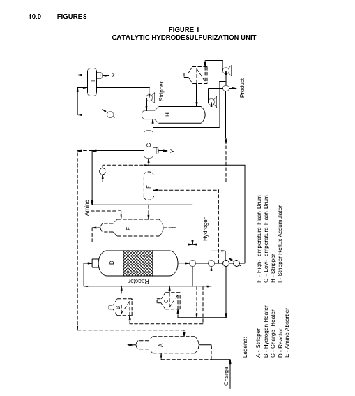
- In a typical CHD unit, see Figure 1, the charge is deaerated, heated, mixed with hydrogen and passed over a pelletized catalyst in a reactor under pressure. In some designs, the hydrogen stream is preheated prior to mixing with the charge. The reactor effluent is cooled and the liquid product separated from the unreacted hydrogen and hydrogen sulfide in the high– and low– temperature flash drums. Normally, the hydrogen–rich gas is recycled after amine scrubbing while the liquid product flows to the stripper. In the stripping column, the liquid is stripped of dissolved hydrogen sulfide and light hydrocarbons. Stripper bottoms are the desulfurized product; the overhead gas is used for fuel. In Figure 1, the components drawn in solid lines are essential to the process. Components drawn in dashed lines are optional items that may be included in the design.
MAJOR MATERIALS AND CORROSION CONSIDERATIONS
- In CHD units, equipment exposed to high–pressure hydrogen at high temperatures is protected from hydrogen attack by proper use of chromium–molybdenum steels and austenitic stainless steels.
- Hydrogen sulfide and mixtures of hydrogen and hydrogen sulfide are corrosive to carbon steel above 550°F and 500°F, respectively. Excessive corrosion and scale formation are controlled by use of chromium–molybdenum steels (H2S only) and austenitic stainless steels (H2 and H2S mixtures).
- Copper alloy tubes generally are used in water coolers and condensers. When zinc–chromate treated water is available for cooling, all–carbon–steel exchangers may be used. Air coolers utilizing carbon steel tubes provide satisfactory service, but have experienced corrosion due to ammonium chloride or ammonium hydrosulfide deposits.
- The hydrogen chloride, formed from hydrogenation of chlorine compounds, may condense as acid or as an ammonium chloride salt. The condensation of hydrogen chloride and water may occur in the lower temperature parts of the effluent system during operation, or farther upstream on shutdown. Chloride stress corrosion cracking or pitting of austenitic stainless steels and pitting or general attack on carbon steel or low–alloy steel may result. Where such conditions are anticipated and other corrosion control measures may not be completely relied upon to prevent attack, Inconel, Hastelloy C or Monel may be used for valve trim and other critical items. Monel shall not be used in sulfiding environments where temperatures exceed 450°F.
- Ammonium hydrosulfide (NH4HS) can form in high–temperature, high pressure units in which ammonia and hydrogen sulfide are present. The presence of moist NH4HS in effluent streams is especially corrosive to carbon steel tubing at velocities greater than 20 feet per second. Heat exchanger tubing fabricated from Type 321, Type 2205 and Incoloy 800 materials has been successfully used under such conditions. Selection of tubing material will depend on cooling water quality, presence of chlorides and extent of NH4HS formation.
9.0 TABLES
TABLE 1
CONSTRUCTION MATERIALS – VESSELS
| EQUIPMENT | COMPONENT | MATERIALS |
|---|---|---|
| Stripper | Shell | CS with 0.125 inch CA |
| Reactor | Shell | 2–1/4 Cr–1 Mo clad with 0.125 inch minimum Type 321 or weld overlaid with 0.187 inch minimum Type 347 |
| Reactor | Internals | Type 321 or Type 347 |
| High–Temperature Flash Drum (Separator) | Shell (Metal Temperature < 500F) |
CS with 0.15 inch CA (2) |
| High–Temperature Flash Drum (Separator) | Shell ( > 500F) | Cr–Mo steel clad with 0.125 inch minimum Type 321 or weld overlaid with 0.187 inch minimum Type 347(1) |
| Low–Temperature Flash Drum (Separator) | Shell | CS with 0.125 inch CA (2) |
| Low–Temperature Flash Drum (Separator) | Demisters | Monel (3) |
| Amine Absorber | Shell | CS with 0.125 inch CA (2) |
| Amine Absorber | Trays | Type 410S |
| Amine Absorber | Demister | Type 316 |
| Stripper | Shell | CS with 0.20 inch CA (2) |
| Stripper | Trays, Tray supports, Downcomers | Type 410S |
| Stripper Reflux Accumulator | Shell | CS with 0.15 inch CA (2) |
| Stripper Reflux Accumulator | Demister | Type 316 |
Nomenclature: CS = Carbon Steel
CA = Corrosion Allowance
NOTES:
- For temperatures between 500F and 550F, consideration should be given to using CS clad with Type 410S. Suitability of cladding will depend on the corrosivity of the CHD reactor effluent stream, temperature and hydrogen partial pressure.
- Vessel to be PWHT. Hardness of welds and heat–affected zones and PWHT requirements shall be in accordance with EP 10– 2–1 and EP 10–2–3.
- Demisters consisting of Monel grids and Teflon screens may also be used.
TABLE 2
CONSTRUCTION MATERIALS–EXCHANGERS
| EQUIPMENT | COMPONENT | MATERIALS |
|---|---|---|
| Feed/Reactor Effluent Exchanger – Feed Side (without H2) | Shell (Metal Temperature < 500 F) |
CS with 0.125 inch CA (1) |
| Feed/Reactor Effluent Exchanger – Feed Side (without H2) | Baffles (< 500 F) | CS |
| Feed/Reactor Effluent Exchanger – Feed Side (without H2) | Shell (> 500 F) | CS clad with 0.125 inch minimum 316L or solid 5 Cr–1/2 Mo with 0.125 inch CA |
| Feed/Reactor Effluent Exchanger – Feed Side (without H2) | Baffles ( > 500 F) | Type 410 |
| Feed/Reactor Effluent Exchanger – Reactor Effluent Side | Channel and Tubesheets | Cr–Mo clad with 0.125 inch minimum Type 321 or weld overlaid with 0.187 inch minimum Type 347 |
| Feed/Reactor Effluent Exchanger – Reactor Effluent Side | Tubes | Type 304L, 321(2) |
| Gas Charged Feed/Reactor Effluent Exchanger – Feed Side (with H2) | Shell (Metal Temperature < 500F) |
CS with 0.125 inch CA (1) |
| Gas Charged Feed/Reactor Effluent Exchanger – Feed Side (with H2) | Baffles (< 500F) | CS |
| Gas Charged Feed/Reactor Effluent Exchanger – Feed Side (with H2) | Shell ( > 500F and less than 50 ppm H2S) | Cr–Mo steel with 0.125 inch CA (1) |
| Gas Charged Feed/Reactor Effluent Exchanger – Feed Side (with H2) | Baffles ( > 500F and less than 50 ppm H2S) | Cr–Mo steel |
| Gas Charged Feed/Reactor Effluent Exchanger – Feed Side (with H2) | Shell ( > 500F and more than 50 ppm H2S) | Cr–Mo steel clad with 0.125 inch minimum Type 321 or weld overlaid with 0.187 inch minimum Type 347 |
| Gas Charged Feed/Reactor Effluent Exchanger – Feed Side (with H2) | Baffles ( > 500F and more than 50 ppm H2S) | Type 304 |
| Gas Charged Feed/Reactor Effluent Exchanger Reactor – Effluent Side | Channel, Tube Sheets | Cr–Mo steel clad with 0.125 inch minimum Type 321 or weld overlaid with 0.187 inch minimum Type 347 |
| Gas Charged Feed/Reactor Effluent Exchanger Reactor – Effluent Side | Tubes | Type 304L, 321(2) |
| Stripper Feed/Bottoms Exchanger | Shell (Metal Temperature < 500F) |
CS with 0.125 inch CA (1) |
| Stripper Feed/Bottoms Exchanger | Baffles (< 500F) | CS |
| Stripper Feed/Bottoms Exchanger | Shell ( > 500F) | CS with 0.20 inch CA (1) |
| Stripper Feed/Bottoms Exchanger | Baffles ( > 500F) | CS |
| Stripper Feed/Bottoms Exchanger | Channel | CS with 0.25 inch CA |
| Stripper Feed/Bottoms Exchanger | Tubesheets | Type 410SS |
| Stripper Feed/Bottoms Exchanger | Tubes | Type 430 |
TABLE 2 (CONTINUED) CONSTRUCTION MATERIALS – EXCHANGERS
| EQUIPMENT | COMPONENT | MATERIALS |
|---|---|---|
| Stripper Bottoms/Exchanger | Shell, Channel | CS with 0.125 inch CA |
| Stripper Bottoms/Exchanger | Tube Sheets, Baffles | CS |
| Stripper Bottoms/Exchanger | Tubes | CS |
| Reactor Effluent Air Cooled Exchanger | Header | CS with 0.15 inch CA (1) |
| Reactor Effluent Air Cooled Exchanger | Tubes | CS (seamless) |
| Stripper Overhead Air– Cooled Condenser | Header | CS with 0.125 inch CA (1)(3) |
| Stripper Overhead Air– Cooled Condenser | Tubes | CS (seamless) |
| Air–Cooled Product Coolers | Header | CS with 0.125 inch CA |
| Air–Cooled Product Coolers | Tubes | CS |
| Water–Cooled Product Coolers | Shell | CS with 0.125 inch CA |
| Water–Cooled Product Coolers | Tube Sheets | NB, or carbon steel NB clad |
| Water–Cooled Product Coolers | Tube Supports | Muntz Metal or NB (wet stream) or CS (dry stream) |
| Water–Cooled Product Coolers | Tubes | Inhibited Admiralty |
Nomenclature: CS = Carbon Steel
CA = Corrosion Allowance NB = Naval Brass (SB171)
NOTES:
- Welds and heat–affected zones and PWHT requirements shall be in accordance with EP 10–2–1 and EP 10–2–3. All exchanger shells or headers subject to moist H2S (greater than 50 ppm H2S) shall be post weld heat treated.
- (*) If stainless steel U–tubes are used, they shall be heat treated after bending, in accordance with EP 8–1–1. Other alloys such as AL6XN may be recommended; consult the Owner’s Engineer.
(4) (*) Aggressive environments, EP 10–2–1, should be reviewed to specify other materials; consult the Owner’s Engineer.
TABLE 3
CONSTRUCTION MATERIALS–OTHER EQUIPMENT
| EQUIPMENT | COMPONENT | MATERIALS |
|---|---|---|
| Reactor Feed Lines (without hydrogen) (1)(3) | Pipe (Metal Temperature < 500F) | CS with 0.125 inch CA |
| Reactor Feed Lines (without hydrogen) (1)(3) | Pipe ( > 500F and < 700F) | 5Cr–1/2 Mo with 0.10 inch CA |
| Reactor Feed Lines (without hydrogen) (1)(3) | Pipe ( > 700F) | 9Cr–1 Mo with 0.10 inch CA or 321 SS with 0.10 inch CA |
| Hydrogen Gas Charge or Oil Charge Mixed with Hydrogen (1)(3) | Pipe (Metal Temperature < 500F) | CS with 0.125 inch CA |
| Hydrogen Gas Charge or Oil Charge Mixed with Hydrogen (1)(3) | Pipe ( > 500F) | Type 321 with 0.05 inch CA (2) |
| Reactor Effluent and High– Temperature Separator Overhead Vapor Line (1)(3) | Pipe (Metal Temperature < 500F) | CS with 0.125 inch CA |
| Reactor Effluent and High– Temperature Separator Overhead Vapor Line (1)(3) | Pipe ( > 500F) | Type 321 with 0.05 inch CA |
| Makeup Gas Lines (1)(3) | Pipe (Metal Temperature < 500F) | CS with 0.125 inch CA |
| Makeup Gas Lines (1)(3) | Pipe ( > 500F) | Type 321 with 0.05 inch CA (2) |
| High–Temperature Separator Bottoms Line (1)(3) | Pipe (Metal Temperature < 500F) | CS with 0.125 inch CA |
| High–Temperature Separator Bottoms Line (1)(3) | Pipe ( > 500F) | Type 321 with 0.05 inch CA |
| Low–Temperature Separator Bottoms and Overhead Lines, Stripper Overhead Line (1)(3) |
Pipe ( > 500F) | CS with 0.125 inch CA (1) |
| Stripper Bottoms and Stripper Reboiler Circuit (1)(3) | Pipe | CS with 0.125 inch CA (2) |
| All Other Process and Product Lines (1)(3) | Pipe | CS with 0.125 inch CA |
| Valves in CS Lines with 0.10 inch CA | Body | CS with 0.125 inch CA |
| Valves in CS Lines with 0.10 inch CA | Trim | 12Cr / Stellite |
| Valves in CS Lines with 0.20 inch CA | Body | CS with 0.20 inch CA or 5Cr–1/2 Mo with 0.125 inch CA |
| Valves in CS Lines with 0.20 inch CA | Trim | 12Cr 1 Stellite |
| Valves in 5Cr–1/2 Mo Lines | Body | 5Cr–1/2 Mo with 0.125 inch CA |
| Valves in 5Cr–1/2 Mo Lines | Trim | 12Cr / Stellite |
| Valves in 9Cr–1 Mo Lines | Body | 9Cr–1 Mo with 0.125 inch CA or 12Cr with 0.10 inch CA |
| Valves in 9Cr–1 Mo Lines | Trim | 12Cr / Stellite |
TABLE 3 (CONTINUED) CONSTRUCTION MATERIALS – OTHER EQUIPMENT
| EQUIPMENT | COMPONENT | MATERIALS |
|---|---|---|
| Feed Heater (with H2) | Tubes | 321 SS with 0.05 inch CA |
| Stripper Reboiler | Tubes | 5 Cr–1/2 Mo with 0.125 inch CA |
| Feed and Stripper Reflux Pumps | Casing | CS with 0.125 inch CA |
| Feed and Stripper Reflux Pumps | Impeller | 12% Cr |
| Stripper Bottoms and Reboiler Pumps | Casing | CS with 0.20 inch CA (2) |
| Stripper Bottoms and Reboiler Pumps | Impeller | 12% Cr |
| Makeup Recycle and Stripper Off–Gas Compressor | Casing | CS or low–alloy steel. Tensile strength should not exceed 90,000 psi; weld and heat affected zone hardness shall be in accordance with EP 10–2–1 and EP 10–2–3 (2) |
Nomenclature: CS = Carbon Steel
CA = Corrosion Allowance SS = Stainless Steel
NOTES:
- Hardness of welds and heat–affected zones exposed to moist hydrogen sulfide (greater than 50 ppm H2S) shall be in accordance with EP 10–2–1 and EP 10–2–3.
- (*) Exact materials and corrosion allowances will be dependent on stream composition, temperature and in some cases on the type of construction. For details, consult the Owner’s Engineer.
- Piping up to 16 inches shall be seamless. Welded piping must be fusion welded.
TABLE 4
MATERIAL SPECIFICATIONS AND NDE REQUIREMENTS
| Piping Components or Equipment Type | Engineering Practice |
|---|---|
| Piping Components and Valve Trim Pressure Vessel & Heat Exchangers Pressure Vessel – Internals Atmospheric Storage Tanks Low Pressure Storage Tanks Pressure Storage Spheres |
EP 5–1–1 EP 7–1–1 EP 7–2–1 EP 9–1–1 EP 9–2–1 EP 9–4–1 |
© 2026 Inflection Point Engineering, LLC. All rights reserved. The content of this page — including calculation methods, reference data, written analysis, interactive tools, and source code — is the intellectual property of Inflection Point Engineering, LLC and is protected under applicable copyright, trademark, and trade secret laws. Unauthorized reproduction, redistribution, modification, or derivative use in whole or in part is prohibited without prior written consent.
Disclaimer. This material is provided for informational and educational purposes only and does not constitute professional engineering advice. Calculations, reference data, and methodologies are based on published standards and accepted engineering practice but are not a substitute for engineering judgment, site-specific analysis, or review by a licensed Professional Engineer. Inflection Point Engineering, LLC makes no warranties, express or implied, regarding the accuracy, completeness, or fitness for a particular purpose of any content presented here, and shall not be liable for any direct, indirect, incidental, or consequential damages arising from its use. Users assume all risk associated with applying this content to real-world design, operations, or decisions.
© 2026 Inflection Point Engineering, LLC. All rights reserved.