 Section 10 — Material Requirements
Sour Water Strippers
IPE Engineering Practice IPE-EP-10-1-18
Document number: IPE-EP-10-1-18 · Section: 10 — Material Requirements
SCOPE
- This Practice provides information for the selection and use of materials in Sour Water Strippers and operational guidance for effective corrosion control.
- This Practice is for guidance purposes and deviation per EP 1–1–3 is not required.
- An asterisk (*) indicates that a decision by the Owner or Owner’s Engineer is required, or that additional information is to be furnished by the Purchaser.
2.0 REFERENCES
The latest edition of the following standards and publications are referred to herein.
STANDARDS AND PUBLICATIONS
| Engineering Practices | Engineering Practices |
|---|---|
| EP 1–1–3 | Deviations to Engineering Practices |
| EP 5–1–1 | General Piping Design |
| EP 7–1–1 | Pressure Vessels |
| EP 7–2–1 | Pressure Vessel Internals |
| EP 9–1–1 | Atmospheric Storage Tanks |
| EP 9–2–1 | Low Pressure Storage Tanks |
| EP 9–4–1 | Pressure Storage Spheres |
| EP 10–2–1 | Material Requirements for Aggressive Environmental Services |
| EP 10–2–3 | Material Hardness Requirements |
DEFINITIONS
- Aggressive Environmental Service (AES) – Process services which result in material degradation such as cracking, scaling, blistering, and severe pitting and/or corrosion. Examples of such services are hydrogen service, wet hydrogen sulfide, cyanides, caustic, amine, and hydrofluoric acid. AES process fluid are defined in EP 10–2–1.
- Equipment – Each pump, compressor, product accumulator vessel, pressure relief device, valve, sampling connection system, open–ended valve or line, flange or other connector in VOC service, or devices or systems required by this Practice.
- Owner – Refining Company.
- Owner’s Engineer – A Refining Company appointed engineer.
GENERAL
- This Practice is to be used for the Owner’s projects when specifying construction materials for sour water strippers.
- The purpose of the sour water stripper is to remove pollutants such as hydrogen sulfide, ammonia, carbon monoxide, carbon dioxide, and hydrogen cyanide from effluent water streams.
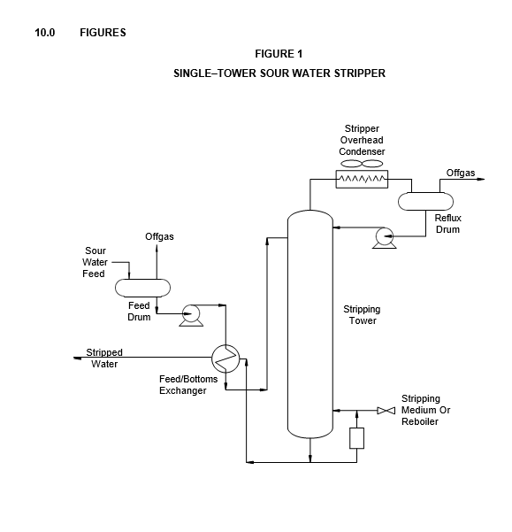
- In this Practice, only the non–acidic condensing type of stripper is covered in detail, since relatively few non–acidic non–condensing units are currently used by the Owner. In the non– condensing type of unit, the stripper overhead gas is not condensed but sent directly to incinerators or furnaces for disposal. Carbon steel is a satisfactory construction material for much of the stripper unit. In general, significant corrosion has occurred only in the top of the H2S stripper and overhead lines where gas has been allowed to condense. Maintaining temperatures above 180F prevents condensation, thereby minimizing corrosion.
- A typical non–acidic condensing sour water stripper employing a single stripping tower is shown in Figure 1. Sour water from a feed surge tank is fed through a stripper feed/bottoms exchanger into the tower where the contaminants are stripped by heat produced in a bottom reboiler, or by steam, or both. The stripped water is then removed from the bottom of the tower. The overhead stream, containing the contaminants and water vapor, is condensed and fed into the reflux drum. Liquid/gas separation occurs in the drum. The sour liquid is recycled to the stripping tower while the offgas, containing mainly hydrogen sulfide (H2S) and ammonia (NH3), is removed by incineration or is fed into a sulfur plant.Figure 1.
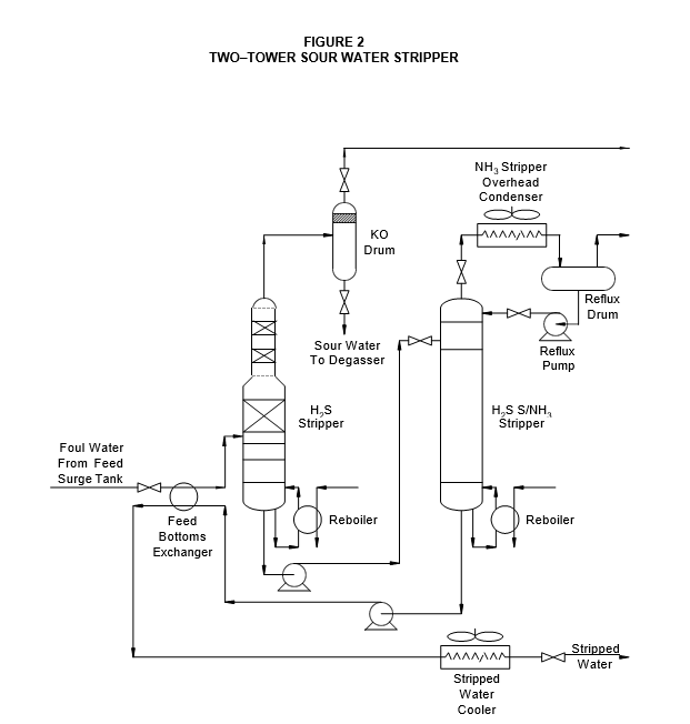
- In a two–tower design, see Figure 2, the sour water is charged into the first (H2S) tower where approximately 80 percent of the hydrogen sulfide is removed by a reboiler stripping operation. The overhead stream is generally a high–purity H2S suitable for feed to a sulfur plant. The aqueous bottoms stream is fed into the second tower (H2S/NH3) where virtually all ammonia and any remaining hydrogen sulfide are stripped from the water. The second tower section of a two–tower stripper is similar in design and operation to the single tower unit.
- Selection of the two–tower or one–tower stripper system will depend on the economics and environmental considerations of separating and recovering NH3.
MAJOR MATERIALS AND CORROSION CONSIDERATIONS
- The primary corrosion areas in sour water strippers are the overhead and reflux systems. A highly corrosive environment develops in these areas where the overhead vapor containing H2S, NH3, and hydrogen cyanide (HCN) condenses. Steam tracing and insulation of piping have been successfully used to prevent condensation in the vapor phase and permits the use of carbon steel material with minimal corrosion. When steam tracing and insulating are not practicable, materials such as Type 304 stainless steel, aluminum, titanium, and Hastelloy C have been used to control corrosion.
- In the upper portion of the H2S stripper tower and the overhead piping, condensate may combine with H2S vapor to form an acidic solution that is corrosive to carbon steel. This type of corrosion is controlled by cladding with Type 304L stainless steel in the upper portion of the tower and by heat tracing the overhead lines to prevent condensation of water vapor.
- Reflux and feed surge drums are susceptible to hydrogen blistering. The use of carbon steel with an epoxy lining has alleviated this problem.
- Many contaminants that cause stress corrosion cracking in carbon steel are contained in sour water. To prevent weld cracking, the hardness of all carbon steel welds in equipment and piping associated with sour water shall be in accordance with EP 10–2–1 and EP 10–2–3.
CONSTRUCTION MATERIALS
- Recommended construction materials are presented in Table 1 through Table 3 for vessels, exchangers, piping and other such equipment as heaters and pumps.
- The materials of construction and corrosion allowances designated in this Practice are minimum requirements selected to provide satisfactory service in units operating at standard design conditions. Appropriate material specifications for piping components and equipment are covered in the Engineering Practices shown in Table 4.
- Post weld heat treatment (PWHT) and material hardness requirements for AES service shall be in accordance with EP 10–2–1 and EP 10–2–3.
CORROSION CONTROL METHODS
- Gases in the H2S and H2S/NH3 stripper overhead condenser may form solid ammonia hydrosulfide (NH4HS) and cause plugging and corrosion. Provisions should be made for intermittent water injection to remove solid NH4HS. Water shall be injected only if warranted by pressure drop.
- Sour water feed velocity in the feed/effluent heat exchangers and reflux circuit piping shall be maintained between 3 and 6 ft/s to minimize erosion/corrosion.
- Stream velocities are limited to 40 ft/s where aluminum tubes are used in the H2S/NH3 stripper overhead condenser. Care should be taken to prevent liquid droplets from impinging on aluminum tubes either from entrainment or condensation.
- Maintain stream velocity below 50 ft/s in the H2S/NH3 stripper overhead piping.
- Monel, copper, or copper–bearing alloys shall not be used in the sour water stripper. Ammonia present in the sour water can lead to rapid corrosion and possible stress corrosion cracking of the copper containing alloys.
- (*) Avoid overfiring of reboilers; consult the Owner’s Engineer, for limitations on specific designs.
- A minimum temperature of 180ºF must be maintained in the H2S/NH3 stripper. Below this temperature, H2S is not carried overhead and acid gas concentrates in the top section of the tower. This acid gas attacks almost all materials of construction.
- Provisions for both corrosion and hydrogen activity probes should be made in the following areas:
- In the liquid and vapor space above the top tray of the H2S/NH3 stripper tower.
- In the liquid and vapor space of the reflux drum.
- Corrosion probes should be installed at the inlet and outlet of the H2S/NH3 overhead condenser and in the H2S offgas stream.
- (*) Filming amine inhibitors may be used to minimize corrosion in the stripper overhead system. For additional information, consult the Owner’s Engineer.
MATERIALS CONSIDERATIONS DURING FABRICATION
- Hardness of carbon steel weldments exposed to moist H2S shall be in accordance with EP 10– 2–1 and EP 10–2–3. Carbon steel equipment shall be postweld heat treated (see section 6.3 of this Practice).
- All austenitic stainless steel and Hastelloy C equipment shall be solution annealed.
- If titanium tubes are used in the H2S/NH3 stripper overhead condenser, special care should be exercised in properly designing and bracing them to prevent fatigue failure. Finned titanium tubes should use extruded aluminum fins to improve tube rigidity.
- Type 321, Type 347, or Type 316L stainless steels may be substituted for Type 304L, if economically favorable.
9.0 TABLES
TABLE 1
CONSTRUCTION MATERIALS—VESSELS
| EQUIPMENT | COMPONENT | MATERIALS | MATERIALS |
|---|---|---|---|
| EQUIPMENT | COMPONENT | Mild Service (1) | Severe Service |
| Feed Surge Tank | Shell | CS with 0.125 inch CA (2) or CS with 0.125 inch CA and lined with a suitable coating | CS with 0.125 inch CA (2) lined with a suitable coating |
| H2S Stripper Tower (if used) from Point 2 feet below Feed Inlet Tray to Top of Tower | Shell | CS with 0.25 inch CA (2) | CS clad with 0.125 inch minimum Type 304L (2)(7) |
| H2S Stripper Tower (if used) from Point 2 feet below Feed Inlet Tray to Top of Tower | Trays | Type 410S | Type 304L with 0.0625 inch CA |
| H2S Stripper Tower (if used) from Point 2 feet below Feed Inlet Tray to Top of Tower | Packing | Type 410S | Type 304 (3) |
| H2S Stripper Tower (if used) Remaining Portion of Tower | Shell | CS with 0.15 inch CA (2) | CS with 0.375 inch CA (2) |
| H2S Stripper Tower (if used) Remaining Portion of Tower | Trays | CS with 0.15 inch CA or Type 410S with 0.03 inch CA | Type 304L with 0.0625 inch CA (4) |
| H2S Stripper Tower (if used) Remaining Portion of Tower | Packing | Type 410S | Type 304 |
| H2S/NH3 Stripper Tower from Point 2 feet below Feed Inlet Tray to Top of Tower | Shell | CS with 0.25 inch CA (2) | CS with 0.375 inch (8)CA (2) |
| H2S/NH3 Stripper Tower from Point 2 feet below Feed Inlet Tray to Top of Tower | Trays | Type 410S with 0.03 inch CA | 304L with 0.0625 inch CA (3)(4) or 410SS with 0.0625 inch CA |
| H2S/NH3 Stripper Tower Remaining Portion of Tower | Shell | CS with 0.15 inch CA | CS with 0.375 inch CA (2) |
| H2S/NH3 Stripper Tower Remaining Portion of Tower | Trays | CS with 0.15 inch CA | CS with 0.125 inch CA or 410SS with 0.0625 inch CA |
| H2S Stripper Overhead Knockout Drum | Shell | CS with 0.25 inch CA (2) (3) | CS with 0.25 inch CA (2) (3) or Aluminum |
| H2S/NH3 Stripper Reflux Drum or Overhead Accumulator | Shell | CS with 0.25 inch CA (2)(5) lined with Valspar Hi–Build Epoxy 78–W–3 or 78–D–7 (6) | CS with 0.25 inch CA (2) (5) lined with Valspar Hi–Build Epoxy 78–W–3 or 78–D–7 (6) or Aluminum (solid) |
TABLE 1
CONSTRUCTION MATERIALS—VESSELS (Continued)
Nomenclature: CS = Carbon Steel
CA = Corrosion Allowance
NOTES:
- A sour water stripper unit shall be considered in mild service provided none of the following levels is exceeded in the sour water: H2S–4000 ppm, NH3–1500 ppm, CN 10 ppm.
- (*) Vessel shall be postweld heat treated (PWHT). Hardness of welds and heat–affected zones shall be in accordance with EP 10–2–1 and EP 10–2–3. A greater corrosion allowance may be used instead of cladding; consult the Owner’s Engineer.
- If demisters are used, they shall have a Teflon screen and Type 304L grid.
- If no welding is performed, Type 304 may be used in place of Type 304L.
- Nozzles and deflection plates shall be located so that no liquid stream impinges on drum walls.
- Use of epoxy coatings shall be limited to temperatures below 200F; Plasite 9500 may be used to resist steam–out during shutdowns.
- (*) A higher corrosion allowance may be used instead of cladding, consult the Owner’s Engineer.
- (*) For severe services higher alloys may be required. Consult the Owner’s Engineer.
TABLE 2
CONSTRUCTION MATERIALS—EXCHANGERS
| Equipment | Component | Materials | Materials |
|---|---|---|---|
| Equipment | Component | Mild Service (1) | Severe Service |
| H2S/NH3 Stripper Feed/Bottoms Exchanger (2) | Shell | CS with 0.125 inch CA (8) | CS with 0.25 inch CA (8) |
| H2S/NH3 Stripper Feed/Bottoms Exchanger (2) | Channel | CS with 0.125 inch CA | CS with 0.25 inch CA |
| H2S/NH3 Stripper Feed/Bottoms Exchanger (2) | Tubesheet | CS with 0.125 inch CA | CS with 0.25 inch CA |
| H2S/NH3 Stripper Feed/Bottoms Exchanger (2) | Tubes | CS, seamless (3) | CS, seamless (3) |
| H2S Stripper Reboiler and H2S/NH3 Stripper Reboiler | Shell | CS with 0.125 inch CA (8) | CS with 0.25 inch CA (8) |
| H2S Stripper Reboiler and H2S/NH3 Stripper Reboiler | Vestibule | CS with 0.125 inch CA | CS with 0.25 inch CA |
| H2S Stripper Reboiler and H2S/NH3 Stripper Reboiler | Tubesheets | CS with 0.125 inch CA | CS with 0.125 inch CA |
| H2S Stripper Reboiler and H2S/NH3 Stripper Reboiler | Tubes | CS, seamless (3) | CS, seamless (3) |
| H2S/NH3 Stripper Overhead Condenser | Header | Al with 0.125 inch CA | Titanium Clad Carbon Steel (5)(6) |
| H2S/NH3 Stripper Overhead Condenser | Tubes | Al 3003 or 3004 (4) | Titanium (5)(7), Inconel 600 or Hastelloy C 276/22 |
| Stripped Water Air Coolers | Header | CS with 0.125 inch CA | CS with 0.125 inch CA |
| Stripped Water Air Coolers | Tubes | CS | CS |
| Stripped Water/Water Coolers (9) | Shell | CS with 0.125 inch CA | CS with 0.125 inch CA |
| Stripped Water/Water Coolers (9) | Tubesheet | NB | NB |
| Stripped Water/Water Coolers (9) | Baffles | Muntz Metal | Muntz Metal |
| Stripped Water/Water Coolers (9) | Tubes | Inhibited Admiralty | Inhibited Admiralty |
Nomenclature: CS = Carbon Steel
CA = Corrosion Allowance Al = Aluminum
NB = Naval Brass (SB171, C46500 preferred)
NOTES:
- A sour water stripper unit shall be considered in mild service provided none of the following levels is exceeded in the sour water: H2S– 4000 ppm, NH3 – 1500 ppm, CN–10 ppm.
- Maintain sour water feed velocity between 3 and 6 ft/s.
- (*) Welded tubes may be substituted, subject to the Owner’s approval. Furthermore, the welded tubes shall be annealed or normalized, after welding and supplied by an approved vendor.
- Limit stream velocity in aluminum tubes to 40 ft/s maximum.
- (*) Under some process conditions, an all–aluminum air cooler may be a more cost effective choice. Consult the Owner’s Engineer.
- Both titanium and Hastelloy C 276/22 are highly resistant to the H2O/H2S/NH3 environment. Titanium must not be rolled into a bare carbon steel header.
- Aluminum finned titanium tubes are acceptable.
- Vessel shall be post weld heat treated (PWHT). Hardness of welds and heat affected zones shall be in accordance with EP 10–2–1 and EP 10–2–3.
- (*) Other materials may be considered; consult the Owner’s Engineer.
TABLE 3
CONSTRUCTION MATERIALS—PIPING COMPONENTS AND OTHER EQUIPMENT
| EQUIPMENT | COMPONENT | MATERIALS | MATERIALS |
|---|---|---|---|
| EQUIPMENT | COMPONENT | Mild Service (1) | Severe Service |
| H2S Stripper Overhead Line (tower to condenser) | Pipe | CS with 0.125 inch CA (2)(3) | CS with 0.125 inch CA (2)(3) |
| H2S Vapor Line (from reflux drum to disposal) | Pipe | CS with 0.125 inch CA (2)(3) | CS with 0.125 inch CA (2)(3) |
| H2S/NH3 Stripper Run Down Line (condenser to reflux drum) | Pipe | CS with 0.15 inch CA (3) | Aluminum with 0.125 inch CA or Type 316L with 0.05 inch CA |
| H2S/NH3 Reflux Line (reflux drum to tower) | Pipe | CS with 0.15 inch CA (3) | Aluminum with 0.125 inch CA or Type 316L with 0.05 inch CA |
| All Other Lines | Pipe | CS with 0.125 inch CA (3) | CS with 0.125 inch CA (3) |
| Valves in H2S Stripper Overhead, H2S/NH3 Stripper Overhead and Reflux Services | Body | Hastelloy C276 (4) | Hastelloy C276 (4) |
| Valves in H2S Stripper Overhead, H2S/NH3 Stripper Overhead and Reflux Services | Trim | Hastelloy C276 (4) or CS Teflon–lined ball and plug valves | Hastelloy C276 (4) or CS Teflon–lined ball and plug valves |
| Valves in H2S Stripper Overhead, H2S/NH3 Stripper Overhead and Reflux Services | Orifice Plates | Hastelloy C276, or Titanium Gr 2 (4) | Hastelloy C276, or Titanium Gr 2 (4) |
| Valves in All Other Services | Body | CS with 0.125 inch CA | CS with 0.125 inch CA |
| Valves in All Other Services | Trim | 12% Cr | Type 316 or Stellite |
| H2S/NH3 Stripper Reflux Pump | Casing | Hastelloy C276 (4), Titanium (5) or Teflon– lined CS | Hastelloy C276 (4), Titanium (5) orTeflon–lined CS |
| H2S/NH3 Stripper Reflux Pump | Impeller | Hastelloy C276 (4), Titanium (5) or Teflon– lined CS | Hastelloy C276 (4), Titanium (5) or Teflon–lined CS |
| H2S Bottoms, H2S/NH3 Bottoms, and Sour Water Sump Pumps | Casing | CS with 0.125 inch CA | CS with 0.125 inch CA |
| H2S Bottoms, H2S/NH3 Bottoms, and Sour Water Sump Pumps | Impeller | Type 316 or Ni–Resist | Type 316 or Ni Resist |
| Stripper Condensate Pump | Casing | CS with 0.125 inch CA | CS with 0.125 inch CA |
| Stripper Condensate Pump | Impeller | Type 316 | Type 316 |
| All Other Pumps | Casing | CS with 0.125 inch CA | CS with 0.125 inch CA |
| All Other Pumps | Impeller | CS | CS |
TABLE 3
CONSTRUCTION MATERIALS—PIPING COMPONENTS AND OTHER EQUIPMENT (CONTINUED)
Nomenclature: CS = Carbon Steel
CA = Corrosion Allowance
NOTES:
- A sour water stripper unit shall be considered in mild service provided none of the following levels is exceeded in the sour water: H2S—4000 ppm, NH3—1500 ppm, CN 10 ppm.
- Lines shall be heat traced and insulated.
- Hardness of welds and heat–affected zones shall be in accordance with EP 10–2–1 and EP 10–2–3.
- (*) Consult the Owner’s Engineer to specify the casting specification for purchase order (N–12 MV, N–7M, CW–12MW, CW– 6M, CW–2M).
- (*) Vendors of Titanium or Hastelloy C pumps, or their components, shall be approved by the Owner’s Engineer. The Owner’s Engineer may also approve an Alloy 20 or 20 Cb3 pump.
- (*) For aggressive services higher alloy may be required. Consult the Owner’s Engineer.
TABLE 4
MATERIAL SPECIFICATIONS AND NDE REQUIREMENTS
| PIPING COMPONENT OR EQUIPMENT TYPE | ENGINEERING PRACTICE |
|---|---|
| Piping Components and Valve Trim Pressure Vessels & Heat Exchangers Pressure Vessels – Internals Atmospheric Storage Tanks Low Pressure Storage Tanks Pressure Storage Spheres |
EP 5–1–1 EP 7–1–1 EP 7–2–1 EP 9–1–1 EP 9–2–1 EP 9–4–1 |
© 2026 Inflection Point Engineering, LLC. All rights reserved. The content of this page — including calculation methods, reference data, written analysis, interactive tools, and source code — is the intellectual property of Inflection Point Engineering, LLC and is protected under applicable copyright, trademark, and trade secret laws. Unauthorized reproduction, redistribution, modification, or derivative use in whole or in part is prohibited without prior written consent.
Disclaimer. This material is provided for informational and educational purposes only and does not constitute professional engineering advice. Calculations, reference data, and methodologies are based on published standards and accepted engineering practice but are not a substitute for engineering judgment, site-specific analysis, or review by a licensed Professional Engineer. Inflection Point Engineering, LLC makes no warranties, express or implied, regarding the accuracy, completeness, or fitness for a particular purpose of any content presented here, and shall not be liable for any direct, indirect, incidental, or consequential damages arising from its use. Users assume all risk associated with applying this content to real-world design, operations, or decisions.
© 2026 Inflection Point Engineering, LLC. All rights reserved.