 Section 10 — Material Requirements
Hydrogen Plants
IPE Engineering Practice IPE-EP-10-1-16
Document number: IPE-EP-10-1-16 · Section: 10 — Material Requirements
SCOPE
- This Practice provides the basis for the selection and use of materials for hydrogen plants (steam/ methane reforming).
- This EP is for guidance purposes and deviation per EP 1–1–3 is not required.
- An asterisk (*) indicates that a decision by the Owner or Owner’s Engineer is required, or that additional information is to be furnished by the Purchaser.
2.0 REFERENCES
The latest edition of the following standards and publications are referred to herein.
STANDARDS AND PUBLICATIONS
| Engineering Practices | Engineering Practices |
|---|---|
| EP 1–1–3 | Deviations to Engineering Practices |
| EP 5–1–1 | General Piping Design |
| EP 7–1–1 | Pressure Vessels |
| EP 7–2–1 | Pressure Vessel Internals |
| EP 9–1–1 | Atmospheric Storage Tanks |
| EP 9–1–1F | Atmospheric Storage Tanks (Ferndale Only) |
| EP 9–2–1 | Low Pressure Storage Tanks |
| EP 9–4–1 | Pressure Storage Spheres |
| EP 10–1–14 | Amine Plants |
| EP 10–2–1 | Material Requirements for Aggressive Environmental Services |
| EP 10–2–3 | Material Hardness Requirements |
DEFINITIONS
- Aggressive Environmental Service (AES) – Process services which result in material degradation such as cracking, scaling, blistering, and severe pitting and/or corrosion. Examples of such services are hydrogen service, wet hydrogen sulfide, cyanides, caustic, amine, and hydrofluoric acid. AES process fluids are defined in EP 10–2–1.
- Equipment – Each pump, compressor, product accumulator vessel, pressure relief device, valve, sampling connection system, open–ended valve or line, flange or other connector in VOC service, or devices or systems required by this Practice.
- Owner – Refining Company.
- Owner’s Engineer – A Refining Company appointed engineer.
GENERAL
- This Practice is to be used for Owner’s projects when specifying construction materials for hydrogen plants.
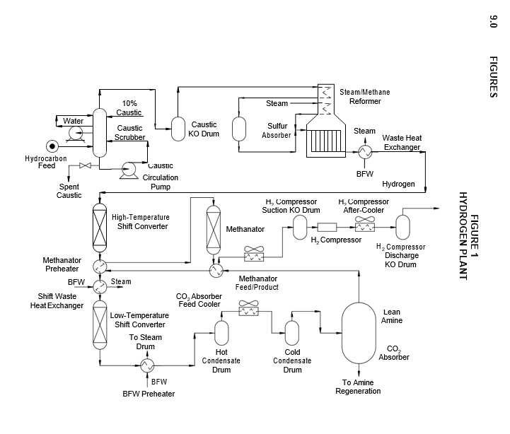
- The purpose of a hydrogen plant is to manufacture high–purity (95 to 99+ percent) hydrogen for such operations as hydrodesulfurization, hydrogenation, hydrocracking or petrochemical processing.
- A typical hydrogen manufacturing process (Figure 1) involves H2S scrubbing, reforming, carbon monoxide conversion, carbon dioxide removal and methanation. The hydrocarbon feed (natural gas, refinery gas, propane, butane and naphtha) is first scrubbed to prevent catalyst deactivation or poisoning. Depending on the type of feed and nature of sulfur contaminants, desulfurization methods can vary from ambient–temperature activated carbon absorption to high–temperature reaction with zinc oxide, to catalytic hydrogenation followed by zinc oxide treating. The desulfurized charge is mixed with superheated steam and reformed in catalyst– filled tubes at approximately 1100ºF to 1600ºF. The reformed gas consists of hydrogen, carbon monoxide, carbon dioxide and steam. This gas is cooled and passed through shift converters where the carbon monoxide is reacted with steam to form hydrogen and carbon dioxide. Almost all the carbon dioxide in the gas is removed by scrubbing with amine. Any remaining carbon monoxide and carbon dioxide in the hydrogen stream are reacted with hydrogen in the methanator and converted to methane.
- For details on carbon dioxide removal facilities refer to EP 10–1–14.
MAJOR MATERIALS AND CORROSION CONSIDERATIONS
- Alloy materials are required in various areas of the plant exposed to high–temperature and high pressure hydrogen to resist hydrogen attack. High–temperature hydrogen damage has been successfully controlled through the use of chromium–molybdenum steel and austenitic stainless steel, appropriately selected for resistance at a specific temperature and hydrogen partial pressure. Refer to EP 10–2–1.
- (*) Centrifugally cast HK–40 (0.38 to 0.45 percent C) material for reformer furnace tubes resists carburization, oxidation and creep. Other high alloy materials (HP–50, MO–RE 1 and 2, Manaurite 36 and 36S and other proprietary alloys) with improved creep strength may be considered, especially for design tube metal temperatures over 1850ºF. Use of these alloys is, however, subject to approval by the Owner’s Engineer. Materials specified for pigtails must be ductile enough for pinching off the process flow while in service.
- The cross section of the HK–40 tube shall exhibit a minimum of 50 percent columnar grain structure, with the grains originating at the outside diameter (OD) tube surface.
- Premature stress rupture of reformer tubes can occur as a result of localized overheating. Furnace tube temperatures shall be monitored by infrared or optical pyrometer to detect and correct overheating. Skin couples, visible from inspection doors, shall be installed on 4 percent of the tubes or a minimum of 4 couples per furnace, whichever is greater.
- Tubes shall be inspected by OD measurement, radiography, sampling and metallurgical examination to detect creep. Replace damaged components before creep rupture life is exhausted.
- (*) Incoloy 800 piping shall be used for reformer effluent streams operating above 1100ºF. Insulation jacketing on Incoloy 800 piping shall be stainless steel. Internally insulated Cr–Mo steel piping may be used subject to the Owner’s Engineer approval.
- Incoloy 800 (solution annealed) shall be used for the outlet pigtails and header. The outlet pigtails shall be of heavy wall construction, preferably Schedule 160. This material has the desired ductility to withstand thermal and mechanical stress; it also has good resistance to carburization, oxidation and creep.
- Type 304 stainless steel shall be used in hot and wet process gas or hot carbonated water. Water and carbon dioxide (CO2) form carbonic acid, which is highly corrosive to carbon steel.
- Lead content in reformer tubes shall be limited to less than 100 ppm. This will eliminate catastrophic carburization and oxidation of the HK–40 material.
CONSTRUCTION MATERIALS
- Recommended construction materials are presented in Table 1 through Table 3 for vessels, exchangers, piping and other equipment such as heaters and pumps.
- The materials of construction and corrosion allowances designated in this Practice are minimum requirements selected to provide satisfactory service in units operating at standard design conditions. Appropriate material specifications for piping components and equipment are covered in the Engineering Practices shown in Table 4.
- Post weld heat treatment (PWHT) and material hardness requirements for AES service shall be in accordance with EP 10–2–1 and EP 10–2–3.
CORROSION CONTROL METHODS
- The introduction of chlorides into the reformer tubes through hydrocarbon feed or steam system should be avoided.
- Caustic scrubbing facilities should be designed to prevent caustic carryover. Corrosion in the preheat train has been experienced as the result of carryover.
- Demineralized water shall be used for steam generation.
- The use of carbon steel or low–alloy steel in process gas containing CO2 shall be limited to temperatures above the gas dew point.
- Temperature–sensitive paints shall be maintained on the exterior of internally insulated lines and vessels to detect refractory failure.
- Corrosion probe connections shall be provided in the following locations:
- Cold condensate drum vapor space.
- Product gas line downstream from CO2 absorber.
- The boiler feedwater temperature shall be maintained above the process stream dew point to prevent condensation and formation of carbonic acid.
- If aqueous solutions containing chlorides or sulfur dioxide come in contact with reformer tube materials, stress corrosion cracking or accelerated corrosion may occur. Reformer tubes shall be protected from atmospheric contamination during shipment and storage.
8.0 TABLES
TABLE 1 CONSTRUCTION MATERIALS—VESSELS
| Equipment | Component | Materials |
|---|---|---|
| Caustic Scrubber | Shell | CS with 0.125 inch CA (1) |
| Caustic Scrubber | Internals | Type 410S |
| Caustic Knockout Drum | Shell | CS with 0.125 inch CA (1) |
| Sulfur Absorber | Shell | CS with 0.125 inch CA (1) |
| High–Temperature Shift Converter | Shell | 1–1/4Cr–1/2Mo with 0.125 inch CA |
| High–Temperature Shift Converter | Internals | 1–1/4Cr–1/2Mo |
| Low–Temperature Shift Converter | Shell | CS with 0.125 inch CA (1) |
| Low–Temperature Shift Converter | Internals | CS |
| Hot Condensate Drum and Cold Condensate Drum |
Shell | CS clad with 0.125 inch minimum Type 304 or overlaid with 0.187 inch minimum Type 304L |
| CO2 Absorber | Shell | CS with 0.125 inch CA (1) |
| CO2 Absorber | Trays | Type 410S |
| CO2 Absorber | Gas Inlet Nozzle | Type 304 |
| CO2 Absorber | Distributor | Type 304 |
| CO2 Absorber | Demister | Type 304 |
| Methanator | Shell | 1–1/4Cr–1/2Mo with 0.10 inch CA |
| Methanator | Internals | 1–1/4Cr–1/2Mo |
| H2 Compressor Suction and Discharge Knockout Drums |
Shell | CS with 0.125 inch CA |
Nomenclature: CS = Carbon Steel
CA = Corrosion Allowance
NOTES:
- Postweld heat treat vessel.
- Vessel to be postweld heat treated. Hardness of welds and heat–affected zones and PWHT requirements shall be in accordance with EP 10–2–1 and EP 10–2–3.
TABLE 2
CONSTRUCTION MATERIALS—EXCHANGERS
| Equipment | Component | Materials |
|---|---|---|
| Reformer Waste Heat Exchanger | Shell | CS with 0.125 inch CA |
| Reformer Waste Heat Exchanger | Inlet Channel | 1–1/4Cr–1/2Mo with 0.125 inch CA and Refractory Lined (1) |
| Reformer Waste Heat Exchanger | Outlet Channel | 1–1/4Cr–1/2Mo with 0.125 inch CA (1) |
| Reformer Waste Heat Exchanger | Tubesheet | 1–1/4Cr–1/2Mo with 0.125 inch CA (1) |
| Reformer Waste Heat Exchanger | Tubes | 1–1/4Cr–1/2Mo with Incoloy 800 ferrules (1) |
| Shift Waste Heat Exchanger | Shell | CS with 0.125 inch CA |
| Shift Waste Heat Exchanger | Channel | 1–1/4Cr–1/2Mo with 0.125 inch CA (1) |
| Shift Waste Heat Exchanger | Tubesheet | 1–1/4Cr–1/2Mo with 0.125 inch CA (1) |
| Shift Waste Heat Exchanger | Tubes | CS (1) |
| Methanator Preheater | Shell | 1–1/4Cr–1/2Mo with 0.125 inch CA (1) |
| Methanator Preheater | Channel | 1–1/4Cr–1/2Mo with 0.125 inch CA (1) |
| Methanator Preheater | Tubesheet | 1–1/4Cr–1/2Mo with 0.125 inch CA (1) |
| Methanator Preheater | Tubes | 1–1/4Cr–1/2Mo (1) |
| Boiler Feedwater Preheater | Shell | CS with 0.125 inch CA |
| Boiler Feedwater Preheater | Channel | CS clad with 0.125 minimum Type 304 (2) |
| Boiler Feedwater Preheater | Tubesheet | Type 304 with 0.05 inch CA (2) |
| Boiler Feedwater Preheater | Tubes | Type 304 (3) |
| CO2 Absorber Feed Cooler | Header | Type 304 with 0.05 inch CA (2) |
| CO2 Absorber Feed Cooler | Tubes | Type 304 |
| Methanator Feed/Product | Shell | 1–1/4Cr–1/2Mo with 0.125 inch CA (4) |
| Methanator Feed/Product | Channel | 1–1/4Cr–1/2Mo with 0.125 inch CA |
| Methanator Feed/Product | Tubesheet | 1–1/4Cr–1/2Mo with 0.125 inch CA |
| Methanator Feed/Product | Tubes | 1–1/4Cr–1/2Mo. |
| Product Gas Cooler and H2 Compressor After–Cooler | Header | CS with 0.125 inch CA |
| Product Gas Cooler and H2 Compressor After–Cooler | Tubes | CS |
Nomenclature: CS = Carbon Steel
CA = Corrosion Allowance
NOTES:
- (*) Materials are selected and based on general cases and will depend on design temperature and hydrogen partial pressure. Consult with the Owner’s Engineer to ensure that materials selected contain satisfactory resistance to hydrogen attack. Refer to EP 10–2–1.
- Use CS + 0.125 inch CA if the temperature of the process stream is above the dew point.
- Use carbon steel tubes if the temperature of the process stream is above the dew point.
(3) Use CS in place of 2 1/4Cr–1/2Mo steel if the shell–side stream temperature does not exceed 500oF.
TABLE 3
CONSTRUCTION MATERIALS—PIPING COMPONENTS AND OTHER EQUIPMENT
| Equipment | Component | Materials |
|---|---|---|
| Reformer Feed Line | Pipe (Metal Temperature < 500F) | CS with 0.125 inch CA |
| Reformer Feed Line | Pipe ( > 500F and < 850F) | 1–1/4Cr–1/2Mo with 0.125 inch CA (1) |
| Reformer Feed Line | Pipe ( > 850F) | 2–1/4Cr–1/2Mo with 0.10 inch CA (1) |
| Reformer Effluent Line (From Reformer Furnace to CO2 Absorber) | Pipe (Metal Temperature < Dew Point) | Type 304 with 0.05 inch CA |
| Reformer Effluent Line (From Reformer Furnace to CO2 Absorber) | Pipe (Dew Point to 850 F) | 1–1/4Cr–1/2Mo with 0.125 inch CA (1) |
| Reformer Effluent Line (From Reformer Furnace to CO2 Absorber) | Pipe ( > 850 F and < 1100 F) | 2–1/4CR–1/2Mo with 0.125 inch CA (1) |
| Reformer Effluent Line (From Reformer Furnace to CO2 Absorber) | Pipe ( > 1100 F) | Incoloy 800 with 0.05 inch CA or 2– 1/4Cr–1/2Mo with 0.125 inch CA internally insulated (2) |
| Product Gas Line (From CO2 Absorber) | Pipe (Metal Temperature < 500F) | CS with 0.125 inch CA |
| Product Gas Line (From CO2 Absorber) | Pipe ( > 500F) | 1–1/4Cr–1/2Mo with 0.125 inch CA (1) |
| Steam Lines | Pipe | CS with 0.125 inch CA |
| Valves in Carbon Steel Lines | Body | CS with 0.125 inch CA |
| Valves in Carbon Steel Lines | Trim | 12 Cr/Stellite |
| Valves in 2–1/4Cr–1/2Mo Steel Lines | Body | 2–1/4Cr–1/2Mo with 0.125 inch CA |
| Valves in 2–1/4Cr–1/2Mo Steel Lines | Trim | 12 Cr/Stellite |
| Valves in 1–1/4Cr–1/2Mo Steel Lines | Body | 1–1/4Cr–1/2Mo with 0.125 inch CA |
| Valves in 1–1/4Cr–1/2Mo Steel Lines | Trim | 12 Cr/Stellite |
| Valves in Type 304 Lines | Body | Type 304 with 0.05 inch CA |
| Valves in Type 304 Lines | Trim | Type 304/Stellite |
TABLE 3 (CONTINUED)
CONSTRUCTION MATERIALS—PIPING COMPONENTS AND OTHER EQUIPMENT
| Equipment | Component | Materials |
|---|---|---|
| Steam/Methane Reformer Heater | Process Stream Convection Section (Metal Temperature < 500 F) | CS with 0.125 inch CA |
| Steam/Methane Reformer Heater | Process Stream Convection Section (> 500 F and < 850 F) | 1–1/4Cr–1/2Mo with 0.125 inch CA (1) |
| Steam/Methane Reformer Heater | Process Stream Convection Section (> 850 F and < 1100 F) | 2–1/4Cr–1/2Mo with 0.125 inch CA (1) |
| Steam/Methane Reformer Heater | Process Stream Convection Section (> 1100 F) | Type 304H with 0.05 inch CA (1) |
| Steam/Methane Reformer Heater | Steam Convection Section (Metal Temperature < 800 F) | CS with 0.125 inch CA |
| Steam/Methane Reformer Heater | Steam Convection Section (> 800 F and < 900 F) | 1–1/4Cr–1/2Mo with 0.05 inch CA |
| Steam/Methane Reformer Heater | Steam Convection Section (> 900 F) | 2–1/4Cr–1/2Mo with 0.05 inch CA |
| Steam/Methane Reformer Heater | Radiant Section | HK–40 (0.38 to 0.45 C) (3) |
| Steam/Methane Reformer Heater | Outlet Pigtails and Manifolds | Incoloy 800 (solution annealed) |
| Caustic Circulation and Wash Water Pump | Casing | CS with 0.10 inch CA |
| Caustic Circulation and Wash Water Pump | Impeller | CI (4) |
| Boiler Feed Water and BFW Circulation Pump | Casing | 12% Cr with 0.10 inch CA |
| Boiler Feed Water and BFW Circulation Pump | Impeller | 12% Cr |
| H2 Compressor | CS and low–alloy steel (consult the Owner’s Engineer) |
Nomenclature: CS = Carbon Steel
CA = Corrosion Allowance Cl = Cast Iron
NOTES:
- (*) Materials selected are based on general cases and will depend on design temperature and hydrogen partial pressure. Refer to EP 10–2–1, and consult with the Owner’s Engineer, to ensure that the materials selected contain satisfactory resistance to hydrogen attack.
- Internally insulated 2–1/4Cr–1/2 Mo steel piping shall have an internal Incoloy 800 liner.
- (*) Other creep–resistant alloys may be used subject to approval by Owner’s Engineer.
- In multi–stage pumps, use CS impellers.
TABLE 4
MATERIAL SPECIFICATIONS AND NDE REQUIREMENTS
| Piping Component or Equipment Type | Engineering Practice |
|---|---|
| Piping components and valve trim Pressure vessels & heat exchangers Pressure vessels – Internals Atmospheric storage tanks Low pressure storage tanks Pressure storage spheres |
EP 5–1–1 EP 7–1–1 EP 7–2–1 EP 9–1–1 EP 9–2–1 EP 9–4–1 |
© 2026 Inflection Point Engineering, LLC. All rights reserved. The content of this page — including calculation methods, reference data, written analysis, interactive tools, and source code — is the intellectual property of Inflection Point Engineering, LLC and is protected under applicable copyright, trademark, and trade secret laws. Unauthorized reproduction, redistribution, modification, or derivative use in whole or in part is prohibited without prior written consent.
Disclaimer. This material is provided for informational and educational purposes only and does not constitute professional engineering advice. Calculations, reference data, and methodologies are based on published standards and accepted engineering practice but are not a substitute for engineering judgment, site-specific analysis, or review by a licensed Professional Engineer. Inflection Point Engineering, LLC makes no warranties, express or implied, regarding the accuracy, completeness, or fitness for a particular purpose of any content presented here, and shall not be liable for any direct, indirect, incidental, or consequential damages arising from its use. Users assume all risk associated with applying this content to real-world design, operations, or decisions.
© 2026 Inflection Point Engineering, LLC. All rights reserved.