 Section 10 — Material Requirements
Sulphur Plants
IPE Engineering Practice IPE-EP-10-1-15
Document number: IPE-EP-10-1-15 · Section: 10 — Material Requirements
SCOPE
- This Practice provides information for the selection of materials for sulfur plants. This Practice encompasses the modified Claus process and several of its variations.
- This Practice is for guidance purposes and deviation per EP 1–1–3 is not required.
- An asterisk (*) indicates that a decision by the Owner or Owner’s Engineer is required, or that additional information is to be furnished by the Purchaser.
2.0 REFERENCES
The latest edition of the following standards and publications are referred to herein.
STANDARDS AND PUBLICATIONS
| Engineering Practices | Engineering Practices |
|---|---|
| EP 1–1–3 | Deviations to Engineering Practices |
| EP 5–1–1 | General Piping Design |
| EP 7–1–1 | Pressure Vessels |
| EP 7–2–1 | Pressure Vessel Internals |
| EP 9–1–1 | Atmospheric Storage Tanks |
| EP 9–2–1 | Low Pressure Storage Tanks |
| EP 9–4–1 | Pressure Storage Spheres |
| EP 10–2–1 | Material Requirements for Aggressive Environmental Services |
| EP 10–2–3 | Material Hardness Requirements |
DEFINITIONS
- Aggressive Environmental Service (AES) – Process services which result in material degradation such as cracking, scaling, blistering, and severe pitting and/or corrosion. Examples of such services are hydrogen service, wet hydrogen sulfide, cyanides, caustic, amine, and hydrofluoric acid. AES process fluid are defined in EP 10–2–1.
- Equipment – Each pump, compressor, product accumulator vessel, pressure relief device, valve, sampling connection system, open–ended valve or line, flange or other connector in VOC service, or devices or systems required by this Practice.
- Owner – Refining Company.
- Owner’s Engineer – A Refining Company appointed engineer.
GENERAL
- This Practice is to be used for projects when specifying construction materials for sulfur plants.
- The purpose of the sulfur plant is to recover sulfur from hydrocarbon streams or other available sources that contain hydrogen sulfide gases.
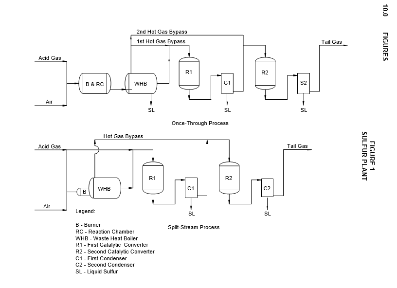
- The most commonly used process for sulfur recovery, the modified Claus process, is based on producing elemental sulfur by burning hydrogen sulfide under precisely controlled conditions. Subsequently, the gases are made to react in the presence of a suitable catalyst to recover an additional amount of sulfur. Sulfur vapor is formed in both the combustion and conversion reactions; cooling after each reaction condenses out most of the sulfur formed. The basic variations of the process (see Figure 1) are governed by the reheating methods used: hot gas bypass, in–line burners, and indirect fired heaters. Proprietary alternatives of the modified Claus process are also available. Generally, a knockout pot is added to remove entrained water and hydrocarbons from the acid gas feed–stream.
MAJOR MATERIALS AND CORROSION CONSIDERATIONS
- Sulfur recovery units generally are built of carbon steel. Areas exposed to high temperatures may be protected by the use of refractory linings or stainless steel.
- Common materials problems are:
- Sulfidation due to excessive temperatures.
- Corrosion as a result of solutions of corrosive gases in moisture condensed from process streams.
- Deterioration of refractory linings caused by improper materials selection or thermal shock.
- Corrosion by high–temperature sulfidation can be avoided by the use of internal refractory linings to lower metal temperatures to below 575ºF and, to a much lesser extent, by the use of either alloy or water–cooled surfaces.
- Corrosion that results from water condensation on the process side of exterior metal surfaces can be avoided by the use of external insulation to maintain metal temperatures above the water dew point of the process gases. Care should be taken not to raise the metal temperature over 575ºF, at which point sulfidation will occur.
- Refractory deterioration can be reduced by:
- Using proper cooling and heating rates to eliminate the danger of thermal shock.
- Maintaining the temperature within materials capabilities for all or any one of the courses of fire brick, insulating fire brick, or castables.
- Assuring that the refractory is chemically suitable to withstand the reducing atmosphere and acidic nature of the process.
CONSTRUCTION MATERIALS
- Recommended construction materials are presented in Table 1 through Table 4 for vessels, exchangers, piping, and other equipment such as heaters and pumps.
- The materials of construction and corrosion allowances designated in this Practice are minimum requirements selected to provide satisfactory service in units operating at standard design conditions. Appropriate material specifications for piping components and equipment are covered in the Engineering Practices listed in Table 5.
- Post weld heat treatment (PWHT) and material hardness requirements for AES service shall be in accordance with EP 10–2–1 and EP 10–2–3.
CORROSION CONTROL METHODS
- Metal surfaces exposed to process streams and condensed moisture shall be insulated or steam jacketed to maintain metal surface temperatures above the process stream dew point. Steam tracing is not adequate.
- All major carbon steel flow lines that may be exposed to temperatures over 575ºF shall be cement or refractory lined; alternatively, Type 321 or 347 stainless steel lines can be used.
- Horizontal sulfur condensers that have a vapor disengaging section shall be used to insure that all tubes are covered by water. Steam pockets may form in horizontal condensers, preventing rapid heat transfer and resulting in high–temperature sulfiding of the upper tube tips and the top of the tubesheet.
- The proper refractory drying procedure shall be followed to prevent refractory deterioration and exposure of the carbon steel reactor or piping surfaces to a high–temperature sulfiding environment. Check with the refractory supplier for the recommended drying procedure.
MATERIALS CONSIDERATIONS DURING FABRICATION
- (*) Where exposure to hydrogen sulfide, water, and air is probable, stabilized grades of stainless steel, Type 321 or Type 347, shall be used in welded construction to minimize the possibility of intergranular corrosion. The Owner’s Engineer may specify 304L or 316L for some applications.
- Tubes in the waste heat boiler and condensers shall be seal welded to the tubesheet.
9.0 TABLES
TABLE 1
CONSTRUCTION MATERIALS-VESSELS
| Equipment | Component | Materials |
|---|---|---|
| Acid Gas Knockout Pot | Shell | CS with 0.125 inch CA (1) |
| Catalytic Converters | Shell | CS refractory lined (2) |
| Catalytic Converters | Burner Tips | Type 310 |
| Catalytic Converters | Catalyst Screens | Type 310 |
| Catalytic Converters | Catalyst Supports | CI (3) |
| Settler | Shell | CS clad with 0.0625 inch minimum Type 410S |
| Tail gas knockout pot (if used) |
Shell | CS with 0.125 inch CA |
Nomenclature: CS = carbon steel
CA = corrosion allowance CI = cast iron
NOTES:
- Vessel to be stress relieved. Hardness for welds and heat–affected zones shall be in accordance with EP 10–2–1 and EP 10– 2–3. Stainless should be considered.
- For temperatures below 575oF, refractory lining is not required.
- At temperatures over 800oF, Type 310 stainless steel shall be used.
TABLE 2
CONSTRUCTION MATERIALS-EXCHANGERS
| Equipment | Component | Materials |
|---|---|---|
| Condensers | Shell | CS with 0.125 inch CA |
| Condensers | Channel | CS with 0.125 inch CA |
| Condensers | Tubesheet | CS with 0.125 inch CA |
| Condensers | Tubes | CS – seamless |
| Waste heat boiler | Shell | CS with 0.125 inch CA |
| Waste heat boiler | Vestibule | CS refractory lined (1) |
| Waste heat boiler | Tubesheets | CS refractory lined (1) |
| Waste heat boiler | Tubes | CS – seamless (2) |
Nomenclature: CS = carbon steel
CA = corrosion allowance
NOTES:
- For temperatures below 575oF, refractory lining is not required.
- If tube inlet metal temperature is over 575oF, ceramic ferrules shall be used.
TABLE 3
CONSTRUCTION MATERIALS—PIPING
| Equipment | Component | Materials |
|---|---|---|
| Line from Sulfur Reactor to Waste Heat Boiler | Pipe | CS refractory lined (1) |
| Hot Bypass | Pipe (< 575 F) | CS with 0.125 inch CA |
| Hot Bypass | Pipe ( > 575 F) | Type 321 or Type 347 with 0.0625 inch CA or CS refractory lined |
| H2S Transfer Lines | Pipe | CS with 0.125 inch CA (2) |
| Remaining Lines | Pipe | CS with 0.125 inch CA (3) |
Nomenclature: CS = carbon steel
CA = corrosion allowance
NOTES:
- For temperatures below 575oF, refractory lining is not required; however, lines must be maintained above dew point.
- Lines must be maintained above stream dew point.
- Hardness for welds and heat–affected zones for piping exposed to moist hydrogen sulfide (more than 50 ppm H2S) shall be in accordance with EP 10–2–1 and EP 10–4–1.
TABLE 4
CONSTRUCTION MATERIALS—OTHER EQUIPMENT
| Equipment | Component | Materials |
|---|---|---|
| Sulfur Reactor Furnace | Shell | CS refractory lined (1) |
| Indirect Fuel Gas Heater (if used) | Shell (< 575 F) | CS with 0.125 inch CA |
| Indirect Fuel Gas Heater (if used) | Shell ( > 575 F) | Type 321 or Type 347 with 0.05 inch CA |
| In–Line Acid Gas Burner (if used) | Burner | CS refractory lined (1) |
| Boiler Feedwater Pump | Casing | CS with 0.125 inch CA |
| Boiler Feedwater Pump | Impeller | CI |
| Sulfur Transfer Pumps | Casing | CS with 0.125 inch CA |
| Sulfur Transfer Pumps | Impeller | CI |
| Liquid Sulfur Pit | Shell | Acid Resistant Concrete |
| Liquid Sulfur Pit | Cover | Aluminum (2) |
| Sulfur Storage Tanks | Shell | CS with 0.10 inch CA (3)(4) |
Nomenclature: CS = carbon steel
CA = corrosion allowance CI = cast iron
NOTES:
- For temperatures below 575oF, refractory lining is not required.
- The aluminum cover shall be kept free from moisture.
- No copper or copper–bearing alloys shall be used.
- On storage tanks where the carbon steel dip hatch cover is subject to heavy corrosion due to presence of moisture, use of aluminum should be considered.
TABLE 5
MATERIAL SPECIFICATIONS AND NDE REQUIREMENTS
| Piping Component or Equipment Type | Engineering Practice |
|---|---|
| Piping components and valve trim Pressure vessels & heat exchangers Pressure vessels – Internals Atmospheric storage tanks Low pressure storage tanks Pressure storage spheres |
EP 5–1–1 EP 7–1–1 EP 7–2–1 EP 9–1–1 EP 9–2–1 EP 9–4–1 |
© 2026 Inflection Point Engineering, LLC. All rights reserved. The content of this page — including calculation methods, reference data, written analysis, interactive tools, and source code — is the intellectual property of Inflection Point Engineering, LLC and is protected under applicable copyright, trademark, and trade secret laws. Unauthorized reproduction, redistribution, modification, or derivative use in whole or in part is prohibited without prior written consent.
Disclaimer. This material is provided for informational and educational purposes only and does not constitute professional engineering advice. Calculations, reference data, and methodologies are based on published standards and accepted engineering practice but are not a substitute for engineering judgment, site-specific analysis, or review by a licensed Professional Engineer. Inflection Point Engineering, LLC makes no warranties, express or implied, regarding the accuracy, completeness, or fitness for a particular purpose of any content presented here, and shall not be liable for any direct, indirect, incidental, or consequential damages arising from its use. Users assume all risk associated with applying this content to real-world design, operations, or decisions.
© 2026 Inflection Point Engineering, LLC. All rights reserved.