 Section 10 — Material Requirements
Amine Plants
IPE Engineering Practice IPE-EP-10-1-14
Document number: IPE-EP-10-1-14 · Section: 10 — Material Requirements
SCOPE
- This Practice provides information for the selection and use of materials in Amine Plants. Operational and design variables which can degrade equipment are presented.
- This Practice is for guidance purposes and deviation per EP 1–1–3 is not required.
- An asterisk (*) indicates that a decision by the Owner or Owner’s Engineer is required, or that additional information is to be furnished by the Purchaser.
2.0 REFERENCES
The latest edition of the following standards and publications are referred to herein.
STANDARDS AND PUBLICATIONS
| Engineering Practices |
|---|
| EP 1–1–3 Deviations to Engineering Practices EP 5–2–1 Selection of Piping Components and Materials EP 5–3–1 Valve Design and Selection Criteria EP 7–2–2 Fractionating Tray and Tower Packing EP 8–1–3 Tube Bundle Replacement EP 8–1–4 Air Cooled Exchangers EP 10–2–1 Material Requirements for Aggressive Environmental Services EP 10–2–3 Material Hardness Requirements |
| API |
| RP 945 Guidelines for Avoiding Corrosion and Cracking in Amine Units |
DEFINITIONS
- Amine – Organic compounds having amino functional groups which provide chemical reactivity and utility as a curative for epoxy and other resins.
- Amine Plant – An organic compound which has the general formula RxNH2 where R is an alkyl or aryl group. In this guideline, Amine will refer to an aldanolamine such as MEA, MDEA, DEA, DGA, etc.
- Heat Stable Salts – Reaction Products of amine with stronger acids than H2S or CO2. Examples would include thiosulfate and thiocyanates.
- Lean Amine – Amine that has been regenerated by steam stripping and is not heavily loaded with acid gas components. The main criteria is regeneration of the amine so that the H2S content is below 40 grains per gallon.
- Owner – Refining Company.
- Owner’s Engineer – A Refining Company appointed engineer.
- Rich Amine – Amine that is heavily loaded with acid gas.
4.0 AMINE PLANT DESCRIPTION
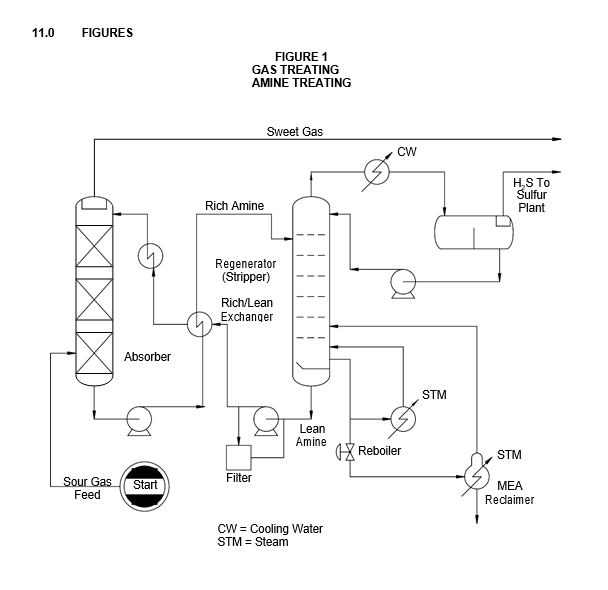
An amine system absorbs hydrogen sulfide and carbon dioxide from various gases to meet a specification. For example, refinery fuel gas is treated to prevent air pollution and corrosion when the gases are burned. The targeted specification is typically 10 grains per hundred standard cubic foot for fuel gas. Figure 1 displays a simplified flow diagram of the basic operation. Sour feed gas containing H2S and/or CO2 will nearly always enter the plant through a scrubber (KO drum) to remove any free liquid. The sour gas enters near the bottom of a tower in which it contacts the lean amine solvent which cascades downward. The amine absorbs the acid gas components from the sour gas. The sweetened gas product exits at the top of the tower. Rich amine solution flows from the bottom of the absorber or contactor tower to the rich amine flash drum for removal of dissolved hydrocarbons. The rich amine is then pumped and preheated in the rich/lean exchanger and sent to the regenerator tower where it is reactivated. In the regenerator, hydrogen sulfide and/or carbon dioxide are driven off by heat and stripping steam. The lean amine from the bottom of the regenerator tower is cooled by interchange of heat with the rich amine in the cross exchanger and then is pumped through the lean amine cooler and the top of the absorber continuing the cycle.
AMINE SOLUTION DESCRIPTIONS
- Typical amine solutions include:
- Monethanolamine, MEA
- Diethanolamine, DEA
- Methyldiethanolamine, MDEA
- Diglycolamine, DGA
- (2–2 Hydroxy–ethylamine)
- 2–(2–amino–ethoxy) ethanol
- Diisopropanolamine, DIPA
- Combinations of the above with additives.
- An important feature of the type of amine used is the molecular weight and selectivity of the amine for particular acidic species. Since acid gases and amines react on an equivalent weight, rather than a weight basis, MEA with a 61.1 equivalent weight has an advantage over DEA with a 105.1 equivalent weight, DGA with 105.1 and DIPA with a 133.2.
- Because MEA is a stronger base than most alkanol amines, it does an excellent job of gas purification. A disadvantage is that MEA reacts non–regeneratively with carbonyl sulfide and has a relatively high vapor pressure, which contributes to losses. One advantage of MEA is that it can be regenerated from a heat stable salt.
- Typically, the recommended concentration of aqueous amine solutions used are shown in Table 5.
- Higher concentration of solution increases the bottom temperatures of the regenerator and emphasis on loss control becomes mandatory. High amine concentrations are used when the existing equipment does not achieve the desired treatment capacity. Initial unit design should be based on the lower concentration of amine.
MATERIALS OF CONSTRUCTION
- Recommended materials of construction are presented in Table 1 through Table 3. The tables provide material recommendations for vessels, exchangers, piping, and other equipment such as pumps.
- In designing an amine plant the most effective means of controlling corrosion is to avoid the undersizing of equipment.
- PWHT requirements for materials in amine services are covered in EP 10-2-1.
VARIABLES AFFECTING CORROSION RATE
- Amine Strength
The concentrations presented in paragraph 5.4 of this Practice must be closely maintained in order to control corrosion in the system.
- Acid Gas Loading
The recommended total acid gas loading for rich amine solution must be maintained in order to control the rich amine corrosion rate. For MEA the recommended limit of acid gas loading is
0.35 moles of acid gas per mole of MEA. An increase in loading from 0.35 to 0.37 would be expected to cause a 100 percent increase in corrosion rate. For DEA the recommended maximum acid gas loading is 0.3 to 0.4 moles acid gas/mole DEA.
- Stripper Pressure
Stripper pressures should be maintained at the lowest level practical in order to minimize the regeneration temperature. Amines tend to degrade with temperature and the degradation products accelerate corrosion. The stripped acid gases should be effectively cooled as they come off of the regenerator to reduce stripper bottoms pressure.
- Regeneration Temperature
When stripping acid gases from the rich amine solution, metal temperatures in excess of 300ºF should not be used. High metal skin temperatures, in addition to degrading amine, can cause high reboiler tube corrosion rates by flashing acid gases. Low pressure (40–50 psia) desuperheated steam should not be used.
- Corrosive Contaminants
- Raw gas contaminants and high temperatures tend to degrade amines into corrosive chelating agents. Proper selection of the amine used, heat control and reducing contaminates such as hydrocyanic acid (HCN) in the feed will permit corrosion control.
- Heat stable salts are reaction products of amine with stronger acids than H2S or CO2 (such as formic or acetic acid). They do not break down at the prescribed regeneration temperature. A typical heat stable salt is thiosulfate which is primarily formed by oxygen in the system. Care must be taken to not operate the regeneration at a higher temperature in an effort to remove thiosulfate and alkali sulfides which would be identified as H2S in most analytical procedures.
- Oxygen leakage into the system causes high corrosion rates and should be prevented by blanketing storage tanks and surge vessels with inert gas and maintaining a tight system.
- Liquid hydrocarbons cause foaming and fouling in the system. Proper cooling and water scrubbing equipment should be provided to maintain a gas stream without entrained liquid hydrocarbon.
- Solids in the amine cause erosion/corrosion and should be maintained at very low levels with appropriate corrosion control and filtration. A precoat filter using diatomaceous earth, located in the lean amine circuit provides efficient filtration.
CORROSION CONTROL EQUIPMENT/DESIGN
- To obtain low corrosion rates in the amine system it is important to maintain a gas feed which contains the lowest amount of hydrocarbon liquid and corrosive contaminants. Dry gas water scrubbing can be used where HCN is expected.
- The amine solution should not contain solids greater than 0.01 weight percent. A diatomaceous precoat–type filter should be maintained to provide a clear solution. A system for recovering the amine from the filter is critical for an environmentally acceptable operation.
- Piping and equipment should be sized to maintain amine velocities less than three feet per second. Control valves should be oversized to reduce high velocity two–phase flow.
- Rich amine should exit at the top of exchangers to avoid gas entrapment. The rich amine flash drum pump control valve should be located downstream of the rich amine exchanger and preferably at the inlet to the stripper to avoid vaporization in the rich amine exchanger and stripper feed line. Multiple inlets can be used to avoid stagnation in the reboiler and reclaimer (if used). If a reclaimer is in the system, multiple vapor outlets can be used to eliminate acid gas stagnation. Tubes in the reboiler and, if applicable, the reclaimer should have a wide tube spacing and should be covered with no less than six inches of liquid when in operation.
- Since reclaimers have not been successful in DEA solutions to reduce corrosive contaminants, a “deep bed” activated carbon filtration is used. The activated carbon filter should be installed downstream of the mechanical filter(s) to avoid blockage. Cross–sectional area of the filter would permit about ten gallons per minute per square foot, with a bed depth of about seven feet. A large carbon particle size of 4x10 mesh combined with a low bulk density carbon is effective. Typical bed life would be about two to six months before regeneration with 40 psi steam is necessary. The filter would be expected to reduce corrosion and foaming if installed and operated properly.
- Another method to reduce heat stable salts in DEA solution is to add soda ash solution directly to the system to maintain less than 0.2% heat stable salts.
RECOMMENDED TESTING
- In order to maintain corrosion control in the system frequent analytical testing is required:
- Amine strength
- Acid gas loading of rich amine from each absorber
- Acid gas loading of the lean amine
- Heat stable salts
- Iron content of the overhead condensate.
- Each test should be performed at a frequency that is required in order to maintain system control.
10.0 TABLES
TABLE 1
CONSTRUCTION MATERIALS—VESSELS
| EQUIPMENT | COMPONENT | MATERIALS |
|---|---|---|
| Liquid Contactor | Shell | Killed CS with 0.125 inch CA (2) |
| Liquid Contactor | Internals | Type 410S |
| Liquid Contactor | Trays | Type 410S |
| Liquid Contactor | Coalescer | Type 304 |
| Gas Absorber | Shell | Killed CS with 0.125 inch CA (2) |
| Gas Absorber | Internals | Type 410S |
| Gas Absorber | Trays | Type 410S |
| Gas Absorber | Coelescer | Type 304 |
| Liquid Contactor Overhead Accumulator |
Shell | Killed CS with 0.15 inch CA (2) |
| Rich Amine Flash Drum | Shell | Killed CS with 0.15 inch CA (2) |
| Rich Amine Flash Drum | Demister | Type 304 |
| Amine Regenerator (3) | Shell | Killed CS with 0.15 inch CA (2), (4), (5) |
| Amine Regenerator (3) | Internals | Type 304 |
| Amine Regenerator (3) | Trays | Type 410S |
| Amine Regenerator (3) | Demister | Type 304 |
| Amine Regenerator Reflux Accumulator |
Shell | Killed CS with 0.15 inch CA (2) |
Nomenclature: CS = Carbon Steel
CA = Corrosion Allowance.
NOTES:
- Plants handling gases containing less than 1 percent hydrogen sulfide in the total acid gas portion of the feed gas are regarded as carbon dioxide plants. In this table materials selection is the same for both H2S and CO2 amine systems.
- Vessels shall be Postweld heat treated per EP 10–2–1. Hardness of welds and heat–affected zones (HAZ) shall be in accordance with EP 10–2–3.
- Some pitting of carbon steel amine regenerator walls has been observed. This pitting has been attributed to direct liquid impingement on the walls or galvanic coupling. Baffles installed in columns at impingement areas have alleviated impingement and anodes reduce galvanic coupling in wetted areas.
- Line amine regenerator nozzles with Type 304L stainless steel at reboiler inlets and reclaimer inlets. Line amine regenerator flash zone with Type 304L stainless steel.
- Line amine regenerator shell with Type 304L stainless steel at feed tray and above in sulfinol systems only.
TABLE 2
CONSTRUCTION MATERIALS—EXCHANGERS
| EQUIPMENT | COMPONENT | MATERIALS |
|---|---|---|
| Lean Amine Coolers: Air Cooler | Header | CS with 0.125 inch CA |
| Lean Amine Coolers: Air Cooler | Tubes | CS |
| Lean Amine Coolers:Water Cooler (2) | Shell | CS with 0.125 inch CA (4) |
| Lean Amine Coolers:Water Cooler (2) | Channel | CS with 0.125 inch CA |
| Lean Amine Coolers:Water Cooler (2) | Tubesheets | CS with 304 or 316SS Cladding |
| Lean Amine Coolers:Water Cooler (2) | Tubes | E–Brite 26–1 (3) |
| Rich–Lean Amine Exchangers | Shell | Killed CS with 0.25 inch CA (4) |
| Rich–Lean Amine Exchangers | Channel | Killed CS with 0.25 inch CA (4) |
| Rich–Lean Amine Exchangers | Tubes | E–Brite, 430SS, Titanium, Alloy 2205 or 316SS (5) |
| Amine Regenerator Overhead Condenser | Header | Killed CS + 0.25 inch CA (4) |
| Amine Regenerator Overhead Condenser | Tubes | Al 3003 or Al 3004 (6) or Titanium (8) or 304 |
| Amine Regenerator Reboiler, Amine Reclaimer | Shell | Killed CS with 0.20 inch CA (4) |
| Amine Regenerator Reboiler, Amine Reclaimer | Channel | Killed CS with 0.20 inch CA (4) |
| Amine Regenerator Reboiler, Amine Reclaimer | Tubesheets | Killed CS with 0.20 inch CA (4) |
| Amine Regenerator Reboiler, Amine Reclaimer | Tubes | CS (0.109 inch minimum wall thickness) (7) |
Nomenclature: CS = Carbon Steel
CA = Corrosion Allowance Al = Aluminum
SS = Stainless Steel
NOTES:
- Plants handling gases containing less than 1 percent hydrogen sulfide in the total acid gas portion of the feed gas are regarded as carbon dioxide plants. In this table materials selection for CO2 and H2S amine plants are the same.
- (*) Verify compatibility of heat exchanger materials with quality of available cooling water by consulting with Owner’s Engineer.
- CS tubes may be used if the quality of treated water is acceptable.
- Exchanger shells, channels, and headers shall be postweld heat treated per EP 10–2–1. Hardness of welds and heat affected zones (HAZ) shall be in accordance with EP 10–2–3.
- Use E–brite or duplex stainless steel tubes if tube surface temperatures exceed 250F or other alloys tested do not provide suitable service life. Temperatures above 300oF are not permitted.
- Velocity at inlet ends of aluminum tubes shall be 50 fps maximum.
- If skin temperature exceeds 250oF and/or carbon steel service life is unacceptable use AL6XN or E–brite with 304 or 316SS clad tubesheets.
- Ti or Ti clad header shall be used with Ti tubes.
TABLE 3
CONSTRUCTION MATERIALS—PIPING COMPONENTS AND OTHER EQUIPMENT
| EQUIPMENT | COMPONENT | MATERIALS |
|---|---|---|
| Between Pressure Control Valve and Amine Regenerator (2)(3) | Pipe | Type 316L with 0.0625 inch CA |
| Between Rich–Lean Exchangers, Amine Regenerator, Regenerator Reboiler and Regenerator Reclaimer, Regenerator Over– head to Condensers (2)(3) |
Hot Amine Pipe | CS with 0.125 inch CA ((5), (6) |
| Remaining Amine Piping (2)(3) | Amine Pipe | CS + 0.125 inch CA |
| H2S Transfer Lines and Supporting Equipment (2)(3) | Pipe | (7) |
| Amine–Containing Streams | Valve Body (< 200F and P < 100 psi) |
CS with 0.125 inch CA |
| Amine–Containing Streams | Valve Trim Body (< 200F and P < 100 psi) |
Type 316 |
| Amine–Containing Streams | Valve Body (< 200F or P < 100 psi) |
Type 316 |
| Amine–Containing Streams | Valve Trim Body (< 200F or P < 100 psi) |
Hastelloy C, titanium (no stellited coatings permitted) |
Nomenclature: CS = Carbon Steel
CA = Corrosion Allowance
NOTES:
- Plants handling gases containing less than 1 percent hydrogen sulfide in the total acid gas portion of the feed gas are regarded as carbon dioxide plants.
- Hardness of carbon steel welds and heat–affected zones (HAZ) exposed to moist H2S shall be in accordance with EP 10–2–3.
- Postweld heat treat all carbon steel amine piping operating at temperatures of 150F and above, per EP 10–2–1.
- In MEA systems, carbon steel piping may be used if Dow inhibitor, or equivalent, is employed.
- In sulfinol systems, Type 316L stainless steel (with 0.05 inch CA) shall be used if piping metal temperatures exceed 210F.
- In MEA and DEA (if the metal temperature exceeds 250oF) systems, use Type 316 and 0.0625 inch CA for rich amine line between rich–lean exchanger and pressure control valve, and for the line from reclaimer to regenerator tower.
- (*) Consult with the Owner’s Engineer.
TABLE 4
CONSTRUCTION MATERIALS—ROTATING EQUIPMENT
| EQUIPMENT | COMPONENT | MATERIALS |
|---|---|---|
| Lean Amine Pump | Casing | Casing: CS + 0.125 inch CA |
| Lean Amine Pump | Impeller | 12% Cr |
| Regenerator Reflux Pump | Casing | Casing: CS + 0.125 inch CA |
| Regenerator Reflux Pump | Impeller | 12% Cr |
NOTE:
(1) Plants handling gases containing less than 1 percent hydrogen sulfide in the total acid gas portion of the feed gas are regarded as carbon dioxide plants.
TABLE 5
AQUEOUS AMINE SOLUTION CONCENTRATIONS
| Solution | Recommended Concentration |
|---|---|
| MEA | 15% |
| MEA and diethanol glycol (Fluor process) (1) | 95% |
| DEA | 20–30% |
| DEA with corrosion inhibitor | 50% |
| Ucarsol HS101 (2) (inhibited MDEA) | 25–50% |
| DGA | 55% |
NOTES:
- Application limited to cold climates.
- Trademark of Union Carbide.
© 2026 Inflection Point Engineering, LLC. All rights reserved. The content of this page — including calculation methods, reference data, written analysis, interactive tools, and source code — is the intellectual property of Inflection Point Engineering, LLC and is protected under applicable copyright, trademark, and trade secret laws. Unauthorized reproduction, redistribution, modification, or derivative use in whole or in part is prohibited without prior written consent.
Disclaimer. This material is provided for informational and educational purposes only and does not constitute professional engineering advice. Calculations, reference data, and methodologies are based on published standards and accepted engineering practice but are not a substitute for engineering judgment, site-specific analysis, or review by a licensed Professional Engineer. Inflection Point Engineering, LLC makes no warranties, express or implied, regarding the accuracy, completeness, or fitness for a particular purpose of any content presented here, and shall not be liable for any direct, indirect, incidental, or consequential damages arising from its use. Users assume all risk associated with applying this content to real-world design, operations, or decisions.
© 2026 Inflection Point Engineering, LLC. All rights reserved.