 Section 9 — Storage Tanks
Pressure Storage Spheres
IPE Engineering Practice IPE-EP-9-4-1
Document number: IPE-EP-9-4-1 · Section: 9 — Storage Tanks
SCOPE
- This Practice covers requirements governing the design, fabrication, inspection and testing of storage spheres with a design pressure equal to or greater than 15 psig.
- Pressure storage spheres designed, fabricated, inspected and tested to this Practice shall comply with the ASME Code Section VIII, Divisions 1 or 2. Therefore, the general requirements of EP 7–1–1 are the basis of this Practice. Supplemental requirements particular to pressure storage spheres are cited directly in this Practice.
- Any deviation to this Practice must be approved by the procedure described in EP 1–1–3.
- An asterisk (*) indicates that a decision by the Owner’s Engineer or Owner is required, or that additional information is furnished by the Purchaser.
- A revision bar indicates all changes made to this Revision.
2.0 REFERENCES
The latest edition of the following standards and publications are referred to herein.
STANDARDS AND PUBLICATIONS
| Engineering Practices |
|---|
| EP 1–1–3 Deviations to Engineering Practices EP 3–5–3 Fixed Water Spray Fire Protection Systems EP 5–1–1 General Piping Design EP 7–1–1 Pressure Vessels EP 11–2–1 Fireproofing EP 11–3–4 Insulation Application - Storage Tanks and Spheres |
| ASME Codes |
| Sec VIIIPressure Vessels, Division 1 Sec VIIIPressure Vessels, Alternative Rules, Division 2 |
| APl Publications |
| Std 2508 Design and Construction of Ethane and Ethylene Installations Std 2510 Design and Construction of Liquefied Petroleum Gas (LPG) Installations |
DEFINITIONS
- Inspector - A Refining Company appointed engineer or inspector.
- Manufacturer - The recipient of a direct or indirect purchase order for materials and/or equipment. In this context, a direct order is one issued to a manufacturer by a contractor or the Owner. An indirect order is one issued to a manufacturer by a vendor (recipient of a direct order) for materials, fabricated components, or subassemblies.
- Owner - Refining Company.
- Owner’s Engineer - A Refining Company appointed engineer.
- Purchaser - The party placing a direct purchase order. The purchaser is the Owner’s designated representative.
4.0 DATA SHEET, DOCUMENTATION, AND PURCHASING REQUIREMENTS
The vessel data sheet, documentation and purchasing shall be in accordance with EP 7–1–1.
5.0 QUALITY ASSURANCE
The quality assurance program shall be in accordance with EP 7–1–1.
6.0 MATERIALS
Materials of construction for low pressure storage spheres shall be in accordance with EP 7–1–1.
DESIGN
- The design of pressure storage spheres shall be in accordance with EP 7–1–1 and the additional requirements of this Practice.
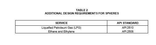
- In addition to the requirements of this Practice, spheres to be used in the services indicated in Table 2 shall also incorporate the design requirements stipulated in the associated APl standard.
- (*)Unless otherwise specified by the Owner’s Engineer, spheres with a design pressure greater than 15 psig shall be designed to be completely filled with water. A pneumatic test or a combination hydrostatic–pneumatic test shall not be used without approval of the Owner’s Engineer.
- (*)The height of the bottom of the sphere above finished grade shall be specified by the Owner’s Engineer. In no case shall this be less than 3 feet.
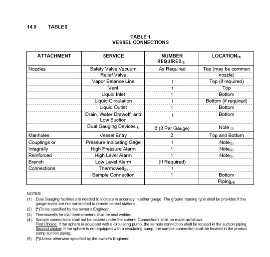
- (*)Unless specified by the Owner’s Engineer, connections to a sphere shall be limited to those listed in Table 1.
- (*)A manhole shall be provided in the top and bottom of each sphere. The minimum acceptable size shall be NPS 24. Larger sizes may be specified by the Owner’s Engineer to meet ventilation requirements for work inside large spheres.
- The hydrocarbon pump suction internal extension shall be 6 inches above the bottom tangent of the sphere or 6 inches above the water draw–off inlet, whichever is higher.
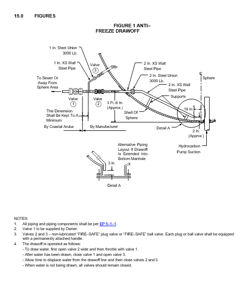
- If a water draw–off is specified for spheres that will operate in a freezing climate, it shall be in accordance with Figure 1. If it is possible for water to accumulate and freeze in a bottom manhole, the draw–off pipe shall be extended down to within 3 inches of the manhole cover. A union shall be provided at the turndown point above the manhole to facilitate access. If the sphere is to be used for storage of materials subject to polymerization or formation of peroxide (i.e., butadiene, isoprene, etc.), the internal water draw–off piping shall be omitted and the draw–off connection shall be flush with the bottom.
- (*)If a water draw–off is specified for spheres in a nonfreezing climatic location and the product will auto-refrigerate below 32°F on reduction to atmospheric pressure, the water draw–off may be located in the bottom of the sphere, bottom manhole cover plate, or on a bottom nozzle without an internal riser, whichever location provides for complete water removal. The water draw–off shall be at least 3/4 inch, but shall not exceed 2 inches, and shall be equipped with two valves at least 6 inches apart. The valve nearest the vessel shall be of a quick–closing type, such as a non-lubricated “Fire–Safe” plug valve or “Fire–Safe” ball valve. Each plug or ball valve shall be equipped with a permanently attached handle.
- Sphere support legs shall be provided with NPT ¼-inch vent holes. These holes shall be plugged with plastic sealant after the sphere has been hydrostatically tested.
- Sphere support legs are to be fireproofed in accordance with EP 11–2–1.
- Spheres shall be insulated in accordance with EP 11–3–4.
- Firewater spray systems for pressure storage spheres shall be per EP 3–5–3.
FABRICATION
- Fabrication of pressure storage spheres shall be in accordance with EP 7–1–1 and the additional requirements of this Practice.
- Vessels that cannot be completely shop fabricated shall be designed to minimize the amount of field welding and post weld heat treated (PWHT) that is required. Fittings such as branches and column support connections to the shell shall be welded to the sphere plates in the shop and PWHT, prior to delivery on site.
INSPECTION AND TESTING
- Inspection and testing shall be in accordance with EP 7–1–1 and the additional requirements of this Practice.
- All pressure containing butt welds for sphere construction shall be 100% radiographed.
- Weld inspection shall be performed in the shop to the maximum extent possible for vessels that cannot be completely shop fabricated.
- The root pass of the support leg to shell weld shall be examined by the magnetic particle method. After completion of the PWHT and before shipment from the Manufacturer’s shop, all attachment welds shall be inspected by the wet fluorescent magnetic particle technique. For this purpose the welds shall be ground sufficiently to remove surface irregularities which could mask indications of defects.
10.0 REJECTION AND REPAIR
Procedures for rejection and repair shall be in accordance with EP 7–1–1.
11.0 HYDROTEST REQUIREMENTS AND NOZZLE PAD TESTING
Hydrotest requirements and nozzle pad testing shall be in accordance with EP 7–1–1.
12.0 PAINTING, MARKING, PACKAGING AND SHIPPING
Painting, marking, packaging and shipping requirements shall be in accordance with EP 7–1–1.
13.0 ERECTION PLANS AND DRAWINGS
Requirements for erection plans and drawings shall be in accordance with EP 7–1–1.
© 2026 Inflection Point Engineering, LLC. All rights reserved. The content of this page — including calculation methods, reference data, written analysis, interactive tools, and source code — is the intellectual property of Inflection Point Engineering, LLC and is protected under applicable copyright, trademark, and trade secret laws. Unauthorized reproduction, redistribution, modification, or derivative use in whole or in part is prohibited without prior written consent.
Disclaimer. This material is provided for informational and educational purposes only and does not constitute professional engineering advice. Calculations, reference data, and methodologies are based on published standards and accepted engineering practice but are not a substitute for engineering judgment, site-specific analysis, or review by a licensed Professional Engineer. Inflection Point Engineering, LLC makes no warranties, express or implied, regarding the accuracy, completeness, or fitness for a particular purpose of any content presented here, and shall not be liable for any direct, indirect, incidental, or consequential damages arising from its use. Users assume all risk associated with applying this content to real-world design, operations, or decisions.
© 2026 Inflection Point Engineering, LLC. All rights reserved.