 Section 9 — Storage Tanks
Supplemental Requirements for Atmospheric
IPE Engineering Practice IPE-EP-9-3-1
Document number: IPE-EP-9-3-1 · Section: 9 — Storage Tanks

SCOPE
- This Practice covers supplemental requirements related to documentation, data, quality control, inspection, marking, packaging and shipping for atmospheric storage tanks designed in accordance with per API 65O and low pressure storage tanks designed in accordance with API 62O.
- Design, fabrication, inspection and testing of atmospheric storage tanks and low pressure storage are covered in EP 9-1-1, and EP 9-2-1, respectively.
- Any deviation from this Practice must be approved by the procedure described in EP 1-1-3.
- An asterisk (*) indicates that a decision by the Owner or Owner's Engineer is required, or that additional information is furnished by the Purchaser.
- A revision bar indicates all changes made to this Revision.
2.0 REFERENCES
The latest edition of the following standards and publications are referred to herein.
STANDARDS AND PUBLICATIONS
| IPE Engineering Practices |
|---|
| EP 1-1-3 Deviations to IPE Engineering Practices EP 4-2-7 Foundations for Atmospheric Storage Tanks EP 9-1-1 Atmospheric Storage Tanks EP 9-1-1 DS Atmospheric Storage Tanks Data Sheet EP 9-1-1 C Atmospheric Storage Tanks Inspection Checklist EP 9-2-1 Low Pressure Storage Tanks EP 9-2-1 DS Low Pressure Storage Tanks Data Sheet EP 9-2-1 C Low Pressure Storage Tanks Inspection Checklist EP 14-1-5 Export Protection and Packaging of Equipment EP 15-1-4 Positive Materials Identification (PMI) |
| API Publications |
| Std 62O Design and Construction of Large, Welded, Low-Pressure Storage Tanks Std 65O Welded Steel Tanks for Oil Storage |
DEFINITIONS
- Certificates of Compliance - A document by which the material manufacturer (or seller to the extent that the Code allows) certifies that the material represented has been produced and tested in accordance with the requirements of the basic Material Specification shown on the certificate. Objective evidence of compliance with the requirements of the Material Specification shall be maintained in the records of the material manufacturer. However, certificates of compliance shall include reports or results of tests required by the Material Specification or the Purchase Order.
- Certified Material Test Report (CMTR) - A document, or documents, on which are recorded the results of tests, examinations, repairs, or treatments required by the Material Specification. Supplementary or special requirements required by the Purchase Order in addition to the requirements of the Material Specification shall also be included on the CMTR. The specification of the material being represented including the year of issue and the material heat number shall also be included on the CMTR. All such documents shall identify the applicable Material Specification and shall be identified to the material represented.
- Inspector - A Inflection Point Engineering, LLCappointed engineer or inspector.
- Manufacturer - The recipient of a direct or indirect purchase order for materials and/or equipment. In this context, a direct order is one issued to a manufacturer by a contractor or the Owner. An indirect order is one issued to a manufacturer by a vendor (recipient of a direct order) for materials, fabricated components, or subassemblies.
- Owner - IPE Refining Company.
- Owner's Engineer - A Inflection Point Engineering, LLCappointed engineer.
- Purchase Order - The contractual document given to the Manufacturer to authorize a purchase.
- Purchaser - The party placing a direct purchase order. The purchaser is the Owner's designated representative.
- Quality Control Plan - The Manufacturer's job specific documented plan for ensuring that all specified technical requirements will be followed. The Quality Control Plan shall include, as a minimum, the following; fabrication schedule including all heat treatment requirements, forming and rolling procedures, and an inspection and test plan with a schedule identifying all inspection points required by the Owner.
- Quality Control System - The Manufacturer's documented system for ensuring that all applicable code requirements for the manufacturing process including material handling and identification, design, fabrication, inspection and testing are followed.
DATA FURNISHED BY PURCHASER
- The Purchaser shall provide the following information:
- Procurement documents
- Completed Tank Data Sheet per EP 9-1-1 DS or EP 9-2-1 DS, as applicable, and line drawing.
- Applicable IPE Engineering Practices with approved addenda.
- Inspection Checklist per EP 9-1-1C or EP 9-2-1C, as applicable.
- (*)As a minimum, a schedule for receipt of the following information and the required number of copies will be specified by the Purchaser:
- Completed tank data sheet per EP 9-1-1 DS or EP 9-2-1 DS as applicable.
- Subcontractor names and addresses
- Dimensional outline drawing - plan & elevation
- Foundation loading diagram
- Tank Accessories
- Tank Design Report per paragraph 6.2
- Welding procedure specifications and procedure qualification records, weld maps, welder or welding operator qualification tests
- Quality Control Plan including; fabrication sequence including all heat treatment requirements, forming and rolling procedure, and an inspection and test plan with schedule identifying all inspection points required by the Owner.
- Quality control system 1O) NDE procedures
- Personnel qualification certificates for NDE
- Required Code reports for NDE
- Certified Material Test Reports or Certificates of Compliance
- Recommended spare parts list
- Tank Record Book per paragraph 6.3
- Detailed fabrication drawings including:
- Drawing list
- General tank details including shell, nozzles, manways, annular plate and bottom designs
- Details for fixed, internal or external floating roofs, as applicable
- Details for top and intermediate wind girders
- Details for all tank internals
- Anchor bolt template, if applicable
- Ladder and platform details
- Erection drawings
MANUFACTURER'S RESPONSIBILITY
General
- The Manufacturer shall assume responsibility for designing and fabricating the tank in accordance with the specified design conditions.
- The Manufacturer shall provide the information described in paragraph 4.2. The number of copies and schedule shall conform to the Purchaser's requirements.
Conflicting Requirements
The Manufacturer shall refer all conflicting requirements contained in the Purchase Order to the Purchaser in writing for clarification and resolution before proceeding with the manufacture or procurement of the affected part(s). The Manufacturer is not at liberty to assume which requirements govern.
Quality Control
- (*)The Manufacturer shall operate a Quality Control System to ensure that the technical requirements of APl 65O or APl 62O, as applicable, are achieved. The Owner's Engineer may require demonstration of the Quality Control System, but this may be waived if the system has been verified recently by an accreditation scheme acceptable to the Owner's Engineer.
- (*)The Manufacturer shall submit a Quality Control Plan that shall be reviewed and approved by the Inspector.
- (*)Unless otherwise specified by the Owner's Engineer, a copy of the quality control plan signed by all inspection parties shall be submitted to the Owner's Engineer for approval prior to the start of fabrication.
- The Manufacturer shall ensure that technical and quality assurance requirements specified in the Purchase Order are applied to all materials, equipment and services provided by subcontractors and to any free-issue materials.
Marking
- All materials shall be identified by stamping with "low stress" steel stamps having round or "U" shaped cross sections, with "interrupted-dot" die stamps, marking paint, or water insoluble ink.
- Marking paint or water insoluble ink used on austenitic and high nickel alloy steels shall contain no substance (e.g., metallic pigments, sulfur or chlorides) which would be harmful to these materials at ambient or elevated temperatures. The Manufacturer shall submit analysis of marking material to the Purchaser. The submittal shall demonstrate (by chemical analysis and history of use) that the material meets these requirements.
- Internals, clips, lugs, or other similar attachments that are removable and are to be assembled by others shall be marked with piece numbers or identification in assembly and match-marked.
- For tanks, nozzle insert plates, or other components that have been post weld heat treated (PWHT), the following sign shall be painted on the tank or plate after heat treatment. The sign shall be in letters approximately 4 inches high painted with white paint.
- On vertical tanks, this sign shall be located on two opposite sides near the bottom tangent line and repeated at approximately each ten (1O) feet of height, but rotated 9O degrees.
- On horizontal tanks, the sign shall be located on both sides near the horizontal centerline.
"POST WELD HEAT TREATED... NO WELDING OR BURNING PERMITTED ON THIS TANK"
- The Purchase Order number and the Tank identification number shall be painted with white paint on the side of the tank above the manway(s).
- All temporary support components required for maintaining roundness or shipping shall be painted yellow and marked with the following statement:
"SHIPPING/FABRICATION DEVICE . . . REMOVE BEFORE UNIT STARTUP"
Packaging and Shipping
- Shop fabricated tanks shall be thoroughly clean and free of loose scale, dirt and foreign material. Liquid used for testing or cleaning shall be completely drained. All tank openings shall be blanked. Stainless steel tanks shall be blown dry with air, and all nozzle, manhole, vent and connection openings shall be blanked, plugged or capped to prevent the entry of moisture.
- The Manufacturer shall be responsible for suitably packaging each shop fabricated tank or component and adequately supporting and securing all tank nozzles, manways and internals to protect them from damage or loss during handling and shipment in accordance with the Purchase Order and the following requirements:
- All material and methods of packing shall conform to the specifications referenced in the Purchase Order.
- Packages shall include lifting lugs or designated lifting points.
- Each shop fabricated tank, crate, or bag shall be durably marked with the receiving address, Purchaser's Item Number, and the complete Purchase Order Number. As a minimum, all markings shall be in the English language.
- The Manufacturer shall include a packing list in each shipment, listing the contents of each box, crate, bag, and skid by assembly piece mark, individual piece mark, or by tank number. The list shall state whether the contents constitute complete or partial shipment.
- (*)Shop fabricated tanks shall not be transported to the jobsite as above-deck cargo without prior written approval of the Purchaser.
- (*)Where clearances for shipping require alteration or cutting off of shop fabricated tank nozzles, clips, lugs, or other similar attachments, the Manufacturer shall submit loading diagrams showing the attachments that require reorientation or removal. No changes shall be made unless the Purchaser has obtained written approval.
- Small parts of the tanks shall be shipped bagged, boxed, or otherwise protected from damage or loss. Spare gaskets shall be tagged with the equipment item number and location. Gaskets shall be boxed separately and shipped with the tank.
- The Manufacturer shall provide any special protection or packaging, and details of any storage, shelf life, or maintenance instructions which are not within the scope of the Purchase Order but which pertain to the Manufacturer's guarantee or are otherwise necessary for protection of the tank.
- Protection for flange faces, threaded connections, weld bevels, etc., shall be as follows:
- (*)All machined and threaded surfaces of carbon steel and ferritic alloy steel materials, except weld bevels, shall be coated with a rust preventive approved by the Purchaser.
- (*)Weld bevels shall be free of dirt, oil, grease, scale, rust, and other foreign materials. All weld bevels of carbon steel and ferritic alloy steel materials shall be coated, after cleaning, on the inside and outside for a distance of approximately 3 inches from the end of the weld bevel with a weldable rust preventive approved by the Purchaser.
- All piping or nozzle weld bevels shall be closed with metal or plastic caps to prevent damage and entrance of foreign materials.
- All socket-weld ends and plain ends shall be closed with metal or plastic protectors that fit either inside or outside to prevent damage and entrance of foreign materials.
- Threaded openings shall be plugged with round headed threaded plugs of the same material as the connected part and sealed with tetrafluoroethylene tape thread sealant.
- Flanged openings shall be protected and made waterproof with plastic flange covers or full size No. 1O gage minimum thickness steel covers and 1/8-inch thick rubber gaskets between the flange and cover. When steel flange covers are furnished, they shall be secured with appropriately sized machine bolts as follows: For flanges having 4 to 28 bolt holes, a bolt shall be placed in at least every other hole, with a minimum of 4 bolts. For flanges having more than 28 bolt holes, bolts shall be placed in at least every fourth bolt hole.
- Austenitic stainless steels used in tanks shall not be exposed to wetting by salt water or salt spray. Protective coatings used to prevent such exposure are required and shall be approved by the Purchaser.
- Additional requirements for export packaging are covered in EP 14-1-5.
- For shop fabricated tanks, tell tale holes in reinforcing pads shall be left unplugged and filled with grease after the hydrostatic test and prior to shipment
Spare Parts
- Two (2) sets of spare gaskets shall be furnished for all girth and manway flanges.
- An additional 1O% (rounded to the next higher whole number)of stud bolts for all girth and manway flanges shall be furnished.
DOCUMENTATION
Final Fabrication Drawings
- The final or "as-built" fabrication drawings shall include, but shall not be limited to, the following:
- All information on the applicable tank data sheet, see EP 9-1-1 DS or EP 9-2-1 DS
- Dimensions of all tank components including internals
- Gasket and flange details including flange face finishes
- Nozzle details
- Internal construction details including all shell attachments and location
- Full scale drawing of the tank nameplate
- Support and other appurtenance details
- Foundation details
- Anchor bolt orientation and size, if applicable
- All weld joint details in cross section, weld map, and applicable welding procedures
- Heat treatment requirements
- Weld hardness requirements
- Non-destructive testing requirements
- Fabrication drawings with proprietary clauses are unacceptable.
- (*)After the Owner's Engineer approval and final revision, approved fabrication drawings shall be furnished to the Owner's Engineer. The Purchaser will specify the number of copies of approved fabrication drawings.
(*)If modifications to the approved fabrication drawings are required during fabrication, one reproducible and four copies of "as-built" drawings (only those affected) shall be issued to the Owner's Engineer. Modification shall not be made to the approved design without receiving approval from the Owner's Engineer and the Inspector
.
Tank Design Report
- A Tank Design Report shall be provided for each tank This Report shall include the following:
- All mechanical design calculations shall be provided for the following tank components to demonstrate compliance with the relevant code. For components falling beyond the scope of the applicable tank standard, the Manufacturer shall be responsible for providing adequate calculations to justify the design. The Manufacturer shall use the English System of Units (stress and pressure shall be expressed as lb/in2 , length as inches, and force as lbs.) on all drawings and calculations. The design calculations shall include the following:
- Shell design (liquid head, wind, seismic, etc.)
- Nozzle reinforcement for non-standard APl nozzle designs
- Wind stiffeners, primary and intermediate
- Wind overturning stability and anchor bolt design including anchor lugs/chairs
- Fixed roof design including rafters, girders, roof plates and frangible joint design
- Internal and external floating roof design including all components
- Foundation settlement prediction and design
- Overflow sizing
- Vent sizing
- Completed data sheets for atmospheric or low pressure storage tanks, see EP 9-1-1 or EP 9- 2-1, respectively, corrected to reflect the as-built conditions.
- Tank design calculations made with the use of computer programs must either be accompanied by the appropriate program documentation or substantiated by detailed hand calculations.
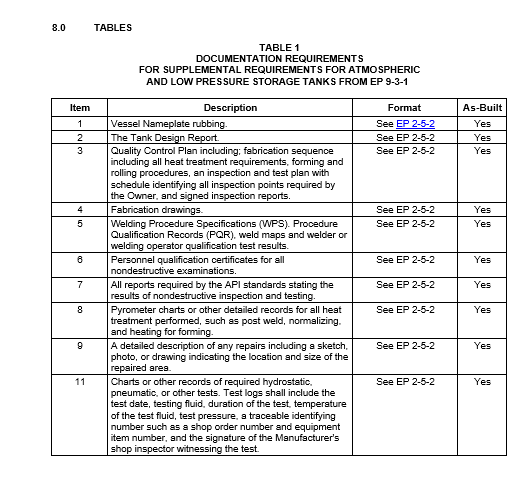
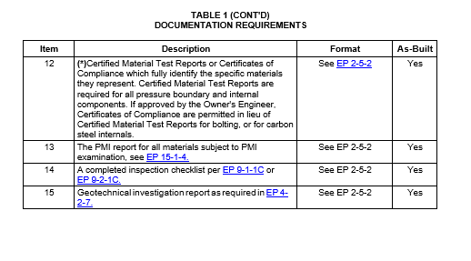
Tank Record Book
- On completion of construction of each tank, the Manufacturer shall assemble and deliver with the tank, two copies of a Tank Record Book which as a minimum, shall contain the items in Table 1.
- Unless otherwise specified in the Purchase Order, the Manufacturer shall retain the Tank Record Book for five (5) years.
7.0 INSPECTION AND REJECTION BY PURCHASER
All tank fabrication is subject to inspection and rejection by the Owner in accordance with the requirements of the Purchaser and EP 9-1-1 or EP 9-2-1, as applicable.
© 2026 Inflection Point Engineering, LLC. All rights reserved. The content of this page — including calculation methods, reference data, written analysis, interactive tools, and source code — is the intellectual property of Inflection Point Engineering, LLC and is protected under applicable copyright, trademark, and trade secret laws. Unauthorized reproduction, redistribution, modification, or derivative use in whole or in part is prohibited without prior written consent.
Disclaimer. This material is provided for informational and educational purposes only and does not constitute professional engineering advice. Calculations, reference data, and methodologies are based on published standards and accepted engineering practice but are not a substitute for engineering judgment, site-specific analysis, or review by a licensed Professional Engineer. Inflection Point Engineering, LLC makes no warranties, express or implied, regarding the accuracy, completeness, or fitness for a particular purpose of any content presented here, and shall not be liable for any direct, indirect, incidental, or consequential damages arising from its use. Users assume all risk associated with applying this content to real-world design, operations, or decisions.
© 2026 Inflection Point Engineering, LLC. All rights reserved.