 Section 9 — Storage Tanks
Low Pressure Storage Tanks
IPE Engineering Practice IPE-EP-9-2-1
Document number: IPE-EP-9-2-1 · Section: 9 — Storage Tanks
SCOPE
- This Practice covers requirements governing the design, fabrication, inspection and testing of low pressure storage tanks constructed to API 620.
- Tanks designed, fabricated, inspected and tested to this Practice have attributes similar to pressure vessels or flat bottom storage tanks, depending on the application. Therefore, the general requirements of EP 7-1-1 and EP 9-1-1, as applicable, form the basis of this Practice.
- Any deviation to this Practice must be approved by the procedure described in EP 1-1-3.
- An asterisk (*) indicates that a decision by the Owner's Engineer or Owner is required, or that additional information is furnished by the Purchaser.
- A revision bar indicates all changes made to this Revision.
2.0 REFERENCES
The latest edition of the following standards and publications are referred to herein.
STANDARDS AND PUBLICATIONS
STANDARDS AND PUBLICATIONS (CONT.)
| API Publications |
|---|
| Std 5L Specification Standard for Line Pipe Std 620 Design and Construction of Large, Welded, Low-Pressure Storage Tanks Std 2508 Design and Construction of Ethane and Ethylene Installations Std 2510 Design and Construction of Liquefied Petroleum Gas (LPG) Installations Publ 941 Steels for Hydrogen Service at Elevated Temperatures and Pressures in Petroleum Refineries and Petrochemical Plants |
| ASTM Standards |
| A27 Steel Castings, Carbon, for General Application A36 Structural Steel A105 Forgings, Carbon Steel, for Piping Components A106 Seamless Carbon Steel Pipe for High-Temperature Service A131 Structural Steel for Ships A181 Forgings, Carbon Steel, for General-Purpose Piping A333 Seamless and Welded Steel Pipe for Low-Temperature Service A350 Forgings, Carbon and Low-Alloy Steel, Requiring Notch Toughness Testing for Piping Components A442 Pressure Vessel Plates, Carbon Steel, Improved Transition Properties A516 Pressure Vessel Plates, Carbon Steel, for Moderate- and Lower-Temperature Service A524 Seamless Carbon Steel Pipe for Atmospheric and Lower Temperatures A537 Pressure Vessel Plates, Heat Treated, Carbon Manganese-Silicon Steel A573 Structural Carbon Steel Plates of Improved Toughness A662 Pressure Vessel Plates, Carbon-Manganese, for Moderate and Lower Temperature Service A671 Electric-Fusion-Welded Steel Pipe for Atmospheric and Lower Temperatures A737 Pressure Vessel Plates, High-Strength, Low Alloy Steel |
DEFINITIONS
- Contractor - Company or business that agrees to furnish materials or perform specified services at a specified price and/or rate to the Owner.
- Hydrogen Rich Service - A service defined as a combination of hydrogen partial pressure and temperature at or below the curve for carbon steel per Figure 1 of API Publication 941, latest edition, and with a hydrogen partial pressure greater than 100 psia.
- Hydrogen Service - A service defined as a combination of hydrogen partial pressure and temperature above the curve for carbon steel per Figure 1 of API Publication 941, latest edition.
- Inspector - A IPE Refining Company appointed engineer or inspector.
- Manufacturer - The recipient of a direct or indirect purchase order for materials and/or equipment. In this context, a direct order is one issued to a manufacturer by a contractor or the Owner. An indirect order is one issued to a manufacturer by a vendor (recipient of a direct order) for materials, fabricated components, or subassemblies.
- Owner - Inflection Point Engineering, LLC
- Owner's Engineer - A Inflection Point Engineering, LLC appointed engineer.
- Purchase Order - The contractual document given to the Manufacturer to authorize a purchase.
- Purchaser - The party placing a direct purchase order. The purchaser is the Owner's designated representative.
DATA SHEET, DOCUMENTATION, AND PURCHASING REQUIREMENTS
- (*)The Owner's Engineer shall complete the Low Pressure Storage Tank Data Sheet, EP 9-2- 1DS, along with a tank drawing showing all design data, dimensions, schedule of openings, notes, and all other requirements necessary to prepare the design and detailed fabrication and erection drawings. The Manufacturer shall use this information to supply with his quotation a completed tank data sheet containing all the relevant information necessary for appraisal of the mechanical design by the Purchaser. Also included shall be any additional drawings, specifications, etc., and a list of any proposed subcontractors.
- Upon completion of tank fabrication, the Manufacturer shall furnish the Owner's Engineer with a copy of the Low Pressure Storage Tank Data Sheet corrected to reflect as-built conditions.
- (*)Supplemental requirements for low pressure storage tanks purchased to this Practice are covered in EP 9-3-1.
5.0 QUALITY ASSURANCE
The Manufacturer shall have as part of his usual business practice an established quality control system. In addition, a quality control plan shall be developed for the manufacture of a new low pressure storage tank to ensure that all technical requirements are followed.
Requirements for this quality control plan are covered in EP 9-3-1.
MATERIALS
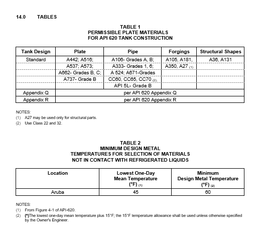
- (*)Unless otherwise specified by the Owner's Engineer, permissible materials of construction for tank components shall be in accordance with Table 1. Final materials of construction shall be approved in writing by the Owner prior to purchasing of materials.
- Selection of materials of construction for materials in contact with non refrigerated liquids shall be based on paragraph 2.2 of API 620. The design metal temperature shall be based on the information in Table 2.
- Selection of materials of construction for material in contact with refrigerated liquids shall be based on the applicable requirements of Appendix Q and R of API 620.
- When the design utilizes normalized plate, the fabricator shall not destroy the normalized properties of the plate during fabrication.
- Materials for gaskets and bolting shall be in accordance with EP 5-2-2. Spiral wound gaskets shall be used with all nozzle connections and sheet gaskets shall be used with manhole connections.
- (*)Additional requirements for materials, welding control, Brinell hardness and heat treatment will be specified by the Owner's Engineer for tanks containing caustic, hydrogen sulfide, cyanide and amine, see EP 10-2-1 and EP 10-2-3.
- Cast fittings or other components shall not be used in the shell or bottom.
- Annular plates for flat bottom storage tanks shall be of the same material specification and grade as the bottom shell course.
- Materials for permanent structural attachments welded to the shell shall be of the same nominal composition as the tank shell materials.
DESIGN
- The design of low pressure storage tanks shall be in accordance with API 620 and the additional requirements of this Practice.
- Design loads and load case combinations used to establish tank wall thicknesses shall be in accordance with EP 7-1-1.
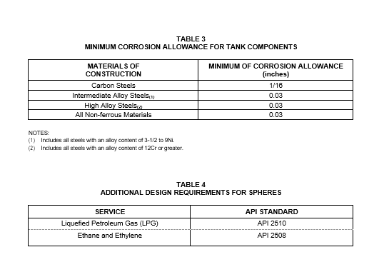
- (*)The minimum corrosion allowance for tank components shall be per Table 3. Hold-down straps, if required, shall be supplied with a 1/8 inch minimum corrosion allowance.
- (*)The design of nozzles and manways shall be in accordance with API 620 and the additional requirements stipulated in EP 7-1-1. The following will be specified by the Owner's Engineer:
- The number of manways and their locations.
- The number, type, size, and location of all instrument connections.
- The nozzle flange rating, size, elevation, orientation and location.
- The design of bottoms for flat bottom cylindrical storage tanks shall meet the requirements of EP 9-1-1. The thickness of bottom plates shall be a minimum of 1/4 inch plus the specified corrosion allowance, see paragraph 7.3.
- Tank foundation details shall be submitted for review to the Owner's Engineer. Final written approval by the owner is required before initiation of foundation construction.
- The design of auxiliary structures for operation and maintenance such as platforms, walkways and stairways shall be in accordance with EP 4-5-3 and the following:
- Stairways and platforms shall be provided to allow access to operating valves. The use of permanent ladders to service instruments, connections, and access will be specified.
- A stairway with handrail shall be provided from grade to the top of the tank.
- Guard railings and toe plates shall enclose all product nozzle, pressure relief device, and instrumentation attachments located at the top of the tank.
- (*)Pressure and vacuum relief devices, their associated block valves and piping shall be furnished and installed by Tank Manufacturer or Purchaser, as specified. The Manufacturer's proposal shall be submitted to Purchaser for review by the Owner's Engineer.
- (*)The tank Manufacturer shall furnish and install the firewater deluge and spray systems. These systems shall be designed in accordance with EP 3-5-3 and are subject to the approval of the Owner's Engineer.
- External tank support components are to be fireproofed in accordance with EP 11-2-1. In addition, fireproofing of supports for spheres, foundations for tanks, and pipe supports within dikes of tankage in refrigerated service shall also be designed to withstand thermal shock encountered in a spill when the liquid stored has an atmospheric boiling point below -50°F. If fireproofing is included as part of the tank Manufacturer's responsibility, such designs shall be submitted to purchaser for approval by the Owner's Engineer.
- Tanks shall be insulated in accordance with EP 11-3-4.
- Double wall tanks using loose fill insulation systems shall incorporate the following design features and criteria:
- Means to prevent alternate settling and compaction of the loose fill due to thermal and hydrostatic displacements of the inner and outer tank shells.
- The external design pressure for the inner tank shall be based on the static loads and stiffness properties of the insulation system, the purge gas pressure, and the internal partial vacuum design limit.
- Means to minimize the obstruction to flow of loose fill from the roof area to the wall. Locating the inner shell top compression rings on the interior of the inner tank is an acceptable design.
- (*)The number and location of fill nozzles for making-up insulation losses after cool-down are subject to approval by the Owner's Engineer.
- (*)Design of the insulating support system between the inner and outer tank bottoms for a double wall cylindrical tank shall be submitted to the Owner's Engineer for approval.
- In addition to the requirements of this Practice, low pressure storage tanks to be used in the services indicated in Table 4 shall also incorporate the design requirements stipulated in the associated API Standard.
FABRICATION AND ERECTION
- General
- Fabrication of low pressure storage tanks shall be in accordance with API 620 and the additional requirements of this Practice.
- Tanks that cannot be completely shop fabricated shall be designed to minimize the amount of field welding and post weld heat treatment (PWHT) that is required. Fittings such as branches and column support connections to the shell shall be welded in the shop and post-weld treated, prior to delivery on site. After completion of the PWHT and before shipment from the Manufacturer's shop, all attachment welds shall be examined by the wet fluorescent magnetic particle technique. For this purpose the welds shall be ground sufficiently to remove surface irregularities which could mask indications of defects.
- (*)If any shell opening must be cut in the tank shell for construction access, the fabrication installer shall cut it out and replace it. The shape of the opening, method of repair, and inspection are subject to the approval of the Owner's Engineer.
- All repairs and inspection due to defective welding shall be at the Contractor's expense.
- Welding
- Welding procedures for fabrication of low pressure storage tanks shall be in accordance with EP 7-1-5. Welding procedures for bottoms of flat bottom cylindrical storage tanks shall be per EP
9-1-2.
- (*)Fabrication involving welding shall not be subcontracted to others without advance written approval of the Owner's Engineer.
- All shell joints and shell connections shall be full penetration double welded butt joints that are background to sound metal and inspected prior to welding of the second side.
- For flat bottom tanks, the following fabrication details shall be used.
- (*)The shell to annular plate shall be a full penetration weld unless one of the following alternates is approved by the Owner's Engineer:
- A combination weld with a partial penetration groove and a fillet weld reinforcement.
- A double fillet weld with each fillet being a minimum of 2 layers.
- Annular plates shall be butt-welded with complete penetration and complete fusion.
- All bottom plates shall be two pass fillet welded to develop a minimum joint efficiency of 70%, see EP 9-1-1 and EP 9-1-2.
- Horizontal shell joints in plate 1/4 inch thick or less may be double submerged arc welded without backgouging provided all intermediate stops are ground out.
- The fit-up of plates shall be made using spacer shims and suitable erection clips. When the use of tack welds is unavoidable, these tack welds shall be removed before finish welding. The use of an excessive number of clips shall be avoided. Clips shall not be used to force poorly fabricated or deformed plates into position. They are intended only to lock the pieces or subassemblies together for welding.
- Temporary attachment welds at all locations on the pressure shell shall be removed by grinding. The surface shall be ground smooth to eliminate surface stress concentrations. If the resulting thickness in the ground area is less than the original design base metal thickness, the area shall be weld repaired and ground-smooth. All ground or weld repaired surfaces shall be magnetic particle or liquid penetrant examined before the final hydrotest.
- Attachment welds for tank anchors, shell stiffeners, insulation supports, stairway clips, pipe supports and similar components shall be continuously fillet welded, except that the fillet welds on the underside of shell stiffeners may be welded intermittently.
- Radial butt welds between shell stiffener sections shall terminate approximately 1/2 inch from the tank shell.
- Production weld test plates as specified in API 620 are required in addition to weld procedure qualification test plates. The production weld test plates shall be made from the applicable plates as supplied having the lowest Charpy Vee-notch minimum average energy for each welding procedure qualification. Also, production weld test plates shall be made in a similar manner for each change in one or more of the following parameters:
- Specified Charpy Vee-notch minimum average energy.
- Material specification.
- Final heat treated condition.
- Steel mill supplier.
- Electrode or wire nominal chemistry, or a change of manufacturer or electrode/flux combination.
- All welding to the tank shell shall be done prior to the final hydrostatic test.
- Qualification of welding procedures and welders on aluminum shall be done at the job site under actual production conditions.
- Heat Treatment
- Heat treatment requirements of tanks constructed to this Practice shall be in accordance with API 620 and EP 7-1-1.
- (*)Procedures for stress relieving shop or field fabricated tanks are subject to the approval of the Owner's Engineer.
- Field Erection
- Unless otherwise specified by the Owner's Engineer, when a difference in thickness exists between shell sections or shells and heads, the inside surface shall be aligned.
- The maximum allowable gap between nozzle reinforcing pads and the curvature of the shell to which they are attached shall not exceed 1/8 inch.
- Slip-on flanges, if used on nozzles, shall be positioned so that the distance from the face of the flange to the nozzle end shall be equal to the nozzle thickness plus approximately 1/8 inch.
Slip-on flanges shall be welded both inside and out with a minimum of two weld passes.
- For flat bottom storage tanks, the tank shell erection shall meet the following tolerance limits:
- Target tolerance for peaking is 1/4 inch. An occasional peaking up to 1/2 inch shall not be cause for rejection.
- Target tolerance for banding is 1/4 inch. An occasional banding up to 1/2 inch shall not be cause for rejection.
- Nameplate
- All vessels shall be furnished with a stainless steel nameplate. Required markings shall not be stamped directly on the vessel. Nameplates shall be installed on the Manufacturer's standard nameplate holder of sufficient length to project at least 1 inch beyond the vessel insulation. The letters and figures shall be at least 5/32 inch high. A drawing of the nameplate shall be included in the Manufacturer's vessel drawings.
- The nameplate layout and required information shall be in accordance with API 620.
- The nameplates of vertical vessels shall be located on the shell above the lowest manhole. On horizontal vessels, they shall be located in the center of a head or above a manhole in a head. The nameplate location shall be shown on the manufacturer's drawings.
INSPECTION AND TESTING
- General
- (*)Inspection and testing shall be in accordance with API 620 and the requirements of this Practice. In case of conflict between the requirements of these documents, the most stringent requirements, as determined by the Owner's Engineer, shall govern.
- Shop drawings of the tank and all data reports shall be available to the Inspector at the time of the inspection. Surfaces shall not be painted nor the tank shipped until the Owner's inspection is complete. In addition to any required inspection per API 620, materials, all fabrication, and methods of shipping shall be subject to inspection by the Inspector. Rejections by him are final. The inspection does not relieve the Manufacturer of his responsibility for complying with this Practice.
- Positive Material Identification (PMI) shall be in accordance with EP 15-1-4.
- The responsibility for examination rests with the vessel Manufacturer. However, the Inspector shall at all times have access to the shop of any Manufacturer engaged in supplying material or in fabricating the tank for the purpose of inspecting and, if necessary, rejecting such material and work which does not meet with the requirements of this Practice.
- Manholes, nozzles, and flush-type cleanout fittings shop welded into a tank plate, insert plate or reinforcing pad for field installation, shall be inspected by the Inspector at the tank fabricator's shop.
- When field erection is required, the qualifications of field inspection personnel engaged by the tank erector shall be submitted to the purchaser for Owner's Engineer approval.
- Radiographic Examination
- Radiographic examination shall be in accordance with API 620 and the additional requirements of this Practice.
- Extent of radiographic examination shall be determined by the following:
- For vertical cylindrical flat bottom tanks; inspection shall be per EP 9-1-1.
- For non-vertical tanks with a shell thickness equal to or greater than 1-1/2 inches; 100% radiography of all shell butt joints is required.
- For non-vertical tanks with a shell thickness less than 1-1/2 inches, spot radiography is required. One spot shall be taken for every 20 feet of weld seam in both the vertical and horizontal directions. One spot shall be taken for each welder and welding procedure used on the tank. At least 25% of the radiographs taken shall be at horizontal to vertical junctions.
- The vertical (meridional) seams of cylindrical tanks, and all seams of non-cylindrical tanks, constructed to Appendix Q or R of API 620 shall be 100% radiographed.
- Radiograph film length shall be 10 inches minimum, except if the weld is less than 10 inches long. In such cases, film length shall be full length of weld.
- When spot radiographs are taken at horizontal to vertical joint intersections, the minimum radiograph film length shall be 10 inches in both the horizontal and vertical directions.
- (*)Unless otherwise specified by the Owner's Engineer, radiography for final acceptance shall be performed after the final PWHT.
- If in the opinion of the Inspector, the radiographs show unacceptable defects, the defective welding shall be repaired in accordance with Section 10.0 prior to shipment of the vessel.
- All welds, including weld repairs, placed in any part (regardless of the material, thickness, or service) before the part is subjected to severe working (ratio of thickness to local radius greater than 5 percent) by any means (including spinning, pressing, and rolling) shall be given a complete radiographic and either magnetic particle or liquid penetrant examination after the completion of the severe working and before further fabrication is performed.
- Manual "stringer bead" or irregular surface welds shall be flat-topped prior to radiography to remove surface ripples that may obscure internal indications.
- Radiographs disclosing defects shall be followed by tracer radiographs until the extent of the defect is determined, or the entire weld seam shall be removed and rewelded. All tracer radiographs and subsequent weld repair shall be at the Contractor's expense.
- All repair films and the corresponding original films of defective welds shall be retained for review by the Inspector.
- Ultrasonic Examination
Requirements for ultrasonic examination shall be in accordance with EP 7-1-1.
- Magnetic Particle and Liquid Penetrant Examination
- For vertical cylindrical flat bottom tanks, magnetic particle and liquid penetrant inspection shall be in accordance with EP 9-1-1.
- For all other tanks, requirements for magnetic particle and liquid penetrant examination shall be in accordance with EP 7-1-1.
- Vacuum Box Testing
- For vertical cylindrical flat bottom tanks vacuum box testing shall be per EP 9-1-1.
- (*)Requirements for vacuum box testing of all other tanks shall be specified by the Owner's Engineer.
10.0 REJECTION AND REPAIR
Procedures for Rejection and Repair shall be in accordance with EP 7-1-1.
HYDROTEST REQUIREMENTS AND NOZZLE PAD TESTING
- Hydrostatic testing of tanks constructed to this Practice shall be in accordance with API 620 and the additional requirements stipulated in EP 7-1-1.
- Nozzle pad testing requirements are stipulated in EP 7-1-1.
PAINTING, LINING AND COATINGS
- General requirements for painting are covered in EP 7-1-1.
- (*)Coating requirements for the tank shell and floor shall be in accordance with EP 10-3-7. Coating materials shall be specified by the Owner's Engineer based on service requirements.
SETTLEMENT MEASUREMENT BENCHMARK
- Requirements for shell and bottom settlement measurements for flat bottom cylindrical tanks are covered in EP 9-1-1.
- (*)Settlement measurements for tanks of other shapes will be specified by the Owner.
© 2026 Inflection Point Engineering, LLC. All rights reserved. The content of this page — including calculation methods, reference data, written analysis, interactive tools, and source code — is the intellectual property of Inflection Point Engineering, LLC and is protected under applicable copyright, trademark, and trade secret laws. Unauthorized reproduction, redistribution, modification, or derivative use in whole or in part is prohibited without prior written consent.
Disclaimer. This material is provided for informational and educational purposes only and does not constitute professional engineering advice. Calculations, reference data, and methodologies are based on published standards and accepted engineering practice but are not a substitute for engineering judgment, site-specific analysis, or review by a licensed Professional Engineer. Inflection Point Engineering, LLC makes no warranties, express or implied, regarding the accuracy, completeness, or fitness for a particular purpose of any content presented here, and shall not be liable for any direct, indirect, incidental, or consequential damages arising from its use. Users assume all risk associated with applying this content to real-world design, operations, or decisions.
© 2026 Inflection Point Engineering, LLC. All rights reserved.