 Section 9 — Storage Tanks
Tank Inspection, Repair, Alteration, Fitness for Service
IPE Engineering Practice IPE-EP-9-1-5
Document number: IPE-EP-9-1-5 · Section: 9 — Storage Tanks

SCOPE
- This Practice covers requirements for inspection, fitness-for-service evaluation, repair, alteration and reconstruction of atmospheric storage tanks. The basis for these requirements is contained in API 653 and API 579. This Practice also covers requirements for the evaluation of suitability for service of existing atmospheric storage tanks.
- The requirements in this Practice are supplemental to those stipulated in API 653. To facilitate use, the organization of this Practice has been arranged to correspond to that of API 653; the title and content of Sections 4 through 14 correspond to Sections 1 through 11 of API 653.
- Any deviation to the requirements of this Practice must be approved by the procedure described in EP 1-1-3.
- An asterisk (*) indicates that a decision by the Owner, Owner's Engineer or Inspector is required.
- A revision bar indicates all changes made to this Revision.
2.0 REFERENCES
The latest edition of the following standards and publications are referred to herein.
STANDARDS AND PUBLICATIONS
| IPE Engineering Practices |
|---|
| EP 1-1-3 Deviations to IPE Engineering Practices EP 4-1-1 Design Criteria and Loads for Structures EP 4-2-7 Foundations for Atmospheric Storage Tanks EP 4-2-10 Atmospheric Storage Tank Foundation Monitoring, Repair and Retrofit EP 5-7-1 Hot Taps EP 9-1-1 Atmospheric Storage Tanks EP 9-1-1C Atmospheric Storage Tanks Inspection Checklist EP 9-1-2 Welding Requirements for Atmospheric Storage Tanks EP 9-1-3 Tank Roof Seals EP 9-1-3C Tank Roof Seals Inspection Checklist EP 10-3-7 Internal Lining and Resin Repair |
| API Publications |
| 579 Recommended Practice for Fitness-For-Service 650 Welded Steel Tanks for Oil Storage 653 Tank Inspection, Repair, Alteration, and Reconstruction 2000 Venting Atmospheric and Low Pressure Storage Tanks (Nonrefrigerated and Refrigerated) 2015 Cleaning Petroleum Storage Tanks 2015A Guide for Controlling the Lead Hazard Associated with Tank Entry and Cleaning |
STANDARDS AND PUBLICATIONS (CONT.)
DEFINITIONS
- Aggressive Environmental Service (AES) - Process services which result in material degradation such as cracking, scaling, blistering, and severe pitting and/or corrosion. Examples of such services are hydrogen service, wet hydrogen sulfide, cyanides, caustic, amine, and hydrofluoric acid. AES process fluid are defined in EP 10-2-1.
- Contractor - Company or business that agrees to furnish materials or perform specified services at a specified price and/or rate to the Owner.
- Inspector - A Inflection Point Engineering, LLC appointed engineer or inspector.
- Purchase Order - The contractual document given to the Manufacturer to authorize a purchase.
- Manufacturer - The recipient of a direct or indirect purchase order for materials and/or equipment. In this context, a direct order is one issued to a manufacturer by a contractor or the Owner. An indirect order is one issued to a manufacturer by a vendor (recipient of a direct order) for materials, fabricated components, or subassemblies.
- Owner - Inflection Point Engineering, LLC.
- Owner's Engineer - A Inflection Point Engineering, LLC appointed engineer.
- Purchaser - The party placing a direct purchase order. The purchaser is the Owner's designated representative.
INTRODUCTION (API 653 SECTION 1)
- (*)The requirements of this Practice are supplemental to those stipulated in API 653. In the event of a conflict, the most stringent requirements, as determined by the Owner's Engineer, shall govern.
- (*)If any provision of this Practice presents a direct or implied conflict with any statutory regulation, the regulation should govern, and the Owner's Engineer shall document details of the conflict. However, if the requirements of this Practice are more stringent than the requirements of the regulation, as determined by the Owner's Engineer, then the requirements of this Practice shall govern.
- (*)Unless otherwise specified by the Owner's Engineer, the "applicable standard" as used in API 653 refers to EP 9-1-1.
SUITABILITY FOR SERVICE (API 653, SECTION 2)
- General
- An evaluation of the suitability for service of an existing tank for continued service, a change in service, or when making decisions regarding repairs, alterations, dismantling and reconstruction shall be in accordance with API 653 and the additional requirements of this Practice.
- (*)All evaluation techniques used by the Contractor which are not explicitly defined in API 653, API 579 or this Practice shall be submitted in writing to the Owner's Engineer for approval prior to repair or alteration of the tank.
- If a change in operating temperature to a lower temperature than that used for the original design is being considered, an assessment of brittle fracture at the new lower design temperature shall be made per the requirements of Section 6.0.
- Tank Roof Evaluation
- At each inspection interval, the structural integrity of the roof and roof support system shall be evaluated per the requirements of API 653. This evaluation shall include the effects of metal loss resulting from corrosion and pitting.
- (*)Existing roof or roof support systems which do not meet the requirements of API 653 may be evaluated by alternative analysis techniques if approved by the Owner's Engineer. Documentation of alternative analysis techniques and compliance standards shall be submitted in writing to the Owner's Engineer.
- Evaluation of perimeter seals or floating roof tanks shall be in accordance with EP 9-1-3.
- Roof plates with an average corroded thickness that is less than the specified corrosion allowance shall be marked and painted on the external surface. The marking shall identify severely corroded roof plates and provide warning against personnel access.
- Roof support systems shall be evaluated when a change in operating temperature to a higher temperature than that used for the original design is being considered.
- Tank Shell Evaluation
- (*)The minimum acceptable thickness determination in API 653 is based only on liquid loading. Additional thickness requirements for the following loads shall be evaluated by the Owner's Engineer or Contractor, as applicable; wind and seismic loads, thermal loads, external loads from piping or other external structures, and settlement.
- (*)The permissible corrosion allowance for service until the time of the next tank inspection shall be specified by the Owner's Engineer.
- Venting requirements for tanks shall be established in accordance with the requirements of API 2000. In no case shall the tank be subject to external pressure.
- Tank shell evaluation for corroded areas that include shell plates of different thickness shall be made using the "design by analysis method".
- "Design by Analysis methods" used by Contractors to evaluate tank shells shall be submitted in writing to the Owner's Engineer for approval.
- Alternatively, the procedures in API 579 may be used to evaluate shell thinning.
- Shell distortion on floating roof tanks (internal or external) shall be evaluated taking into account acceptable roof seal gap clearances, see EP 9-1-3.
- (*)Unless otherwise specified by the Owner's Engineer, all cracks and laminations open to the plate surface in tanks shall be repaired.
- Tank Bottom Evaluation
- Linings for internal surfaces of tank bottom shall be in accordance with EP 10-3-7.
- If a tank bottom is to be replaced a leak detection and subgrade protection system shall be installed in accordance with EP 4-2-10.
- 5.5 Tank Foundation Evaluation
Evaluation of tank foundations shall be in accordance with EP 4-2-10. Concrete shall be evaluated and repaired.
BRITTLE FRACTURE CONSIDERATIONS (API 653, SECTION 3)
- All tanks shall be evaluated to assess the risk of brittle fracture. The results of this evaluation shall be documented and kept with the tank inspection records.
- (*)Tanks that are found to be susceptible to brittle fracture shall be immediately rerated until a hydrotest can be performed to mitigate the risk of a brittle fracture. Alternatively, and if approved by the Owner's Engineer, a more rigorous analysis to determine the risk of failure due to brittle fracture can be completed by performing a fracture mechanics analysis based upon established principles and practices in API 579. The results of such an analysis shall be kept with the tank inspection records.
7.0 INSPECTION (API 653, SECTION 4)
In-service inspection requirements for atmospheric storage tanks shall be in accordance with EP 15-4-4.
MATERIALS (API 653, SECTION 5)
- All new materials used for repair, alterations or reconstruction shall be in accordance with EP 9- 1-1.
- (*)The suitability of original materials for use in a reconstructed tank shall be evaluated, and is subject to the approval of the Owner's Engineer. Written documentation of this evaluation shall be kept with the tank inspection records.
DESIGN CONSIDERATIONS FOR RECONSTRUCTED TANKS (API 653, SECTION 6)
- General
(*)The Owner's Engineer shall specify design conditions including design pressure and product loading.
- New Weld Joints
Weld joint details and spacing for reconstructed tank shall be in accordance with EP 9-1-1.
- Existing Weld Joints
- Existing tank shell butt weld joints shall be 100% radiographically examined (RT) or ultrasonically examined (UT), or completely removed during dismantling of the tank.
- (*)The Owner's Engineer shall specify the acceptability criteria for existing welded joints that are not to be removed in the tank reconstruction process. As a minimum, the weld joints shall meet the requirements of the original standard of construction for the tank.
- Shell Design
The minimum corrosion allowance used for shell design shall be in accordance with EP 9-1-1.
- Shell Penetrations
(*)Unless otherwise specified by the Owner's Engineer, all existing shell penetrations shall be replaced with designs which are in accordance with EP 9-1-1.
- Windgirders and Shell Stability
Design requirements for windgirders shall be in accordance with EP 9-1-1.
- Roofs
Roof Design requirements shall be in accordance with EP 9-1-1.
- Seismic Design
Reconstructed tanks shall be evaluated for seismic loading using the procedures in API 650 and the requirements of EP 4-1-1.
- Tank Bottoms
Design requirements for reconstructed tank bottoms shall be in accordance with EP 9-1-1.
- Foundation Design
Foundation design for reconstructed tanks shall be in accordance with EP 4-2-7.
TANK REPAIR AND ALTERATION (API 653, SECTION 7)
- General
The basis for repairs and alterations shall be an EP 9-1-1 equivalence.
- Removal and Replacement of Shell Plate Material
- Typical details and spacing requirements of replacement shell plates are shown in Figure 1A.
- Weld joint design shall be per EP 9-1-1.
- (*)Fit-up, welding procedures (heat input), and the welding sequence for replacement shell plates shall be subject to review by the Inspector.
- The Contractor is responsible for checking the door-sheet opening to see if temporary framing is needed. Framing is required for door-sheet openings wider than 9 feet or higher than 7 feet. An acceptable geometry is shown in Figure 2.
- Shell Repairs Using Lap Welded Patch Plates
- (*)The Owner's Engineer shall approve shell repairs using lap welded patch plates. Typical details for lap welded patch plates intersecting the tank bottom are given in Figure 1B.
- (*)Lap welded patch plates may be used to reinforce areas of sever deterioration, small leaks or scattered pitting when approved by Owner's Engineer.
- Repair of Defects in Shell Plate Material
All flaws such as cracks, gouges or tears shall be repaired. Alternatively, it is permissible to blend grid flaws to a smooth contour so long as the defect is removed and the remaining thickness is adequate for the design conditions, see paragraph 5.3 for tank shell evaluation criteria.
- Alteration of Tank Shells to Change Shell Height
- The plate thickness used in a new shell course to be added to the top of an existing tank shall be less than or equal to the plate thickness of the shell course to which it is attached.
- If additional stability is required for wind loading, it shall be provided by using windgirders.
- Repair of Defective Welds
- (*)All weld defects shall be reviewed by the Inspector and evaluated for repair.
- (*)The Inspector shall determine when repair of lack of fusion and rejectable slag is required. All cracks (not including laminations that are parallel to the shell surface) shall be repaired or removed by blend grinding.
- (*)The Inspector shall determine when excessive weld reinforcement shall be removed by grinding to within the limits of API 650.
- (*)The Inspector shall determine when weld undercut shall be repaired.
- (*)Vertical welded joints and the annular ring (or bottom plate) attachment welds that have experienced loss of metal shall be repaired. Horizontal welded joints shall be repaired when specified by the Inspector.
- All welded repairs shall be located and recorded on a weld map or drawing of the tank for future reference.
- Repair of Shell Penetrations
- Repairs to existing shell penetrations shall be made using the design criteria and fabrication details stipulated in EP 9-1-1.
- Reinforcing plates added to existing unreinforced nozzles shall meet all dimensional and weld spacing requirements of API 650, see Figure 3 and Figure 4 for acceptable details.
- (*)Unless otherwise specified by the Owner's Engineer, reinforcing plates shall not be added to the inside of a tank.
- (*)Written repair and heat treatment procedures for existing shell penetrations that have been post weld heat treated shall be submitted to the Inspector for approval prior to the initiation of any work.
- Addition or Replacement of Shell Penetrations
- New shell penetrations (addition or replacement) shall be in accordance with EP 9-1-1.
- The perimeter weld of an insert plate used for the installation of a shell penetration shall meet the weld spacing requirements and weld joint restrictions of Figure 1A.
- Alteration of Existing Shell Penetrations
- Existing shell penetrations may be modified if the altered details comply with the requirements of EP 9-1-1.
- If the existing reinforcing plate is removed and a new plate is added, the new reinforcing plate shall be in accordance with either Figure 3 or Figure 4.
- Any components of the penetration (nozzle neck, flange and reinforcing plate) that are in serviceable condition after removal shall not be reused if the materials do not meet all requirements of EP 9-1-1. These requirements include material specification and material toughness requirements.
- (*)Written procedures for alteration of flush-type cleanout fittings and flush-type shell connections shall be submitted to the Owner's Engineer for approval prior to the initiation of any work.
- Repair of Tank Bottoms
- If holes exist in the tank bottom, an evaluation of the flammability of the atmosphere in the tank shall be made following cleaning and gas freeing to determine if hydrocarbon-soaked soil beneath the bottom is contributing to the continued release of flammable vapors or liquids. If the atmosphere remains flammable, tank bottom hot work shall be performed in accordance with paragraph 10.10.7.
- Repairs to an existing tank bottom outside of the critical zone shall be in accordance with Figure 5. The critical zone is defined in API 653.
- Replacement of tank bottom sections within the critical zone (see Figure 6 ) shall be in accordance with the following figures in this Practice.
- Existing tank bottom constructed with a butt welded annular plate - Figure 7 and Figure 8.
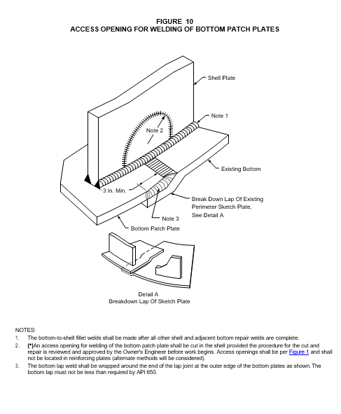
- Existing tank bottom constructed without a butt welded annular plate - Figure 9 and Figure 10.
- (*)When the entire bottom is to be replaced, the foundation shall be evaluated and repaired or modified, as necessary, in accordance with EP 4-2-10. The tank bottom plate design shall be in accordance with EP 9-1-1, except that annular plates are required for all tank sizes. Annular plates for double-bottomed repair shall extend 2-3/4 + 1/4 inches outside of the tank shell. The general procedure for retrofitting with a double tank bottom shall be as given below. The actual procedure shall be submitted to the Owner's Engineer for review and approval:
- The tank shall be gas freed and cleaned.
- All tank foundation repairs shall be completed, as required, in accordance with EP 4-2-10.
- Clearly visible holes in the existing bottom shall be sealed with a lining material compatible with the expected service, in accordance with EP 10-3-7.
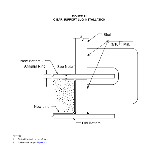
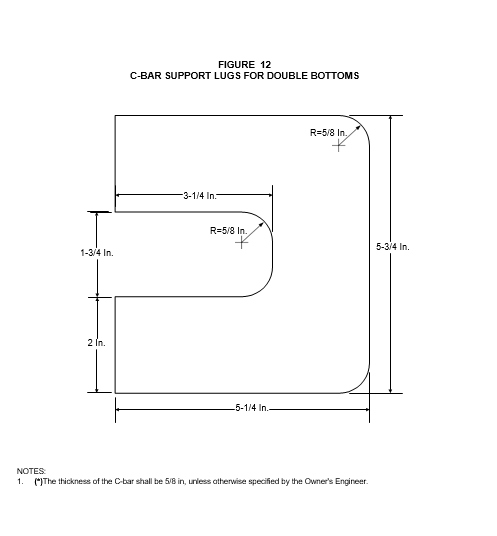
- (*)C-bar lugs shall be installed completely around the circumference of the tank in accordance with Figure 11. The maximum spacing shall be 10 feet. C-bar lugs shall be in accordance with Figure 12, unless otherwise approved by the Owner's Engineer.
- (*)Nozzles and other attachments that are in the path of the expected shell slot shall be removed and set aside for re-installation. The minimum clearance to be maintained between the shell slot and any attachment weld shall be 1.25 inches for manways up to 36- inch diameter, 1.75 inches for shell nozzles up to 36 inch diameter and 3 inches for butt- welded patches. Low-type attachments shall be removed in every case. When flush-type attachments are encountered the Owner's Engineer shall be consulted to determine the procedure for their removal and re-installation.
- A horizontal slot shall be cut parallel to the existing tank bottom using a track-guided torch. The slot shall be nominally 1/2 inch wider than the thickness of the new annular plate. The edges of the slot shall be straight and level to within ±1/8 inch in a 3 foot arc measured on the shell. The nominal dimension between the top of the existing tank bottom and the bottom of the slot shall be in accordance with EP 4-2-10. The slot shall be ground to remove burrs and slag.
- Fill materials, flexible membrane liners and cathodic protection shall be installed in accordance with EP 4-2-10.
- New annular plates shall be installed through the slot and welded in accordance with EP 9- 1-1 and EP 9-1-2. Remaining plates shall be brought in through the door sheet.
- After all annular plates have been installed, C-bars shall be removed and any damage to the shell resulting from temporary support attachments shall be repaired.
- Remaining bottom plates shall be welded in accordance with EP 9-1-1 and EP 9-1-2.
- Shell attachments shall be re-installed, maintaining the weld clearances required by this Practice.
- After the hydrotest, the underside of the new bottom shall be sealed to the remaining stub of the shell in accordance with Figure 18 of EP 4-2-10.
- Roof support legs shall bear on ¼-inch thick plates installed on the new bottom. Legs shall be suitably shortened to account for the height between the old and new bottoms.
- Bottom sumps shall be in accordance with the following requirements.
- New bottom sumps shall be located subject to restrictions in Table 1.
- Existing sumps shall be moved if the distance between the shell wall and the nearest sump to bottom-weld is less than 24 inches. The new location of sumps that are moved shall meet the requirements of Table 1.
- No part of a sump-to-bottom weld may be closer than 12 inches from an annular plate.
- (*)Written procedures for performing hot work on tank bottoms with probable or actual flammable vapors or liquids present shall be developed by the contractor and shall include the following applicable requirements. These written procedures shall be submitted to the Owner's Engineer for approval prior to the commencement of any work.
- Minor Repairs (defined as welding of pits, patches, bracing columns, etc.)
- Drill and tap (NPS 1/2) the floor plate adjacent to repair areas.
- Connect inert gas to taps. A pressure control valve with a flow indicator should be installed to prevent over-pressuring the bottom.
- Establish a flow of inert gas under the bottom in the vicinity of proposed welding.
- Continuously monitor the area for oxygen level (19.5 to 22.5 percent) and explosive atmosphere. Consideration shall also be given to increasing the air flow in the tank.
- When welding is finished, stop the inert gas flow, remove the tubing for inert gas, plug taps, check for oxygen level and explosive atmosphere and, provided atmosphere is acceptable, back weld promptly before moving to another area.
- Perimeter Repairs (defined as repairs near the shell)
- Remove lower insulation near repair area.
- Excavate under the edge of the tank, 12 inches beyond the hot work. The excavation shall be large enough for a person to work. Continuously monitor for oxygen level and explosive atmosphere.
- Seal all openings between the bottom plate and the foundation by packing with mud or another suitable substance. Check the seal periodically and limit walking on the tank bottom to protect this seal.
- Use vapor indicators to check the excavation and the seal between bottom and foundation.
- Before starting repairs and while repairs are in progress, monitor the surrounding area, including the excavation and tank interior, for oxygen level and explosive atmosphere.
- Vent the excavation, if necessary.
- When repairs are completed, remove the mud seal and promptly refill the excavation with material equivalent to the existing foundation materials and meeting the requirements of EP 4-2-10.
- Double Bottoms
- Place liner, sand, and cathodic protection on the old bottom, as required by EP 4-2-10, prior to any hot work.
- Before starting repairs and while repairs are in-progress, monitor the tank interior for oxygen level and explosive atmosphere.
- Install the second bottom.
- Sectional Repairs (defined as repair of large bottom quadrants)
- Cold cut the section and remove. Continuously, apply coolant to the cutting edges of tools.
- Excavate under the bottom section that has been removed to a depth and extent dictated by environmental and safety requirements, but at least six inches in depth. Refill the excavation with materials equivalent to the existing foundation materials and meeting the requirements of EP 4-2-10.
- Continuously monitor for oxygen level and explosive atmosphere while placing new floor plates.
- Repair of Fixed Roofs
- Supported cone roofs and self-supported roofs shall be repaired to meet the requirements of EP 9-1-1.
- (*)Designs for roof support system modifications required to strengthen a tank being placed into higher temperature service shall be submitted to the Owner's Engineer for approval.
- Repair of Floating Roofs
Repairs to floating roofs (both external and internal) shall be made as necessary to insure that the condition of the roof meets or exceeds its original condition.
- Repair or Replacement of Floating Roof Perimeter Seals
Repair or replacement of floating roof perimeter seals shall be in accordance with EP 9-1-3.
- Hot Taps
Hot taps shall meet the additional requirements of EP 5-7-1.
- Requirements for Riveted Tanks
- In addition to all other applicable requirements of this Practice, repairs to riveted tanks shall comply with the requirements of this section.
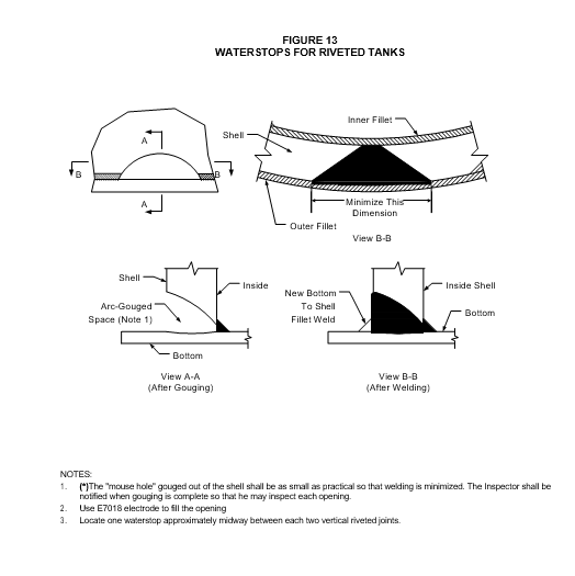
- Waterstops when required shall be in accordance with Figure 13.
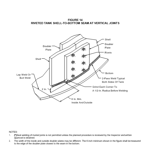
- The edge of each "doubler" plate within 2 inches of the bottom shall be ground to a 1/2 inch radius before any shell to bottom welding occurs, see Figure 14.
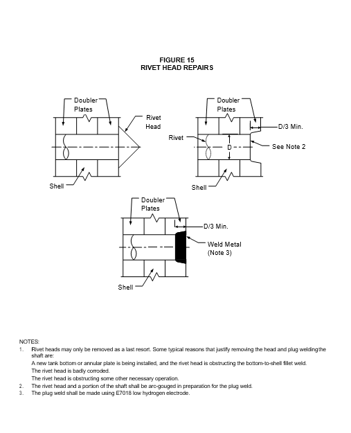
- Rivet heads which obstruct the path of the horizontal slot in the shell or interfere with the installation or welding operations at the bottom-to-shell fillet weld shall be removed and their shafts weld-reinforced in accordance with Figure 15.
- (*)Each riveted vertical seam and riveted reinforcing pad shall be sandblasted to a near white finish and epoxy coated from the floor to approximately 4 feet up the shell after all welding near the seam has been completed. Other riveted seams that may have suffered damage due to welding or other operations shall also be sandblasted and coated when specified by the Owner's Engineer. The epoxy coating shall extend across the full width of the doubler plate (covering all rivet heads), plus at least 6 inches on each side of the doubler plate and 6 inches onto the tank bottom.
- The epoxy coating on riveted seams and reinforcing pads shall be applied to both the inside and outside surfaces of the tank. The coating shall be per EP 10-3-7.
DISMANTLING AND RECONSTRUCTION (API 653, SECTION 8)
- General
Hydrostatic testing requirements including the settlement benchmark shall be in accordance with EP 9-1-1 and EP 4-2-10, except that the duration of the hydrotest shall be 24 hours minimum.
- Cleaning and Gas Freeing
- Cleaning and gas freeing of tanks shall be in accordance with API 2015, API 2015A, API 2015B, API 2201, API 2207 and API 2217.
- (*)Written cleaning and gas freeing procedures shall be submitted to the Owner's Engineer for approval prior to the commencement of any work.
- Dismantling Methods
- Bottoms for reconstructed tanks shall meet all design and fabrication requirements of EP 9-1-1. Reconstructed tanks with sketch plates shall be redesigned and configured with annular plates. The annular plate material shall have equal or exceed the strength and toughness of the shell plate material.
- The existing shell to bottom weld shall not be used.
- (*)Written dismantling procedures and drawings showing piece mark locations shall be prepared by the Contractor and submitted to the Owner's Engineer for approval prior to the commencement of work.
- Reconstruction
- (*)Written reconstruction procedures shall be prepared by the Contractor and submitted to the Owner's Engineer for approval prior to the commencement of work.
- The foundation for reconstructed tanks shall be in accordance with EP 4-2-7.
- Welding of reconstructed tanks shall be in accordance with the applicable requirements of EP 9-1-1 and EP 9-1-2.
- 11.5 Dimensional Tolerances
Foundation tolerances shall be in accordance with EP 4-2-7.
12.0 WELDING (API 653, SECTION 9)
Welding for repair and reconstruction of tanks shall be in accordance with EP 9-1-1 and EP 9- 1-2.
EXAMINATION AND TESTING (API 653, SECTION 10)
- Nondestructive Examination
- Nondestructive examination procedures, qualifications and acceptance criteria shall be in accordance with EP 9-1-1.
- Inspection requirements for new shell penetrations installed when the tank is not in service shall be in accordance with EP 9-1-1. Inspection requirements for hot taps shall be in accordance with EP 5-7-1.
- Completed repairs of fillet welds shall be examined over their full length by visual as well as by magnetic particle or liquid penetrant methods.
- Areas where weld projections (remaining after removal of temporary attachments) have been ground flush with the shell shall be examined by visual as well as magnetic particle or liquid penetrant methods.
- Completed welds of temporary or new permanent attachments, for all shell materials, shall be examined by visual as well as by magnetic particle or liquid penetrant methods.
- New welding on the bottom-to-shell joint shall be inspected for its entire length by a right-angle vacuum box and a soapy solution or by applying light diesel oil to the unwelded side opposite the first weld pass made, see EP 9-1-1. The oil shall be allowed to stand at least 4-6 hours (preferably overnight) and then the weld inspected for "wicking" action. Excess oil shall be removed before the weld is completed.
- Shell nozzle and manhole reinforcing plates shall be air-tested in accordance with EP 9-1-1.
- Radiographs
- The number and location of radiographs shall be in accordance with API 653 and the following additional requirements.
- For reconstructed tanks, the outer 6 inches of each butt-welded annular plate joint shall be radiographed. For tank repairs, the outer 6 inches of 50% of butt-welded annular plate joints shall be radiographed. These requirements also apply to annular plates with back-up bar joints.
- Circumferential and longitudinal butt welds in nozzles and manholes fabricated from pipe or plate, shall be 100% radiographed. Radiography of the shell to nozzle joint is not required.
- (*)For circular shell insert plates less than two feet in diameter, one radiograph shall be taken. For circular replacement plates greater than two feet, a minimum of two radiographs or that specified by the Inspector shall be taken.
- (*)For square or rectangular shell insert plates (including door sheets) with a perimeter of less than 10 feet, one radiograph shall be taken in a vertical joint, and one in a horizontal joint. For square or rectangular replacement plates with a perimeter greater than 10 feet, a minimum of one radiograph in each vertical and horizontal seam or that specified by the Inspector shall be taken.
- For square or rectangular shell insert plates, all rounded corners shall be radiographed.
- For circular, square or rectangular shell insert plates, all junctions between the repair welds and the existing welds shall be radiographed.
- Acceptance criteria for all radiographs shall be per EP 9-1-1.
- The Inspector shall have complete access to both the repair and original radiographs.
- Hydrostatic Testing
Procedures for hydrostatic testing shall be in accordance with EP 9-1-1 except that the duration of the test shall be a minimum of 24 hours. Settlement monitoring shall be in accordance with EP 4-2-10.
- Leak Tests
- New or altered reinforcing plates of shell penetrations shall be air leak tested in accordance with EP 9-1-1.
- New or replaced primary roof drains for external floating roof tanks shall be tested per EP 9-1-
- Prior to the test, the drain shall be flushed through to ensure the absence of any internal obstructions.
- Measured Settlement During Hydrostatic Testing
A settlement benchmark shall be completed prior to and after hydrostatic testing. The settlement benchmark shall be completed in accordance with the requirements of EP 9-1-1 and EP 4-2-10.
MARKING AND RECORDKEEPING (API 653, SECTION 11)
- The contractor shall certify in writing that repairs, alterations or reconstruction, as applicable, have been performed in compliance with this Practice.
- (*)All record keeping information including calculations, and construction and repair drawings shall be submitted to the Owner's Engineer for review and approval. The Contractor shall resolve all comments and unresolved issues cited by the Owner's Engineer, if any. After approval, these records shall become a part of the permanent tank inspection records.
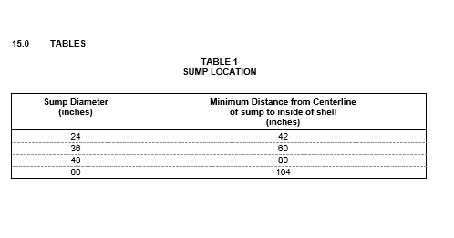
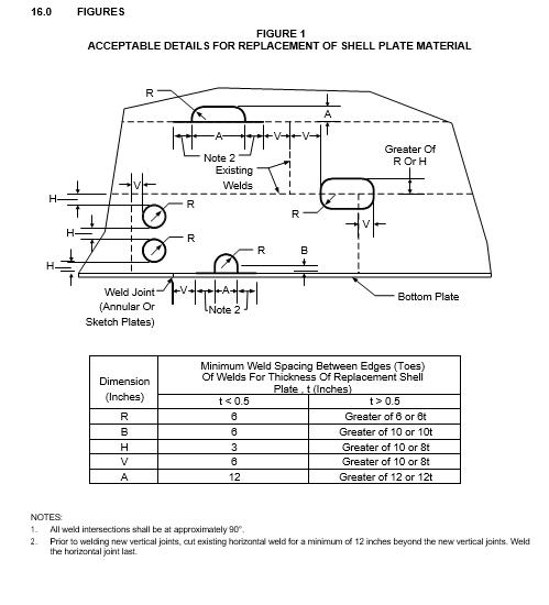
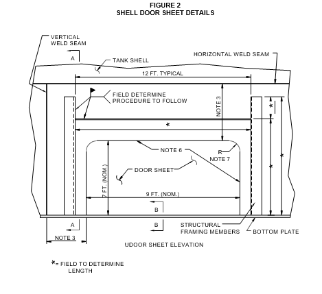
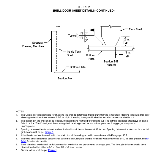
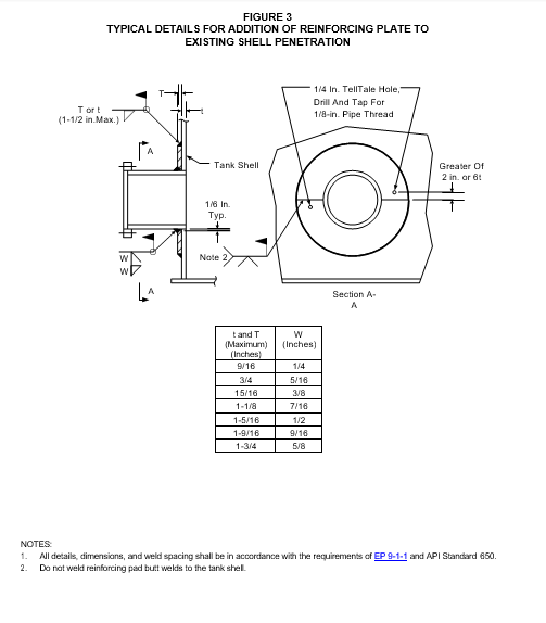
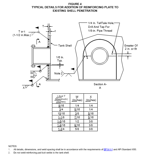
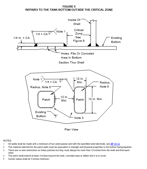
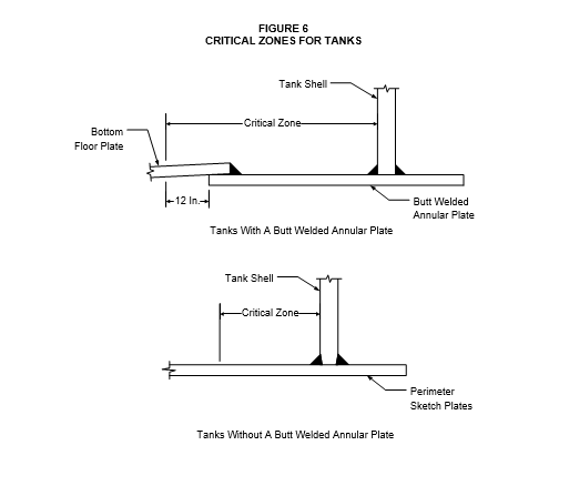
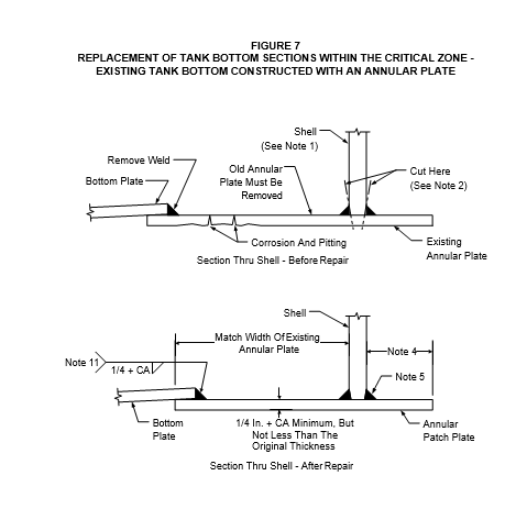
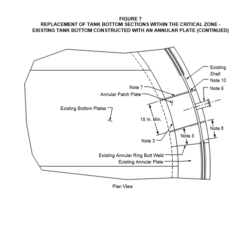
FIGURE 7
REPLACEMENT OF TANK BOTTOM SECTIONS WITHIN THE CRITICAL ZONE - EXISTING TANK BOTTOM CONSTRUCTED WITH AN ANNULAR PLATE (CONTINUED)
NOTES:
- The shell plate in the area of the repair must be in good condition in order for this repair method to be used.
- Disengage the bottom plate (in the area to be repaired) from the shell by cutting with an arc gouge. Every effort shall be made to minimize damage to the shell.
- Lift existing bottom plate to obtain necessary access to complete the existing annular plate to annular patch plate weld. Alternatively the existing bottom plate can be removed to provide access to complete this weld.
- The bottom extension outside the tank shell shall be trimmed to match the existing bottom outer edge provided that at least 2 inches project beyond the weld attaching the bottom to the shell.
- The shell-to-annular plate weld shall be per EP 9-1-1.
- The shell-to-annular plate weld shall be removed for at least 12 inches beyond the access opening in the tank shell, see Figure 1 and Note 10.
- Weld joint design shall be per EP 9-1-1. The use of a backing strip is recommended.
- The minimum distance between an annular patch plate butt weld and an existing annular ring butt weld shall be 6 inches.
- Low-type shell nozzles located in the repair area shall be removed and later reinstalled.
- Provide an access opening in the shell per Figure 8 for welding of the annular patch plate.
- Two pass fillet weld is required.
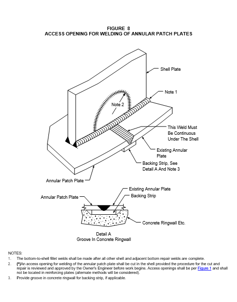
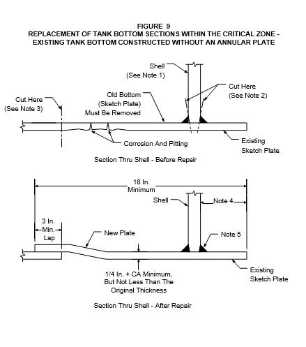
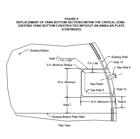
FIGURE 9
REPLACEMENT OF TANK BOTTOM SECTIONS WITHIN THE CRITICAL ZONE - EXISTING TANK BOTTOM CONSTRUCTED WITHOUT AN ANNULAR PLATE (CONTINUED)
NOTES:
- The shell plate in the area of the repair must be in good condition in order for this repair method to be used.
- Disengage the bottom plate (in the area to be repaired) from the shell by cutting with an arc gouge. Every effort shall be made to minimize damage to the shell.
- The cut in the bottom plate shall be at least 3 inches beyond the hole, corroded area or defect so that a minimum of 75% of the original plate thickness is available under the new repair welds.
- The bottom extension outside the tank shell shall be trimmed to match the existing bottom outer edge provided that at least 2 inches project beyond the weld attaching the bottom to the shell.
- The shell-to-bottom plate weld shall be per EP 9-1-1.
- The bottom-to-shell welds shall be removed for at least 12 inches beyond the access opening in the tank shell, see Figure 1 and Note 10.
- The edge of the welds on adjacent patch plates may not be closer than 12 inches from each other or from the nearest bottom weld.
- The corners of the bottom cutout shall have at least a 3-inch radius. However, when one or more edges of the patch coincide with a bottom seam, the corner on that side of the patch should be left square (no radius).
- Low-type shell nozzles located in the repair area shall be removed and later reinstalled.
- Break down new patch plate to minimize shell to patch plate gap. Provide an access opening in the shell per Figure 10 for welding of the patch plate.
- Two pass fillet weld is required.
© 2026 Inflection Point Engineering, LLC. All rights reserved. The content of this page — including calculation methods, reference data, written analysis, interactive tools, and source code — is the intellectual property of Inflection Point Engineering, LLC and is protected under applicable copyright, trademark, and trade secret laws. Unauthorized reproduction, redistribution, modification, or derivative use in whole or in part is prohibited without prior written consent.
Disclaimer. This material is provided for informational and educational purposes only and does not constitute professional engineering advice. Calculations, reference data, and methodologies are based on published standards and accepted engineering practice but are not a substitute for engineering judgment, site-specific analysis, or review by a licensed Professional Engineer. Inflection Point Engineering, LLC makes no warranties, express or implied, regarding the accuracy, completeness, or fitness for a particular purpose of any content presented here, and shall not be liable for any direct, indirect, incidental, or consequential damages arising from its use. Users assume all risk associated with applying this content to real-world design, operations, or decisions.
© 2026 Inflection Point Engineering, LLC. All rights reserved.