 Section 9 — Storage Tanks
Accessories for Atmospheric Storage Tanks
IPE Engineering Practice IPE-EP-9-1-4
Document number: IPE-EP-9-1-4 · Section: 9 — Storage Tanks
SCOPE
- This Practice covers general requirements for accessories and appurtenances for atmospheric storage tanks.
- Any deviation from this Practice must be approved by the procedure described in EP 1-1-3.
- An asterisk (*) indicates that a decision by the Owner or Owner's Engineer is required or that additional information is furnished by the Purchaser.
- A revision bar indicates all changes made to this Revision.
2.0 REFERENCES
The latest edition of the following standards and publications are referred to herein.
STANDARDS AND PUBLICATIONS
| Engineering Practices |
|---|
| EP 1-1-3 Deviations to Engineering Practices EP 3-5-4 Foam Fire Protection Systems EP 4-5-3 Auxiliary Structures for Operation and Maintenance EP 5-5-1 Piping Fabrication EP 9-1-1 DS Atmospheric Storage Tanks Data Sheet EP 11-3-1 Insulation Design EP 11-3-4 Insulation Application - Storage Tanks and Spheres EP 12-1-1 Control Systems EP 12-9-1 Instrumentation for Above Ground Storage Tanks |
| API Standards |
| Std 650 Welded Steel Tanks for Oil Storage Std 2000 Venting Atmospheric and Low Pressure Storage Tanks |
| ANSI Standard |
| Z35.1 Industrial Accident Prevention Signs |
DEFINITIONS
- Inspector - A Refining Company appointed engineer or inspector.
- Manufacturer - The recipient of a direct or indirect purchase order for materials and/or equipment. In this context, a direct order is one issued to a manufacturer by a contractor or the Owner. An indirect order is one issued to a manufacturer by a vendor (recipient of a direct order) for materials, fabricated components, or subassemblies.
- Owner - Refining Company.
- Owner's Engineer - A Refining Company appointed engineer.
- Purchaser - The party placing a direct purchase order. The purchaser is the Owner's designated representative.
GENERAL
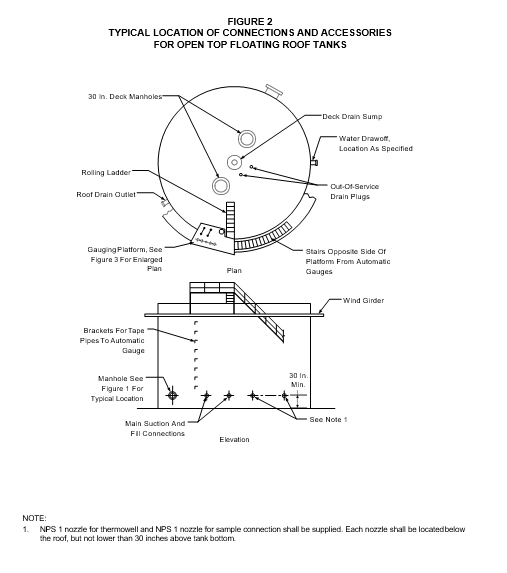
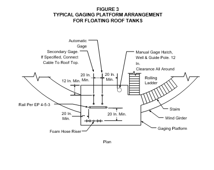
- (*)Unless otherwise specified by Owner's Engineer, connections and accessories shall be located per Figure 1 for fixed-roof tanks or per Figure 2 and Figure 3 for floating-roof tanks except for the following:
- The location of connections shall be altered if the specified location interferes with a weld seam that cannot be reoriented.
- Where a water draw-off or slop sump is located near the tank shell, the following requirements apply:
- The water draw-off and sump suction connection shall be 50 feet minimum (circumferential distance) from any oil suction or fill connection for tanks larger than 60-foot diameter, or 90 degrees minimum angle (measure around the tank shell), from an oil suction or fill connection for tanks smaller than 60-foot diameter.
- When a slop nozzle is required for crude tanks, it shall be located between 90 degrees and180 degrees (measured around the tank shell) from the tank outlet nozzle.
- Caution signs conforming to ANSI Z35.1 shall be provided to warn of nitrogen, toxic, or other dangerous materials in tanks. The signs shall be located at the foot of stairs and on dikes near accessways to tank.
VENTS FOR FIXED ROOF TANKS
- (*)Vent sizing shall be per API 2000. Open vents shall be of the goose-neck type and covered with a 4-mesh screen. The maximum pumping rate, and the need for additional venting capacity of tanks handling spiked crudes, those tanks fitted with heaters, and blending tanks blending with materials greater than 15 RVP will be specified by the Owner's Engineer.
- Pressure-vacuum vents shall be covered with a 4-mesh screen and shall be used when the following conditions apply:
- The stock stored has a flash point below 100°F.
- Temperature of the stored product is above or within 15°F of its flash point at the highest operating temperature.
- The stocks stored are valuable and have low vapor pressure such as alcohol.
- In areas when climatic conditions are such that the daily mean temperature falls below 30°F for periods exceeding 24 hours duration, pressure-vacuum vents shall be provided with non- freezing features including:
- Pallets with drip rings.
- Pallets with flexible diaphragms to prevent a metal to metal contact on seating surfaces.
- (*)Unless otherwise specified by the Owner's Engineer, pressure-vacuum vents shall be set to open at 1.30 inches of water pressure and vacuum, respectively. The capacity of pressure- vacuum vents shall be determined at 1.50 inches of water pressure and vacuum, respectively. This conforms to the use of the API minimum roof thickness of 3/16 inch.
- (*)Tank filling and emptying rates for sizing pressure-vacuum roof vents shall be specified by the Owner's Engineer on the Atmospheric Storage Tank Data Sheet, see EP 9-1-1 DS.
- In asphalt service, the following limitations shall apply:
- Screens shall not be used on goose-neck vents.
- Pressure-vacuum vents shall not be used except when the tank is blanketed with an inert gas system.
5.7 (*)Unless otherwise specified by the Owner's Engineer, flame arresters are not required.
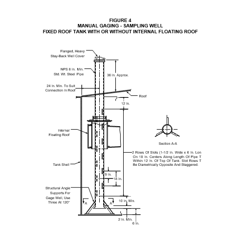
MANUAL GAGING - SAMPLING FOR FIXED ROOF TANKS
- Unless otherwise specified by the Owner's Engineer, for fixed roof tanks (with or without an internal floating roof) a manual gaging-sampling well per Figure 4 shall be used where the stored product, including intermediate storage, is specified as a "static accumulator". A gaging sampling well is not required where the stored product will not be a "static accumulator". In such cases, a gage hatch shall be installed on a roof manhole cover.
- If a manhole or a separate roof connection is used for gaging - sampling purposes it shall be located near a roof support.
- Unless otherwise specified by the Owner's Engineer, gaging hatches shall be per the following:
- The gaging hatch shall have a seal with corrosion resistant seats suitable for a pressure of 2 oz/in2. or the design pressure of tank, whichever is greater, and a heavy stay-back cover.
- The gaging hatch shall have an 8-inch minimum diameter.
REQUIREMENTS FOR FIXED ROOF TANKS WITH INTERNAL FLOATING ROOFS
- Tank shell air-circulation vents shall be provided per the following:
- Spacing and total open area of vents shall be per API 650, Appendix H.
- The vents shall be located above the seal of the internal floating roof (i.e., above the upper travel limit). Alternatively, the vents may be located on the tank roof provided their inlet overhangs the shell and they are designed such that the incoming air is deflected downward.
- (*)Unless otherwise specified by the Owner's Engineer, the fixed roof open vent shall have a minimum open area of 50 in2.
- Fixed roof or tank shell air-circulation vents shall be covered with coarse mesh screen with 1/2- inch openings, and provided with weather shields.
- Inspection hatches shall be provided in the tank roof per API 650, Appendix H, to permit visual inspection of the seal region. A guard railing, per Section 14.0, shall be installed at the outside edge of each inspection hatch.
- (*)Unless otherwise specified by the Owner's Engineer, designs which combine inspection hatches with tank shell vents (located on the tank roof) are acceptable.
- Overflow slots shall be provided to prevent overfilling the tank above its net capacity and shall be sized for the maximum filling rate. The slots shall be covered with coarse mesh screen with 1/2-inch openings, and shall be provided with weather shields.
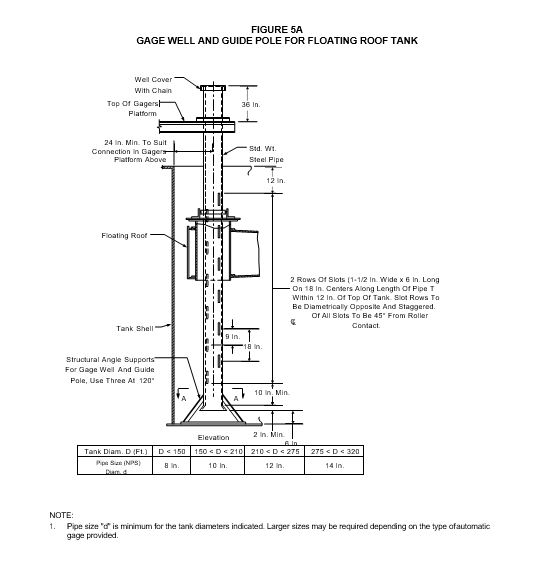
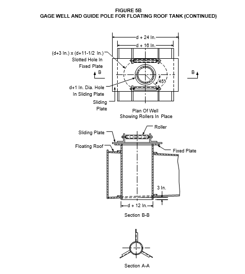
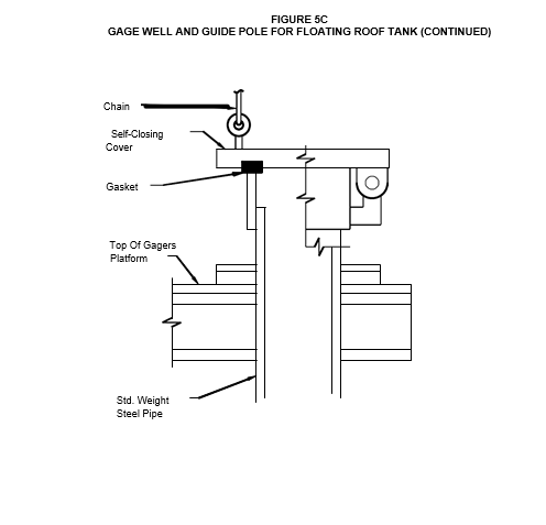
GAGE WELL AND GUIDE POLE FOR FLOATING ROOF TANKS
- A combination gage well and guide pole assembly per Figure 5 shall be provided for each floating roof tank whether or not the tank is to be equipped with an automatic gage.
- The pipe shall be located within easy reach for personnel standing on the gauger's platform. The top of the pipe shall terminate about 3 feet above the platform grating and shall be equipped with an 8 inch, spark-resistant, self-closing gauge hatch.
- (*)The tank Manufacturer shall provide a float and seal arrangement, inside the pipe, designed to minimize the escape of vapors. The float shall have a light chain or cable attached to it so that it can be removed and re-installed from the gauger's platform. Alternate designs may be submitted for approval by the Owner's Engineer.
WATER DRAWOFF CONNECTIONS
- Tanks in hydrocarbon service shall be provided with a minimum of one water drawoff connection per EP 9-1-1.
- (*)Unless otherwise specified by the Owner's Engineer, water sumps and water drawoff pipe shall be supplied in accordance with the following criteria:
- For tanks over 20 ft. in diameter, a water sump is required. The sump may be any shape, provided it has a volume at least equal to the volume of the sump specified in API 650. The end of the drawoff pipe shall be 4 inches above bottom of sump.
- For tanks 20 ft or less in diameter, a sump is not required. The inlet end of the water drawoff pipe shall be 2 inch above the bottom, except in the case of "cone down" bottom tanks. In such cases, the end of the pipe shall be 4 inches above the bottom.
INSTRUMENTS
- (*)Gage types and installation shall be per EP 12-9-1, and specified by the Owner's Engineer. A minimum of one level gaging instrument per tank, readable from grade, shall be provided.
- For tanks in asphalt service, provision shall be made to automatically shut off heaters when they became exposed above the liquid level. The type of level control and installation requirements shall be specified by the Owner's Engineer and shall be per EP 12-1-1.
*
- Connections for temperature indication shall be provided as follows:
- Fixed roof tanks without internal floating covers. An NPS 1 threaded connection shall be furnished for a thermowell installation, see Figure 1. Supply and installation of thermowell shall be by purchaser or vendor, as specified.
- (*)The type and method of installation of the temperature measuring device shall be specified by the Owner's Engineer and shall be per EP 12-9-1 for floating roof tanks and fixed roof tanks with internal floating covers.
TANK HEATERS
- Tank heating coils and associated piping shall be designed, fabricated, inspected and tested in accordance with EP 5-1-1.
- Internal heater support design shall take into account differential thermal expansion, shell radial displacement and rotation of shell to bottom junction.
- Where tanks are heated by means of a fired heater having flue tubes through the shell, the liquid within the tank shall be maintained at a minimum level of 6 inches above the tops of the flue tubes by installing the main suction nozzle and internal suction pipe openings at elevations high enough to prevent the tank liquid from being pumped below this level. If an auxiliary low suction connection is provided, the low suction nozzle, valve, and piping shall be painted red, the valve shall be car-sealed closed, and a warning sign (per ANSI Z35.1) installed on the valve instructing the operator to shut down the fired heater before breaking the seal to open the valve. The heaters shall not be fired until the low suction valve is car-sealed closed and the tank liquid level is at least 6 inches above the tubes.
- All tanks with internal heaters shall be equipped with warning signs per ANSI Z35.1.
INSULATION
- Insulation design for tanks shall be per EP 11-3-1.
- Installation of tank insulation shall be in accordance with EP 11-3-4.
- Tank attachments required for support of insulation shall be supplied and installed by the tank Manufacturer. Support clips welded to the tank and insulation support rings shall be fabricated from the same material as the tank.
- (*)Installation of insulation shall be by others, unless otherwise specified by the Owner's Engineer.
FOAM SYSTEMS
- Requirements for foam systems for atmospheric storage tanks are covered in EP 3-5-4.
- (*)When flanged connections are specified by the Owner's Engineer for future installation of foam chambers, these connections shall be blanked with a 1/4 inch thick blind flange, to provide a gas tight connection.
AUXILIARY STRUCTURES FOR OPERATION AND MAINTENANCE
- The design of stairways, ladders, platforms, walkways, guard railings and other auxiliary structures for operation and maintenance shall be in accordance with EP 4-5-3.
- All external attachments to shell and roof tops shall be continuously welded to prevent crevice corrosion and rust streaking.
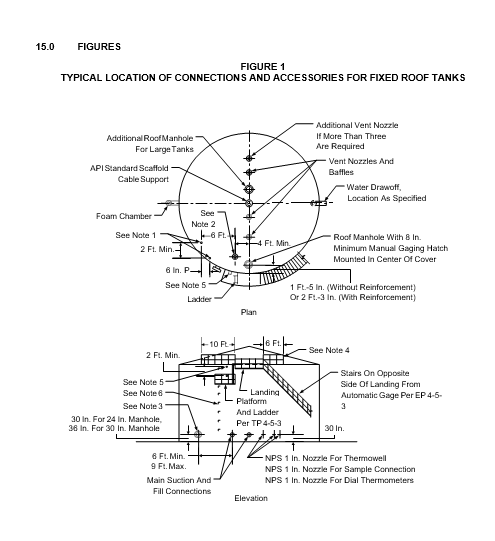
FIGURE 1
TYPICAL LOCATION OF CONNECTIONS AND ACCESSORIES FOR FIXED ROOF TANKS (CONTINUED)
NOTES:
- NPS 1-1/2 nozzles for gas blanketing shall be supplied; locations may vary slightly to clear internal obstructions.
- Automatic gage; if practicable, locate the gage and shell manhole on upwind (prevailing wind) side of tank.
- Locate one shell manhole in shown position, and others equally spaced around tank.
- The handrail must extend at least 3 feet past the gas blanketing connection and other roof connections, on each side.
- (*)Two NPS 1 diameter nozzles for high level alarm shall be supplied. The top nozzle shall be located just below the roof angle, unless otherwise specified by the Owner's Engineer.
- Brackets for the gage tape pipe, gas blanketing pipe and level alarm conduit, shall be on the opposite side of landing from stairs.
© 2026 Inflection Point Engineering, LLC. All rights reserved. The content of this page — including calculation methods, reference data, written analysis, interactive tools, and source code — is the intellectual property of Inflection Point Engineering, LLC and is protected under applicable copyright, trademark, and trade secret laws. Unauthorized reproduction, redistribution, modification, or derivative use in whole or in part is prohibited without prior written consent.
Disclaimer. This material is provided for informational and educational purposes only and does not constitute professional engineering advice. Calculations, reference data, and methodologies are based on published standards and accepted engineering practice but are not a substitute for engineering judgment, site-specific analysis, or review by a licensed Professional Engineer. Inflection Point Engineering, LLC makes no warranties, express or implied, regarding the accuracy, completeness, or fitness for a particular purpose of any content presented here, and shall not be liable for any direct, indirect, incidental, or consequential damages arising from its use. Users assume all risk associated with applying this content to real-world design, operations, or decisions.
© 2026 Inflection Point Engineering, LLC. All rights reserved.