 Section 9 — Storage Tanks
Tank Roof Seal
IPE Engineering Practice IPE-EP-9-1-3
Document number: IPE-EP-9-1-3 · Section: 9 — Storage Tanks
SCOPE
- This Practice covers requirements for the design, fabrication, and installation of primary and secondary roof seals for internal and external floating roof tanks.
- This Practice is applicable to new seal installations and/or the replacement of existing seal installations. This Practice supplements the requirements of API 650, Appendix C.
- Any deviation to this Practice must be approved by the procedure described in EP 1-1-3.
- An asterisk (*) indicates that a decision by the Owner or Owner's Engineer is required, or that additional information is furnished by the Purchaser.
- A revision bar indicates all changes made to this Revision.
2.0 REFERENCES
The following standards and publications are referred to herein.
STANDARDS AND PUBLICATIONS
| IPE Engineering Practices |
|---|
| EP 1-1-3 Deviations to IPE Engineering Practices EP 3-5-4 Foam Fire Protection Systems EP 9-1-3 C Tank Roof Seals Inspection Checklist EP 13-15-1 Equipment Grounding Details |
| API Standard |
| Std 650 Welded Steel Tanks for Oil Storage |
| ASTM Standards |
| D543 Carbon and Low-Alloy Steel Forgings Requiring Notch Toughness Testing for Piping Components D751 Pressure Vessel Plates, Carbon Steel, Improved Transition Properties D814 Pressure Vessel Plates, Carbon Steel, for Moderate- and Lower-Temperature Service D2240 Seamless Carbon Steel Pipe for Atmospheric and Lower Temperatures |
DEFINITIONS
- AQMD - Air Quality Management District, or other local air quality office, having jurisdiction over primary and secondary seal installation. In the absence of a local AQMD, or if EPA requirements are more stringent, the EPA standards shall prevail. AQMD standard shall prevail over EPA standards if they are more stringent.
- Contractor - Company or business that agrees to furnish materials or perform specified services at a specified price and/or rate to the Owner.
- Inspector - A Inflection Point Engineering, LLC appointed engineer or inspector.
- Manufacturer - The recipient of a direct or indirect purchase order for materials and/or equipment. In this context, a direct order is one issued to a manufacturer by a contractor or the Owner. An indirect order is one issued to a manufacturer by a vendor (recipient of a direct order) for materials, fabricated components, or subassemblies.
- Owner - Inflection Point Engineering, LLC
- Owner's Engineer - A Inflection Point Engineering, LLC appointed engineer.
- Purchaser - The party placing a direct purchase order. The purchaser is the Owner's designated representative.
- Replaceable-in-service Shoe System - A "replaceable-in-service" shoe system is one in which the seal attachment points are positioned above the liquid level to facilitate disconnection and removal without working below the liquid surface.
DATA FURNISHED BY PURCHASER
- The Purchaser shall provide the following information:
- Procurement documents
- Specification of seal type in accordance with the requirements of this Practice and IPE Engineering Services Recommended Environmental Guidelines.
- All applicable IPE Engineering Practices and authorized deviations per EP 1-1- 3, as applicable.
- Drawings showing the tank shell, orientation of the roof and the location of all shell and roof appurtenances which may interfere with the installation or operation of the seal.
- As a minimum, a schedule for the receipt of the following information and the required number of copies shall be specified by the Purchaser:
- Details of seal attachment to floating roof, including description of all materials required.
- Details and dimensions of primary and secondary seal construction and positioning devices including procedures for making fabric splices.
- Nonmetallic and metallic seal materials to be used, including a detailed specification and compatibility of all elastomeric materials with the specified service.
- Seal expansion and contraction capabilities, including all calculations and maximum circumferential variations.
- Technical specifications of elastomeric materials used, demonstrating compatibility with the specified service. Particular attention shall be given to tanks in MTBE service. Flame- spread rating of all seal fabric and elastomeric materials shall also be provided. These materials shall not sustain combustion in the absence of a live flame.
- Details for installation of primary and secondary seals, as applicable.
- The annular space variation accommodated by each proposed roof seal.
- Details of the proposed seal installation at fixed roof column openings, gage well opening, and for the roof-to-shell area.
- (*)New working capacity of the tank. Unless otherwise specified by the Owner's Engineer, the safe oil height for fixed roof tanks will be 6 inches below the bottom edge of the lowest rafter or support.
MANUFACTURER'S RESPONSIBILITY
- General
- The Manufacturer shall assume responsibility for designing and supplying the tank roof seal in accordance with the specified design conditions.
- The Manufacturer shall provide the information described in paragraph 4.2. The number of copies and schedule shall conform to the Purchaser's requirements.
- (*)The Manufacturer shall take the rim space and related tank measurements to ensure that the seal will function correctly. Access to the tank roof must be cleared with the Owner's Engineer before measurements are taken or work is begun.
- Where work on the primary seal is specified, the work shall include removal and reinstallation of the existing secondary seal, if removal is necessary to complete the work.
- (*)Where the annular space variation exceeds the normal variation range of the seal system design, the Manufacturer shall notify Owner's Engineer and modify or adjust the design as necessary, to maintain a tight seal in that location. The Owner's Engineer shall approve these modifications.
- The Manufacturer shall certify on the drawings furnished to Owner's Engineer that the seal design and materials furnished will meet the requirements of this Practice.
- Conflicting Requirements
The Manufacturer shall refer all conflicting requirements contained in the Purchase Order to the Purchaser in writing for clarification and resolution before proceeding with the manufacture or procurement of the affected part. The Manufacturer is not at liberty to assume which requirements govern.
- Quality Control
- The Manufacturer shall ensure that technical and quality assurance requirements specified in the inquiry and purchase documents are applied to all materials, equipment and services provided by subcontractors and to any free-issue materials.
- To assure a quality installation, it is recommended that the seal Manufacturer, or his authorized agent, perform the installation of the primary and/or second seals.
- Packaging and Shipping
- The Manufacturer shall be responsible for suitably packaging all seal components to protect them from damage or loss during handling and shipment in accordance with the Purchase Order and the following requirements:
- All material and methods of packing shall conform to the specifications referenced in the Purchase Order.
- Packages shall include designated lifting points.
- Each package, crate, or bag shall be durably marked with the receiving address, Purchaser's Item Number, and the complete Purchase Order Number. As a minimum, all markings shall be in the English language.
- The Manufacturer shall include a packing list in each shipment, listing the contents of each box, crate, bag, and skid by assembly piece mark, individual piece mark, or by tank number. The list shall state whether the contents constitute complete or partial shipment.
- The Manufacturer shall provide any special protection or packaging, and details of any storage, shelf life, or maintenance instructions which are not within the scope of the Purchase Order but which pertain to the Manufacturer's guarantee or are otherwise necessary for protection of the tank.
DOCUMENTATION
- After the Owner's Engineer approval and final revision, approved documentation shall be furnished to the Purchaser. As a minimum, the information to be included in the documentation shall include those items listed in paragraph 4.2. The Purchaser will specify the number of copies of approved documentation.
- If modifications to the approved documentation are required during fabrication or installation of the tank seal, one reproducible and four copies of "as-built" documentation (only those affected) shall be issued to the Owner's Engineer. Modifications shall not be made to the approved design without receiving approval from the Owner's Engineer and the Inspector.
MATERIALS
- Nonmetallic Seal Components
- Elastomeric seal components shall be compatible with the product stored in the tank. Consideration should be given to the selection of elastomeric seal components that will be compatible with not only current, but future anticipated changes in product storage, see Table 1.
- Recommended properties for elastomers are shown in Table 2.
- Metallic Seal Components
- (*)Unless otherwise specified by the Owner's Engineer, materials for metallic seal components shall be in accordance with the requirement of this Practice.
- Primary Shoe Material - 18 gage Type 300 Series stainless steel shall be furnished.
- Primary Shoe Hanger System - All bolts and clamping bars used to attach the main and expansion joint seal fabric to the stainless steel shoes and to attach the seal fabric to the roof rim shall be made of Type 300 Series stainless steel. Bolts used to attach the main seal to the floating roof rim shall be 1-1/2 inches long to permit installation of a secondary seal by others at a later date. Aluminum and/or steel pop-rivets shall not be used in fabrication or installation of the primary seal.
- Replaceable-in-Service Shoe System - All metallic parts shall be fabricated of Type Series 300 Stainless steel. Nonmetallic parts such as gaskets shall be of polyethylene. Anti-rotational caps shall be of neoprene. Caulking material shall be butyl based.
- Non-Replaceable-in-Service Shoe System - Hanger arms shall be made of carbon steel and hot dipped galvanized after fabrication. Where tank inspection records show carbon steel, without the hot dipped galvanizing process, to have an acceptable operating life, the galvanizing process may be eliminated. Pins, bushings, retaining clips and springs shall be made of Type 300 Series stainless steel. Attachment clips mounted on stainless steel shoes shall be fabricated of Type 300 Series stainless steel. Attachment clips mounted on the floating roof rim shall be fabricated of 3/16-inch Type 300 Series stainless steel and shall be attached to the rim by a 3/16-inch fillet weld all the way around the clip.
- Secondary Seals - Galvanized pressure plates shall be furnished unless stainless steel plates are specified. All metallic parts, including bars, plates, sheets, pins, bolts, nuts and washers, etc. which are in contact with the stainless steel pressure plates shall be made of Type 300 Series stainless steel. Metallic parts not in contact with the stainless steel pressure plates shall be zincor cadmium-plated carbon steel. If stainless steel pressure plates are specified, the material shall be spring tempered to a quarter hard condition. Aluminum and/or steel pop-rivets shall not be used in fabrication or installation of the secondary seal system.
- Galvanized materials shall not be used for tank roof seal components in services where the zinc can dissolve and contaminate the product. Zinc contamination has been noted in jet fuel product supplied to military specification.
EXTERNAL FLOATING ROOF SEAL SPECIFICATIONS
- Type of Seal System to be Furnished
- (*)The Owner's Engineer will specify which of the following designs of primary seal systems is acceptable.
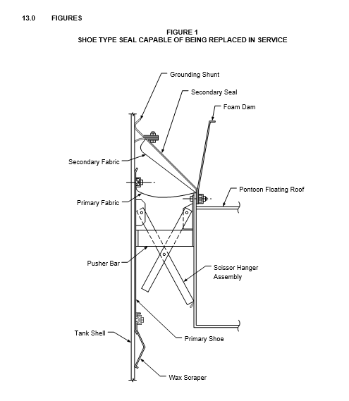
- A shoe-type seal capable of being replaced in service, see Figure 1.
- A shoe-type seal, not capable of being replaced in service.
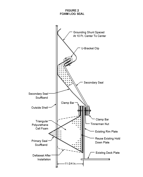
- Foam log primary seal (unless otherwise specified by the Owner's Engineer, this type of seal shall be used for internally coated tanks), see Figure 2.
- (*)A rim-mounted galvanized secondary seal system shall be installed unless otherwise specified by the Owner's Engineer.
- Design Requirements for All Seal Systems
- The design and construction of a seal assembly (primary and/or secondary) shall be approved for use by the local AQMD, and shall fully comply with the requirements of the local AQMD.
- Design and construction of the seal assembly shall allow the tank to overflow and then return to a liquid level that floats the roof below the top of the tank shell. This shall be accomplished without damage to any part of the tank or seal system, excluding damage that may be caused by the spilled portion of the tank contents. During such an occurrence, no manual attention shall be required to protect the tank or seal system.
- The seal assemblies shall be designed for the expansion and contraction requirements of the individual tank. Standard variations in the tank shell, roof travel and rotation about roof guides, and thermal expansion shall be incorporated in the design. The Manufacturer shall furnish the Owner's Engineer with the expansion and contraction capabilities of the seals, including design calculations. The Manufacturer shall also furnish with his bid the maximum circumferential variations (plus and minus) that the seal design can accommodate.
- The primary seal shall be secured to the floating roof rim plate in such a manner that the secondary seal can be removed without impairing the operation of the primary seal.
- Wedges shall not be used in fastening inter-shoe splices or main seal fabric. Seal fabric shall be bolted to the shoes with 3/8-inch diameter by 1-1/4-inch carriage bolts, installed in such a manner that a backup wrench will not be required for their removal.
- (*)The Manufacturer shall submit with bid documents for Owner's Engineer approval, the recommended procedure for joining fabric splices.
- Mechanical Shoe-type Seal Systems - Either Replaceable or Non-Replaceable While in Service
- The shoe geometry shall comply with the requirements of the local AQMD. The top edge of the shoe shall extend a minimum of 2 inches above the top edge of the roof rim. In addition, the bottom edge of the shoe shall extend into the liquid product a minimum of 2 inches and the top edge shall extend a minimum of 24 inches above the liquid surface.
- The length and angle of break or roll at the top and bottom of the shoes shall be adequate to prevent snagging on shell protrusions such as rivets, lapped seams, etc.
- (*)Unless otherwise approved by the Owner's Engineer, all hangers, weights or other devices that exert pressure against the shoes shall be below the seal. All shoes shall be supported in at least 2 locations so that no loading exists on the fabric between the shoes. The pressure exerted on the shoes shall be uniform around the roof and shall not greatly exceed the pressure required to hold the shoe against the shell.
- (*)All primary seal assembly shoes shall be supported at a minimum of 2 points along a horizontal line so that under no condition of loading is the connecting fabric between shoes required to provide vertical support. Horizontal thrust pushing the shoe against the shell shall be located at 2 additional points. If the shoe supports are attached to the upper portion of the shoe, the horizontal thrust points shall be at the lower portion; if the shoe supports are attached to the lower portion of the shoe, the horizontal thrust points shall be at the upper portion. Seal designs utilizing coil springs to provide horizontal thrust shall be reviewed and approved by the Owner's Engineer. The hanger system design shall prevent the catching and pinching of the primary seal fabric unless otherwise approved by the Owner's Engineer.
- (*)The main seal fabric shall be wide enough to allow for movement of the roof relative to the shoes at all roof levels. The Manufacturer shall calculate the minimum acceptable finished fabric width and shall submit the calculations to the Owner's Engineer for approval.
- Fabric vapor seals used with the mechanical shoe-type seal shall be continuous and gas tight. If the seal is immersed in the liquid, fabric splices shall be minimized. Immersed edges of the fabric, except small field cuts required for bolts, etc., shall be completely sealed by the synthetic coating material to prevent wick action occurring in the fibers. Fabric vapor seals shall be replaceable while the tank is in service.
- Expansion joint fabric shall be sealed to the primary seal fabric. There shall be no gaps between the seal fabric and shell as the expansion joint opens and closes. As necessary to close gaps caused by the primary seal contracting, "pillows" consisting of fabric-covered urethane foam may be installed between the tank shell and the fabric splice of the expansion joint and primary seal. Consideration shall be given to seal systems that do not require expansion joint fabric between the shoes.
- The Manufacturer shall make necessary cutouts for any shell appurtenances that might damage the shoes when the roof is on its low legs. Bolts heads, rivets, etc., shall not protrude from the shoe surface in contact with the tank shell.
- The seal system shall be electrically bonded to the roof. On tanks with united shells and with no rolling roof ladder, the Manufacturer shall install free hanging or reel-type grounds to ground the roof to the tank shell.
- Supplemental Requirements for Mechanical Shoe Seal Systems Which are Replaceable- In-Service
- The following supplemental requirements are in addition to those of Section 8.3.
- The seal design must be capable of local modification to close the annular space up to 3 inches greater than the normal design tolerance of +4.0 inches.
- When the annular space is at the design minimum, there must be at least 1 inch of space between the liquid in the tank and the vapor barrier portion of the seal assembly at all locations.
- The system shall have a shoe in contact with the shell; wipe or point-contact-type seal systems are not acceptable.
- Segments and/or the entire seal system must be capable of being replaced in service.
- The primary seal fabric, in installations without a secondary seal, must be able to support the weight of frozen rainwater without tearing.
- Secondary Seal Systems
- (*)The secondary seal shall be rim mounted. The design and construction details of the secondary seal assembly, including composition and manufacturer's designation of all seal fabrics, adhesives, wiper blades, and polyurethane foams, shall be submitted to the Owner's Engineer for approval prior to installation.
- The design of the secondary seal shall permit filling of the tank to the maximum fill height possible with the secondary seal retaining its effectiveness.
- The design shall be such that the secondary seal can be installed, removed, and repaired while the tank is in service.
- The design of the secondary seal shall provide grounding to the shell if any metallic parts of the secondary seal come within 2 inches of the shell.
- Any time an adapter bar, angle, or channel must be bolted to the roof to allow installation of the secondary seal, a sealer such as a strip of rubber or neoprene shall be installed between the adapter and the roof. No metal-to-metal joint will be allowed when the joint is part of the secondary seal envelope.
- Wax Scrapers
- Wax scrapers, if required, shall be designed to scrape on the downward movement of the roof and shall not permit wax scraped off the shell to be trapped between the shoe and shell and thus be deposited on the top of the roof.
- Wax scrapers must be mounted below the seal system with a minimum space of 3 inches open to the tank product.
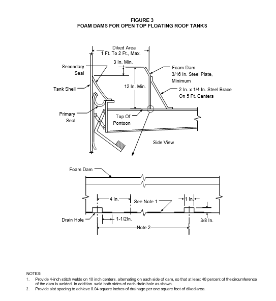
- Foam Dams
- (*)Unless specified by the Owner's Engineer, foam dams shall be provided on all open-top floating roof tanks over 100-foot diameter. As an alternative to foam dams, foam flow plates with burn out ports may be installed in the secondary seal support system for direct injection of foam between the primary and secondary seal, see EP 3-5-4.
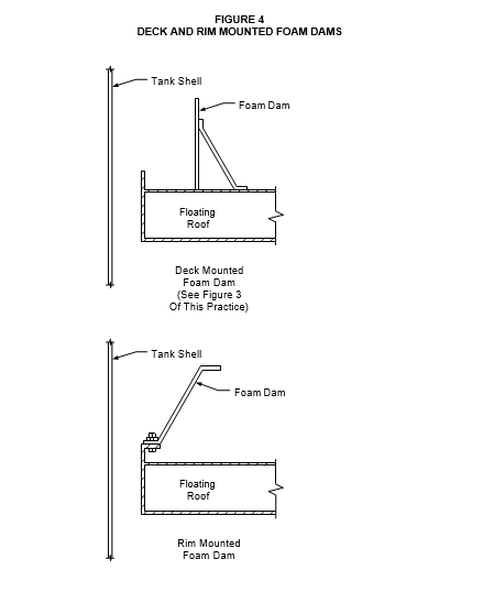
- Floating Roof, Deck-Mounted Foam Dam
- The dam should be 1 to 2 feet from the edge of the roof and should be a minimum of 12 inches high or 3 inches above the high point of the weather shield, secondary seal, any burn out panels in the metal secondary seal, or other mechanism.
- The dam shall be continuous, circular, and constructed from 3/16-inch steel plate (minimum), fillet welded with 4-inch stitch welds on 10-inch centers, alternating on each side of dam, so that at least 40 percent of the circumference of the dam is welded. Alternative means of securely fastening the foam dam to the roof may be presented to the Owner's Engineer for consideration.
- The dam should have periodically spaced rainwater drain slots with a total capacity for passing the maximum intensity rainfall. The drain slot size should be minimized to reduce the amount of foam lost during an emergency. Slots 3/8 inch high by 1 inch wide spaced at equal intervals to provide 0.04 square inches of area per one square foot of diked area will normally be adequate. There should be no other openings on the bottom of the dam.
- A typical foam-dam detail is shown in Figure 3.
- Floating Roof, Rim-Mounted Foam Dam
As an alternative to a floating roof foam dam deck mounted, a "bolt-on" rim mounted foam dam may be installed, see Figure 4. The foam dam shall be circular and constructed of 3/16- inch thick plate (minimum). The dam shall be 3 inches above the high point of the weather shield, secondary seal, any burn out panels in the metal secondary seal, or any other mechanism. Hot dipped galvanized plates shall be furnished unless stainless steel plates are specified. All metallic parts, including bars, plates, sheets, pins, bolts, nuts and wasters, etc. which are in contact with the stainless steel shoes shall be made of Type 300 Series stainless steel. Metallic parts not in contact with the stainless steel shoes shall be zinc or cadmium- plated carbon steel.
INTERNAL FLOATING ROOF SEAL SPECIFICATIONS
- Types of Seals
- (*)Welded Shells: Steel internal floating roofs in welded tanks with average annular spaces less than 7 inches and all aluminum internal floating roofs in welded shell tanks shall have a mechanical type "mini-shoe" seal or dual vapor-mounted wiper-type seals or toroidal foam filled seals as specified by the Owner's Engineer.
- Riveted Shells: Steel internal floating roofs in riveted tanks with an average annular space less than 4 inches and aluminum internal floating roofs in riveted tanks shall have a mechanical type "mini-shoe" seal or dual vapor-mounted wiper-type seals.
- Steel internal floating roofs in welded tanks with an average annular space greater than 7 inches or riveted tanks with an annular space greater than 4 inches shall have a standard stainless steel "mini-shoe" primary seal as described in Sections 7.0 and 8.0.
- Requirements for all Seal Designs
Seals around fixed roof support columns shall be designed to stay sealed continuously around the column throughout the maximum lateral movement allowed by the roof guide opening around the column. The seal design shall be adequate to prevent sagging of the seal throughout the life of the material. The Manufacturer shall submit his design with the bid proposal for review by the Owner's Engineer.
- Requirements for Mechanical "Mini-Shoe" Seals
Type 300 stainless steel 18-gage shoes shall be furnished. All bolts and clamping bars used to attach the main and expansion joint seal fabric to the stainless steel shoes and to attach the seal fabric to the roof rim shall be made of Type 300 Series stainless steel.
- Requirements for Wiper-type Seals
Wiper seals shall be wedge-shaped, microcellular, closed-cell. extruded urethane foam material that shall maintain the seal throughout a plus or minus 2-inch annular space variation. The material shall contain ultraviolet light and fungus inhibitors. The Manufacturer shall furnish any false rims, angles, brackets, etc., necessary to install the seals and make them fit and pass the local AQMD inspections and/or requirements.
- Requirements for Toroidal-type Seals
- Unless otherwise specified by the Owner's Engineer, toroidal-type seals are not to be used.
- If toroidal type seals are used, they shall meet the following requirements:
- The pressure that the seal exerts on the shell shall be uniform around the roof; it shall not greatly exceed that required to hold the seal in sliding contact with the tank shell and shall maintain sliding contact at all locations between the shell and seal.
- The seal assembly shall be designed and installed so that replacement of the fabric and foam can be performed while the tank is in service and without cutting or welding of the roof.
- A liquid-mounted (no vapor space) design shall be furnished.
- Design shall prevent roll-up of seal during tank pump down.
9.5.3 In the event an existing toroidal type seal leaks and must be removed from service, consideration must be given to the effort required to gas-free the tank in addition to the disposal requirements of product saturated foam and fabric material.
INSPECTION
- New Seal Installation
- (*)The Owner's Engineer and Manufacturer shall inspect the primary seal assembly first, then, if required, by the local AQMD inspectors to ensure its compliance with local rules and regulations. These inspections shall be performed after any repair to, or installation and/or replacement of, the primary seal assembly. The Manufacturer shall repair items found unacceptable during the inspections at Manufacturer's expense. The primary seal must pass the local AQMD inspection prior to installation of the secondary seal.
- (*)The Owner's Engineer and Manufacturer shall inspect the secondary seal assembly first, then, if required, by the local air district to ensure its compliance with local rules and regulations. These inspections shall be performed after any repair to, or installation and/or replacement of, the secondary seal assembly.
10.2 Existing Seal Installations
The inspection checklists in EP 9-1-3 C shall be used as a guideline in assessing the suitability of existing primary and secondary seals for continued service, or repair and/or replacement.
PROTECTION AGAINST IGNITIONS
- Fires have occurred when lightning has struck the rims of floating-roof tanks when the roofs were quite high and the contents volatile. Most of these fires have been above the seal and have been put out with hand foam lines or dry chemicals. Similar above-the-seal fires have occurred when direct lightning strikes to the rims of floating-roof tanks have ignited flammable vapors within the open shells.
- Fires have occurred in the seal space of open top, floating-roof tanks as a result of lightning that caused discharges. Ignition can be from the sudden discharge of an induced (bound) charge on the floating roof, released when the charge on a cloud discharges to ground somewhere in the vicinity of the tank.
- Metallic straps (shunts) at intervals of not over 10 feet on the circumference of the roof, between the floating roof and the metallic shoe that slides on the inside of the shell, will permit the charge to drain off without igniting vapor under the fabric seal. Tanks without a vapor space at the seal or with nonconductive seals do not generally require shunts at the seal. If shunts are omitted, a tight seal must be maintained to prevent the accumulation of vapors. Where metallic weather shields above the seal, wax scrapers or secondary seals are provided, they should maintain metallic contact with the shell. Secondary seals are subject to the same considerations as primary seals.
- All conductive parts of internal floating covers or the floating portions of covered floating-roof tanks should be electrically interconnected and bonded to the roof, shell, or bottom, see EP 13- 15-1.
12.0 TABLES
TABLE 1
GENERAL ELASTOMER CHEMICAL RESISTANCE CHART
| CHEMICAL | ELASTOMERS | ELASTOMERS | ELASTOMERS | ELASTOMERS | ELASTOMERS | METALS | METALS |
|---|---|---|---|---|---|---|---|
| URETHANE | NEOPRENE | BUNA-N | VlTON | TEFLON | GaIv(2) | Stainless | |
| 1-Butene | Note (4) | yes | Note (4) | yes | yes | yes | yes |
| 1-Butene, 2-Ethyl | Note (4) | yes | Note (4) | yes | yes | yes | yes |
| ASTM-Ref. #1 Oil | yes | yes | yes | yes | yes | yes | yes |
| ASTM-Ref: #2 Oil | yes | yes | yes | Note (4) | yes | yes | yes |
| ASTM-Ref: #3 Oil | yes | yes | yes | yes | yes | yes | yes |
| ASTM-Ref: Fuel A | yes | yes | yes | yes | yes | yes | yes |
| ASTM-Ref: Fuel B | yes | yes | yes | yes | yes | yes | yes |
| ASTM-Ref: Fuel C | yes | yes | Note (4) | yes | yes | yes | yes |
| Acetone | no | yes | no | no | yes | yes | yes |
| Alcohol - Absolute | no | yes | yes | yes | yes | yes | yes |
| Alcohol - Aliphatic | Note (4) | yes | yes | yes | yes | yes | yes |
| Alcohol - Aromatic | Note (4) | yes (1) | yes (1) | yes | yes | yes | yes |
| Alcohol - Denatured | no | yes | yes | yes | yes | yes | yes |
| Alcohol - Ether | Note (4) | yes (1) | yes (1) | yes | yes | yes | yes |
| Alcohol - Ethyl | no | yes | yes | yes | yes | yes | yes |
| Alcohol - Grain | no | yes | yes | yes | yes | yes | yes |
| Alcohol - Methyl | no | yes | yes | yes (1) | yes | yes | yes |
| Allyl Alcohol | Note (4) | yes | yes | yes | yes | yes | yes |
| Aminohexane | Note (4) | Note (4) | yes (1) | no | yes | yes | yes |
| Aminopentane | Note (4) | no | yes (1) | no | yes | yes | yes |
| Aminoxylene | Note (4) | no | no | yes (1) | yes | yes | yes |
| Aromatic Hydrocarbons | yes (1) | no | yes (1) | yes | yes | yes | yes |
| Aromatic Spirits | Note (4) | Note (4) | yes (1) | yes | yes | yes | yes |
| Aromatic Tar | Note (4) | Note (4) | yes (1) | yes | yes | yes | yes |
| Asphalt | yes | yes | yes | yes | yes | yes | yes |
| Astral Oil | yes (1) | yes | yes | yes | yes | yes | yes |
| Aviation Gasoline | yes (1) | yes (1) | yes | yes | yes | yes | yes |
| Benzene | no | no | yes (1) | yes | yes | yes | yes |
| Benzene | Note (4) | yes | yes | yes | yes | yes | yes |
| Benzene Solvent | Note (4) | yes | yes | yes | yes | yes | yes |
| Black Liquor | Note (4) | yes | yes | yes | yes | yes | yes |
| Black Liquor - Waste | Note (4) | yes | yes | yes | yes | yes | yes |
| CHEMICAL | ELASTOMERS | ELASTOMERS | ELASTOMERS | ELASTOMERS | ELASTOMERS | METALS | METALS |
|---|---|---|---|---|---|---|---|
| URETHANE | NEOPRENE | BUNA-N | VlTON | TEFLON | GaIv(2) | Stainless | |
| Boiled Linseed Oil | yes | yes | yes | yes | yes | yes | yes |
| Butane | yes | yes | yes | yes | yes | yes | yes |
| Butanol | no | yes | yes | yes | yes | yes | yes |
| Butozyethanol | Note (4) | yes (1) | yes | yes (1) | yes | yes | yes |
| Crude Oil (Sour) | yes | yes (1) | yes | yes | yes | no | yes (3) |
| Crude Oil (Sweet) | yes | yes (1) | yes | yes | yes | no | yes |
| Diesel Oil | yes | yes | yes | yes | yes | yes | yes |
| Gasoline | yes | yes | yes | yes | yes | yes | yes |
| Jet Fuels (JP1-JP6, A & A1) | yes | yes | yes | yes | yes | no | yes |
| MTBE | no | no | yes (1) | no | yes | yes | yes |
| Methanol | no | yes | yes | yes (1) | yes | yes | yes |
| Naphtha | no | no | yes | yes | yes | yes | yes |
| Toluene | yes (1) | no | yes (1) | yes | yes | yes | yes |
NOTES:
- Reduced service life can be expected when this elastomer is exposed to certain types, grades or concentrations of this product (chemical). Actual service life depends on the proximity of the elastomer to the product. Materials in direct contact with liquid or exposed to concentrated vapors will have a shorter life than materials exposed to air containing varying amounts of the product vapors.
- Reduced service life can be expected if the stored product contains caustics or hydrogen sulfides. Use of stainless steel metal components is strongly recommended if this situation exists.
- Certain grades of crude oil that contain high concentrations of H2S may require the use of Type 316 stainless steel components.
- Insufficient data available.
- The above guidelines were compiled from data believed to be accurate. However, due to unique environmental conditions and contamination, these recommendations are guides only. Sour tanks with HS levels in excess of 300 parts per million should be evaluated separately.
TABLE 2
RECOMMENDED TECHNICAL PROPERTIES FOR ELASTOMERS
| PROPERTY | TEST METHOD | TYPICAL VALVE |
|---|---|---|
| Low Temperature | 1/8" mandrel | -45° F (No Crack) |
| Permeability | ASTM D814 | Less than 0.05 oz. per ft2 per 24 hours in the test fuel (1) |
| Volume Swell | ASTM D543 | Less than 2% after 24 hours immersion in the test fuel (1) |
| Elongation | ASTM D751 | Less than 5% after 24 hours immersion in the test fuel (1) |
| Hardness | ASTM D2240 | Shore A hardness after 24 hours of immersion in the test fuel (1) is within 5% of original hardness. |
| Solubility | Rate of solubility in the test fuel (1) for a period of 24 hrs. does not exceed 0.1 percent by weight. |
NOTES:
(1) The test fuel is 30% toluene and 70% iso-octane and simulates testing with gasoline, diesel fuel, jet-fuel, kerosene and gasohol.
© 2026 Inflection Point Engineering, LLC. All rights reserved. The content of this page — including calculation methods, reference data, written analysis, interactive tools, and source code — is the intellectual property of Inflection Point Engineering, LLC and is protected under applicable copyright, trademark, and trade secret laws. Unauthorized reproduction, redistribution, modification, or derivative use in whole or in part is prohibited without prior written consent.
Disclaimer. This material is provided for informational and educational purposes only and does not constitute professional engineering advice. Calculations, reference data, and methodologies are based on published standards and accepted engineering practice but are not a substitute for engineering judgment, site-specific analysis, or review by a licensed Professional Engineer. Inflection Point Engineering, LLC makes no warranties, express or implied, regarding the accuracy, completeness, or fitness for a particular purpose of any content presented here, and shall not be liable for any direct, indirect, incidental, or consequential damages arising from its use. Users assume all risk associated with applying this content to real-world design, operations, or decisions.
© 2026 Inflection Point Engineering, LLC. All rights reserved.