 Section 9 — Storage Tanks
Atmospheric Storage Tanks
IPE Engineering Practice IPE-EP-9-1-1
Document number: IPE-EP-9-1-1 · Section: 9 — Storage Tanks

SCOPE
- This Practice covers mandatory requirements governing the design, fabrication, erection, inspection and testing of new welded steel tanks for aboveground atmospheric storage. Tanks within the scope of API 650 Appendix A or Appendix J are also covered in this Practice. The requirements given herein supplement and modify those of API Standard 650.
- Supplemental requirements including the data to be furnished by the Purchaser, the Manufacturer’s responsibility, documentation, and marking, packaging and shipping are covered in EP 9–3–1.
- Requirements for accessories for atmospheric storage tanks are covered in EP 9–1–4.
- Any deviation to this Practice must be approved by the procedure described in EP 1–1–3.
- An asterisk (*) indicates that a decision by the Owner or Owner’s Engineer is required, or that additional information is furnished by the Purchaser.
- A revision bar indicates all changes made to this Revision.
2.0 REFERENCES
The latest edition of the following standards and publications are referred to herein.
STANDARDS AND PUBLICATIONS
STANDARDS AND PUBLICATIONS (CONT.)
| API Standards |
|---|
| Std 650 Welded Steel Tanks for Oil Storage Std 653 Tank Inspection Repair, Alternation, and Reconstruction Std 2000 Venting Atmospheric and Low Pressure Storage Tanks Std 2350 Overfill Protection for Petroleum Storage Tanks Std 5L Specification Standard for Line Pipe |
| ASTM Standards |
| A36 Structural Steel A105 Carbon Steel Forgings for Piping Components A106 Seamless Carbon steel Pipe for High–Temperature Service A131 Structural Steel for Ships A181 Carbon Steel Forgings for General Purpose Piping A283 Low and Intermediate Tensile Strength Carbon Steel Plates, Shapes, and Bars A285 Pressure Vessel Plates, Carbon Steel, Low and Intermediate Tensile Strength A307 Carbon Steel Bolts and Studs, 60,000 psi Tensile Strength A333 Seamless and Welded Steel Pipe for Low–Temperature Service A334 Seamless and Welded Carbon and Alloy Steel tubes for Low Temperature Service A350 Carbon and Low–Alloy Steel Forgings Requiring Notch Toughness Testing for Piping Components A442 Pressure Vessel Plates, Carbon Steel, Improved Transition Properties A516 Pressure Vessel Plates, Carbon Steel, for Moderate– and Lower–Temperature Service A524 Seamless Carbon Steel Pipe for Atmospheric and Lower Temperatures A570 Hot– Rolled Carbon Steel Sheet and Strip, Structural Quality A573 Structural Carbon Steel Plates of Improved Toughness A633 Normalized High–Strength, Low–Alloy Structural Steel A671 Electric–Fusion–Welded Steel Pipe for Atmospheric and Lower Temperatures |
| ANSI Standard |
| B16.11 Forged Steel Fittings, Socket–Welding and Threaded |
DEFINITIONS
- Aggressive Environmental Service (AES) - Process services which result in material degradation such as cracking, scaling, blistering, and severe pitting and/or corrosion. Examples of such services are hydrogen service, wet hydrogen sulfide, cyanides, caustic, amine, and hydrofluoric acid. AES process fluid are defined in EP 10–2–1.
- Contractor - Company or business that agrees to furnish materials or perform specified services at a specified price and/or rate to the Owner.
- Fully Stiffened Pontoons - Floating roof pontoons having top and bottom plates reinforced such that the entire pontoon cross section is effective in carrying transmitted loads from the center deck.
- Inspector - A Inflection Point Engineering, LLC Engineering Company appointed engineer or inspector.
- Manufacturer - The recipient of a direct or indirect purchase order for materials and/or equipment. In this context, a direct order is one issued to a manufacturer by a contractor or the Owner. An indirect order is one issued to a manufacturer by a vendor (recipient of a direct order) for materials, fabricated components, or subassemblies.
- Owner - Inflection Point Engineering, LLC Engineering Company.
- Owner’s Engineer - A Inflection Point Engineering, LLC Engineering Company appointed engineer.
- Partially Stiffened Pontoon - Floating roof pontoons having top and bottom plates reinforced such that only part of the pontoon cross section is effective in carrying transmitted loads from the center deck.
- Purchase Order - The contractual document given to the Manufacturer to authorize a purchase.
- Purchaser - The party placing a direct purchase order. The purchaser is the Owner’s designated representative.
DATA SHEET AND DOCUMENTATION
- (*)The Atmospheric Storage Tank Data Sheet given in EP 9–1–1 DS shall be completed along with a line drawing by the Owner’s Engineer showing the tank design data, dimensions, schedule of openings, notes and all other requirements necessary to prepare the design and fabrication drawings. The Manufacturer shall use this information to supply with his quotation a completed Atmospheric Storage Tank Data Sheet containing all the relevant information necessary for appraisal of the mechanical design by the Purchaser. Also included shall be any additional drawings and specifications, and a list of any proposed subcontractors.
- Upon completion of tank fabrication, the Manufacturer shall furnish the Owner’s Engineer with a copy of the applicable Atmospheric Storage Tank Data Sheet corrected to reflect the as–built conditions.
- Additional documentation requirements for API 650 tanks are stipulated in EP 9–3–1.
5.0 QUALITY CONTROL
The Manufacturer shall have, as part of his usual business practice, an established quality control system. In addition, a quality control plan shall be developed for the manufacture of a new atmospheric storage tank to ensure that all technical requirements are followed.
Requirements for this quality control system and plan are covered in EP 9–3–1.
MATERIALS
- Permissible materials of construction for tank components are listed in Table 1. The final selection of a material shall be based on the requirements stipulated in paragraph 6.3.
- Annular plates shall be of the same material specification and grade, and have the same impact properties as the lowest shell course material.
- The final selection of materials for tank construction shall be based on the toughness requirements of API 650. The minimum permissible design metal temperature to be used in material selection shall be based on Table 2.
- When impact testing is required, it shall be performed in accordance with API 650.
- When the design utilizes normalized plate, the Manufacturer shall not destroy the normalized properties of the plate during fabrication.
- Materials for gaskets and bolting shall be in accordance with EP 5–2–2. Spiral wound gaskets shall be used with all nozzle connections, and sheet gaskets shall be used with manhole connections.
- (*)Additional requirements for materials, welding control, Brinell hardness and heat treatment will be specified by the Owner’s Engineer for tanks in AES, see EP 10–2–1 and EP 10–2–3.
- Cast fittings or other components shall not be used in the tank shell or bottom
- (*)When specified by the Owner’s Engineer, protective coatings and materials for corrosion protection shall be as follows:
- Gage wells, floating–roof guide poles, floating–roof support legs and sleeves, deck vents and sleeves, roof drain piping, and emergency drains shall be hot–dipped galvanized after fabrication and welding (except for attachment weld to tank).
- Roof support legs shall be equipped with stainless steel support pins and cotter pins.
- (*)Floating cover materials and joint–sealing compounds (if used) shall be suitable for the product stored and exposure. The following shall be specified by the Owner’s Engineer:
- Ambient and design temperatures.
- Product stored.
- Corrosive media present in the product stored.
DESIGN
General
(*)The design, fabrication, and erection of storage tanks and their appurtenances shall be in accordance with API 650, the requirements of this Practice, and the requirements of all governmental agencies having jurisdiction in the area where the tanks are to be erected and used. When conflicts between these requirements occur, the most stringent requirements, as determined by the Owner’s Engineer, shall govern.
Joints
- All vertical and horizontal shell joints shall be full–penetration and full–fusion welds. Single–pass butt welds shall not be permitted. Vertical joints in adjacent shell courses shall be offset from each other a minimum of 12 inches.
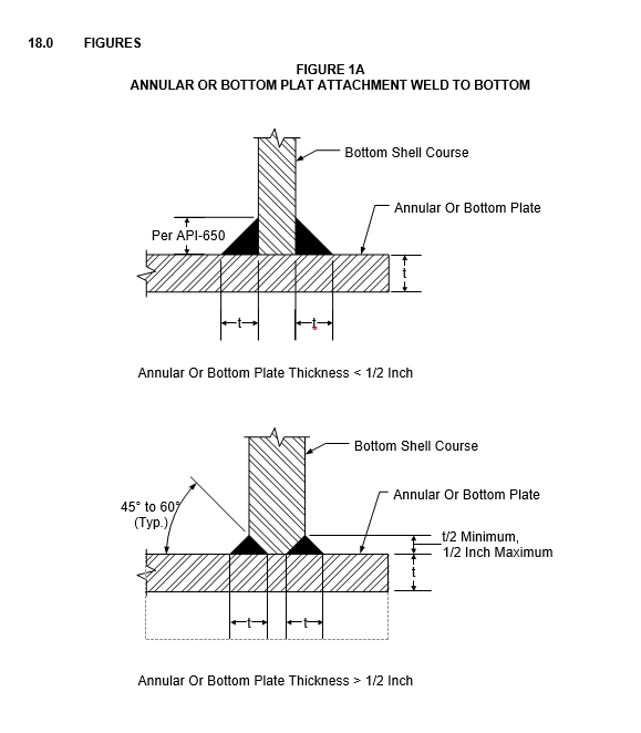
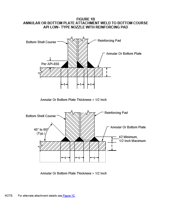
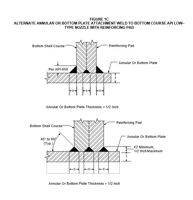
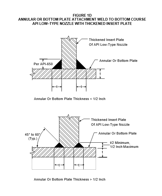
- The shell bottom course to annular or bottom plate weld shall be in accordance with Figure 1A, Figure1B, Figure1C, and Figure 1D. This weld shall be made with a minimum of two layers.
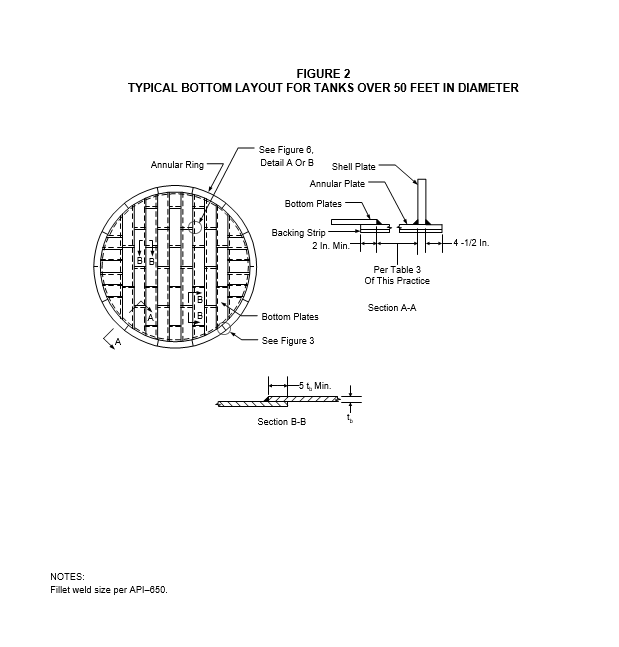
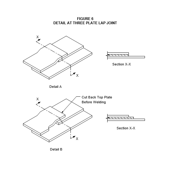
- Weld joint design for tanks with bottom annular plates shall be in accordance with Figure 2, Figure 3 and Figure 6.
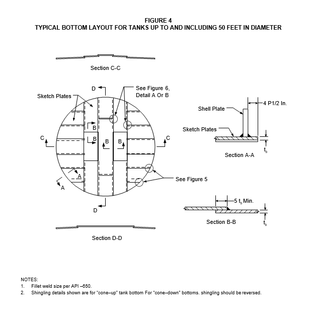
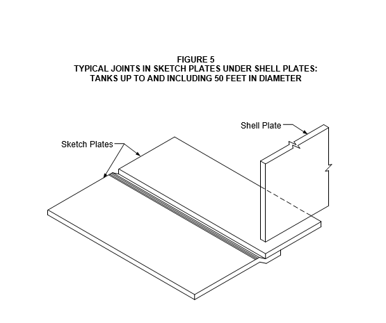
- Weld joint design for tanks with bottom sketch plates shall be in accordance with Figure 4, Figure 5 and Figure 6.
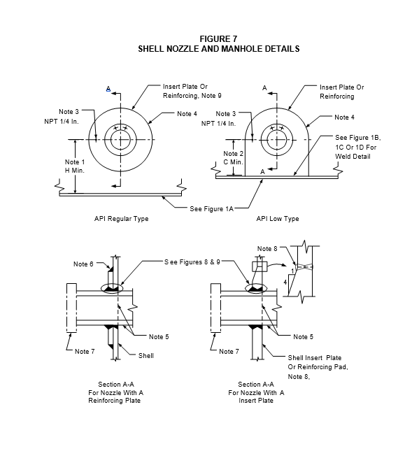
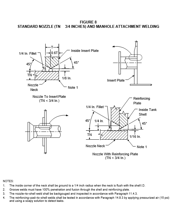
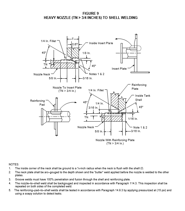
- Weld joint design for shell nozzles and manways shall be in accordance with Figure 7, Figure 8 and Figure 9.
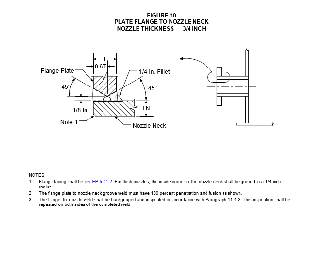
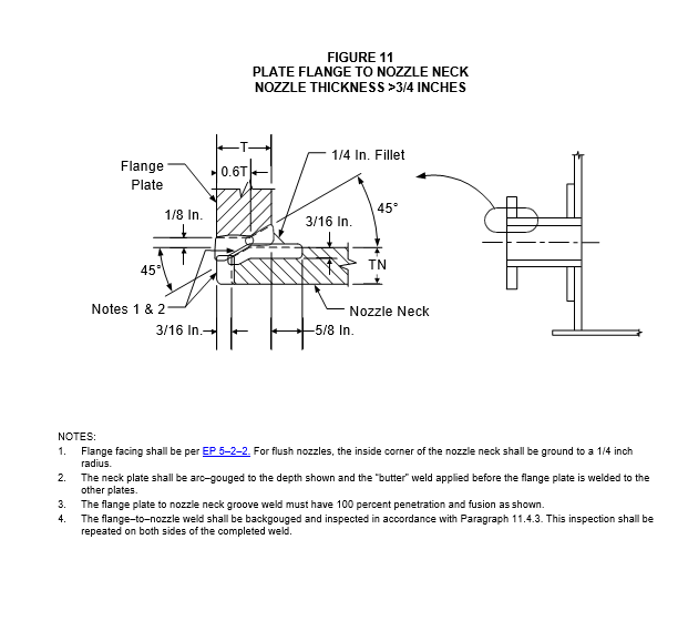
- Weld joint design for the attachment of plate flanges to nozzles shall be in accordance with Figure 10 and Figure 11.
- Weld joint design for tank bottom plates shall be in accordance with Table 3 and paragraph 7.4.
- Pressure piping welds located inside the tank, such as welds on steam coils, shall be full penetration welds.
Design and Special Considerations
- Requirements for foundation design for new tank construction shall be in accordance with EP 4–2–7.
- (*)Unless otherwise specified by the Owner’s Engineer, the minimum corrosion allowance to be applied to all wetted surfaces of the tank (shell, bottom and structural members in contact with the stored product) which are not coated with a corrosion resistant lining shall be 1/16 of an inch. The corrosion allowance for un–wetted surfaces (e.g. the underside of a cone roof, both roof plates and structurals) will be specified by the Owner’s Engineer.
- Tanks in AES shall meet all requirements specified in EP 10–2–1.
Bottom and Annular Plates
- (*)Tank bottoms shall be specified by the Owner’s Engineer as sloped “cone–up” or “cone– down”. Flat bottoms are acceptable only for small diameter, shop–fabricated tanks built in accordance with Appendix J of API 650. All bottom plate joints in the finished tank floor shall be “shingled” to facilitate drainage toward the tank shell for “cone–up” tank bottoms and toward the center sump for “cone–down” tank bottoms. The slope of the tank floor shall in accordance with EP 4–2–7 unless otherwise specified by the Owner’s Engineer.
- The minimum thickness of the tank bottom plates shall be 1/4 inch plus the specified corrosion allowance in paragraph 7.3.2.
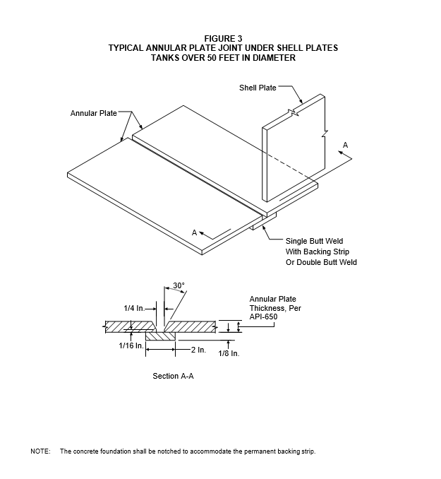
- All tanks with a diameter greater than 50 feet shall have a ring of annular plates underneath the tank shell, see Figure 2 and Figure 3. Bottoms for tanks up to and including 50 feet in diameter shall be constructed with annular rings or from rectangular plates, with sketch plates to the perimeter, see Figure 4 and Figure 5.
- (*)The “category of bottom” required for a tank design shall be specified by the Owner’s Engineer. The categories, specific design, and construction features for each category are stipulated in Table 3.
- Annular plates shall meet the following criteria:
- The annular plate thickness shall be per API 650.
- Annular plates shall extend at least 4±1/2 inches outside the tank shell.
- Annular bottom plates shall be butt-welded with complete penetration and fusion, see Figure 2 and Figure 3.
Shell Design
- The tank shell course thickness, for tanks with a diameter of 200 feet or greater, shall be designed using the Variable Design Point Method of API 650. For tanks less than 200 ft, either the 1–Foot Method or the Variable Point Method shall be used. For either method the following shall be used:
- Specific Gravity, G: use the value specified on the Atmospheric Storage Tank Data Sheet.
- Corrosion Allowance, CA: use the value specified on the Atmospheric Storage Tank Data Sheet.
- Maximum Allowable Stress, S: In accordance with API 650, Table 3–2.
- For tanks designed per Appendix A of API–650, the joint efficiency factor shall be 0.85, and spot radiography shall be per paragraph 11.2.
- The minimum tank shell course thickness, including the corrosion allowance, shall be as stipulated in Table 4. In no case shall the thickness provided in any course be less than that of the course above.
- For fixed roof tanks, the height specified shall be from the bottom of the shell to the top of the top angle. Where an internal roof or floating cover will be used, the design shall take into account the dimensions of the internal roof or cover to provide the full shell height specified.
- For floating roof tanks, the height specified shall be from the bottom of the shell to the maximum filling height. A shell extension of a sufficient height shall be provided, as required to accommodate the roof above the specified height, and shall be designed such that no damage will occur to the roof seal if the tank is overfilled.
- Where the tank capacity is specified, this shall be taken as the usable tank volume. For tanks with floating roofs or internal floating covers, the usable volume shall be determined with the roof at its maximum recommended operating level.
Shell Openings (Nozzles and Manways)
- (*)Nozzles for process connections shall be specified by the Owner’s Engineer. Requirements for manways, instrument connections, and vents are covered in this section and EP 9–1–4.
- All connections shall be flanged using a minimum nozzle size of NPS 1. Nozzle sizes of NPS 1– 1/4, 2–1/4, 3–1/2, and 5 shall not be used.
- (*)Flanged nozzles shall be specified as API Regular Type or Low Type, see Figure 7. API Flush Type nozzles shall not be used unless otherwise specified by the Owner’s Engineer.
- (*)Nozzles for internal tank piping connections shall extend into the tank per API 650. The internal end of the nozzle shall be supplied with a flanged connection unless otherwise specified by the Owners Engineer.
- (*)Unless otherwise specified by the Owner’s Engineer, flanges for shell connections shall be as follows:
- Shell nozzles and manholes shall have ASME/ANSI Class 150, slip–on or weld neck flanges per EP 5–2–2, unless otherwise permitted in the following paragraph.
- In lieu of forged steel flanges, shell manholes may be supplied with plate ring flanges provided that both the bolting flange and its cover plate are designed as mixer manhole components in accordance with API 650. The finished thickness of the bolting flange and its cover plate shall be equal. Welding of the plate ring to nozzle neck shall be in accordance with the details shown in Figure 10 and Figure 11.
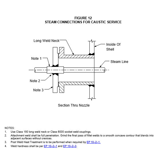
- Steam and condensate nozzles for caustic service tanks shall be in accordance with Figure 12.
- Mixer nozzles shall be installed in the cover plate of a mixer manhole sized to permit complete withdrawal of the mixer and its impeller without the need for access to the inside of the tank. Supports for the mixer shall be designed to ensure that the mixer and tank move together as the tank settles.
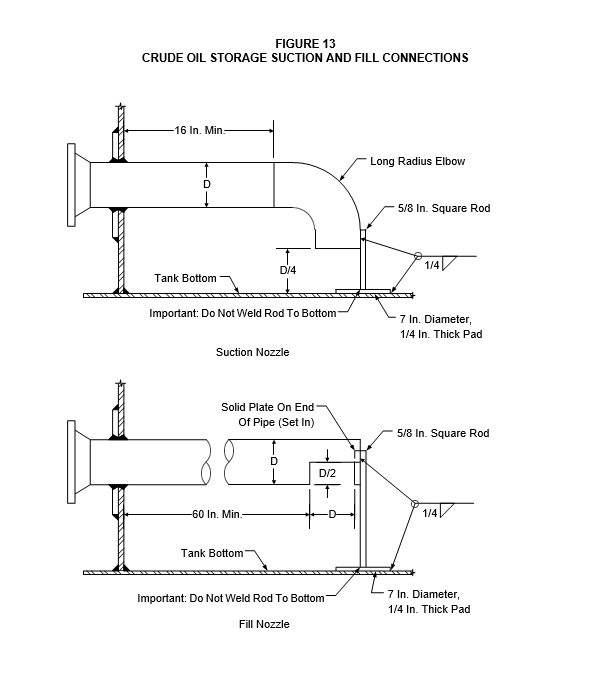
- (*)Unless otherwise specified by the Owner’s Engineer, suction and fill nozzles in crude oil storage tanks shall be in accordance with Figure 13.
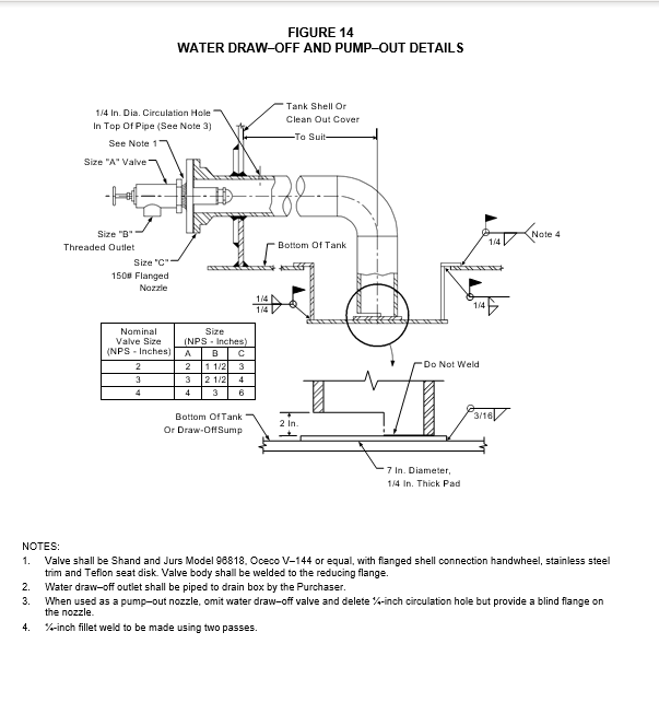
- (*)Unless otherwise specified by the Owner’s Engineer, water draw–off and pump–out connections shall be in accordance with Figure 14. Alternative details shall be considered for tanks where excessive differential settlement between the nozzle to shell and nozzle to tank bottom connections is anticipated.
- The allowable external loads on all tank shell openings shall be checked using the procedures of API 650, Appendix P. The piping stress analysis used to determine the nozzle reactions shall be in accordance with EP 5–1–3.
- (*)Unless otherwise specified by the Owner’s Engineer, the minimum number and size of shell manholes shall be in accordance with Table 5. The manholes shall be equally spaced around the tank.
- Shell manholes for floating roof tanks, which do not have metallic seals, shall be provided with filler pieces flush with the inside of the shell and attached to the manhole cover.
Shell Attachments and Roof Appurtenances
- The edge of permanent shell attachment welds for clips, lugs, etc., shall be located at least 3 inches from shell horizontal seams and at least 6 inches from shell vertical seams.
- The wall thicknesses of roof nozzles are shown in Table 6.
- Gage hatches shall be NPS 8, spark–resistant and self–closing. The gage hatch shall be fillet– welded to the nozzle on an uninsulated roof, and bolted to a roof nozzle on an insulated roof. Hatches shall remain closed during the normal operating cycle of the tank pressure vacuum relief vent(s).
- (*)Unless otherwise specified by the Owner’s Engineer, roof manholes shall be provided as shown in Table 7.
- If the tank has an automatic tank gage, then one roof manhole or an inspection hatch shall be placed immediately adjacent to its roof connections.
- A scaffold cable support shall be provided on all fixed-roof vertical tanks over 18 feet in height. Its design shall be as shown in API 650. The roof vent may serve as the scaffold cable support provided it is at least as large and has the same type of reinforcement and attachment details as the scaffold cable support shown in API 650.
- NPS 1 nozzles shall be welded to the roofs of fixed roof tanks for the installation of tank gage spring housings or similar threaded connections. Pipe nipples shall not be welded to tank roofs.
Top and Intermediate Wind Girders
- Top and intermediate wind girders for open roof tanks, and intermediate wind girders for fixed roof tanks shall be designed in accordance with the procedures of API 650. The design of the top and intermediate wind girders shall be based on the corroded tank shell thickness.
- (*)The design wind speed shall be 100 mph unless otherwise specified by the Owner’s Engineer.
- Wind girders specified to be used as walkways shall be a minimum of 30 inches wide and shall be located 3 feet 6 inches below the top of the tank unless an inside handrail (which will not interfere with the floating roof) is provided per EP 9–1–4.
- Where a curb angle is required at the top of the shell of floating roof tanks, the horizontal leg shall extend outward.
- The butt welds joining wind-girder or wind-stiffener sections shall be at least 6 inches away from shell vertical seams. A “rat–hole” shall be provided at the ends of wind-girder and wind-stiffener sections to prevent contact between the stiffener butt weld and the shell.
- The attachment weld for wind-girders and wind-stiffeners shall be at least 3 inches away from any horizontal shell seam.
- Sufficient drain holes shall be provided in wind girders to prevent water accumulation and subsequent corrosion of the shell and girder.
Fixed Roofs
- A top angle shall be provided for all fixed roof tanks.
- The top angle–to–shell joint shall be butt–welded with complete penetration and complete fusion. The top angle horizontal leg shall be turned outward.
- (*)One half (180 degrees) of the fillet weld joining a cone roof to the top angle shall be a 1/8- inch weak seam The other 180 degrees of weld shall be in accordance with API 650. The 1/8- inch weak seam shall be on the opposite side of the tank from the top of the stairway or ladder. The weak seam shall also be located taking into consideration adjacent tanks, process units and/or property lines and right-of-ways. The location of the weak seam with respect to plant “north” shall be indicated on tank drawings and shall be subject to Owner’s Engineer approval.
- When a self–supporting dome or umbrella roof design is specified or when design of a frangible roof is not possible, emergency venting per API 2000 shall be provided, see EP 9–1–4.
- Bearing plates shall be provided for roof support columns. Plates shall be 3/8-inch thick and 24 inches round or octagonal. They shall be continuously welded to the tank floor with a 1/4 inch fillet.
- The roof lap joints shall be shingled so that drainage will occur toward the tank shell. The minimum overlap between roof plates shall be six times the roof plate thickness or 2 inches, whichever is greater.
- Support columns for fixed–roofed tanks that have internal floating roofs shall be pipe sections.
Wind Loads on Tanks (Overturning Stability)
- (*)The Manufacturer shall compute the wind overturning stability for all tanks per API 650 to determine the need for anchor bolts. The calculation shall be submitted for review and approval by the Owner’s Engineer.
- Anchor bolts shall be provided when required to resist overturning or uplift due to internal pressure, wind or seismic forces. In such cases, anchor bolts shall meet the following:
- Anchor bolts shall not be less than 1–1/4 inch diameter.
- Attachment of anchor bolts to the shell shall be through chair–type assemblies of sufficient size to distribute the load over a reasonable area of the shell. Chair height shall be at least 12 inches.
EXTERNAL FLOATING ROOF DESIGN
General
- All floating roofs shall be designed, fabricated, inspected, and tested in accordance with API 650, Appendix C and the additional requirements of this Practice.
- Materials for floating roof components shall be per Section 6.0.
- (*)Unless otherwise specified by the Owner’s Engineer, single deck, annular pontoon roofs greater than 60 feet in diameter shall be per the following:
- All roofs shall be of the low deck (minimum vapor space) type.
- Center decks greater than 150 feet in diameter shall have channel stiffeners on the underside of the deck Stiffeners shall be 6 inch x 8.2 pound American Standard channel or equivalent, and be installed as concentric rings with a maximum radial spacing of 20 ft.
- Roofs for tanks greater than 200 feet in diameter shall be designed for elastic stability against global out–of–plane buckling and local buckling of the outer pontoon due to the radial load imposed by deflection of the center–deck. This radial load shall be determined from the 10-inch design rainfall load as defined in API 650, Appendix C, or the punctured center–deck loading condition, whichever governs. For prevention of global out–of–plane buckling, the following relationships shall be satisfied:
N CEI / R 3
Where, C 7.5 for fully stiffened pontoons, 5.0 for partially stiffened pontoons N Design radial inward load, lb./in.
E Modulus of elasticity, psi
R Mean radius of pontoon ring, in
I Moment of inertia of the full cross - section of the outer pontoon with respect to the horizontal axis through its centroid, in4
- The inner and outer rims of partially and fully stiffened pontoons shall have a minimum thickness as shown in Table 8.
- The radial unsupported width of Partially Stiffened plates shall not exceed 10 feet.
- For tanks greater than 200 feet in diameter, calculations and tests required to substantiate the elastic stability of the root pontoon design shall be as follows:
- (*)Where roof designs have not been previously approved by the Owner’s Engineer, the Manufacturer shall submit test data on a roof of similar diameter to validate the design.
- Where validation has not been made, the Manufacturer shall conduct a proof test on the largest tank supplied on the order. The proof test shall be based on the most critical design loading conditions.
- (*)Calculations shall be submitted to Purchaser for approval by the Owner’s Engineer.
- Roofs greater than 300 feet diameter shall have the following construction:
- The roof shall be of the double–deck type.
- The top edge of inner rim plates in the first two central compartments shall be welded with continuous single fillet welds.
- All internal bulkhead plates and sheets shall be continuously one pass fillet welded along the top, bottom and vertical sides to assure liquid tightness.
- The minimum size for pontoon compartment manways shall be 24 inches.
Support Legs
- Supports shall be the same material as the tank roof, NPS 4 inch schedule 80 minimum thickness. The radial clearance between the support and the roof support sleeve shall be 1/8 inch.
- Supports shall be adjustable to a minimum of two positions:
- The lower position shall permit the roof to go 3 inches below the specified lowest operating position without interference with any internal accessories or roof seal mechanism.
- The upper position (for cleaning) shall provide for a minimum clearance of 7 feet between the lowest portion of the roof and the tank bottom.
- When specified by the Owner’s Engineer, additional holes between these positions (typical 6 inch spacing) shall be included to account for uneven settlement.
- Bearing plates shall be centered under each support, attached to the bottom by a ¼-inch continuous fillet weld. Plates shall be 3/8-inch thick and 24 inch round or octagonal, and shall be the same material as the tank bottom.
- (*)The length of the leg support sleeves shall be such that any opening will be above the liquid level when the deck is deflected by the 10-inch design rainfall or in the punctured center deck design condition. Unless otherwise specified by the Owner’s Engineer, in no case shall the height of the support sleeves for single–deck pontoon roofs be less than the tank diameter divided by 60.
- Support legs shall be notched at the bottom to provide drainage.
Seals and Foam Dams
Seals and foam dams for external floating roof tanks shall be in accordance with EP 9–1–3.
Roof Drains
- (*)Primary roof drains shall be armor clad hose (e.g., Coflexip or equal as determined by the Owner’s Engineer) equipped with symmetrical swivel joints, unless articulated pipe drains are specified by Owner’s Engineer. The inlet for these drains shall have a swing type check valve to prevent product from flowing onto the roof if the drain fails.
- (*)The quantity and size of primary roof drains shall be determined in accordance with API 650, Appendix C. The maximum rainfall rate for sizing of roofs drains shall be specified by the Owner’s Engineer.
- Hose drains shall be of a repeatable lay pattern type with a metal casing inside or outside. No part of a hose drain shall be closer than two feet to a roof support leg, steam coil or other potential obstruction at any point in the roof’s travel unless hose guards are provided.
- Shell connections for roof drains shall be fitted with flanged steel valves.
- (*)Unless otherwise specified by the Owner’s Engineer, the roof drain design and locations shall not prevent the bottom of the roof from being lowered to a point 30 inches above the tank shell bottom.
- (*)When specified by the Owner’s Engineer, all roof drains must be designed to withstand freezing of water inside the drain without any damage being incurred as a result of freeze/thaw cycles.
- Out–of–service drain plugs shall be provided in the top of each floating roof deck.
- Emergency drains shall also be provided in areas where the rainfall is expected to exceed 10 inches in a 24–hour period. Emergency drains shall be of open–type design, and as follows:
- (*)Emergency drains are required for double–deck roofs. The quantity of water to be handled shall be specified by Owner’s Engineer.
- Emergency drains shall not be provided for pontoon–type roofs if the pontoon area is less than 50 percent of the total projected roof area.
- For double–deck–type roofs only, credit may be taken in the roof design for any emergency drains provided.
- Height of emergency drains shall be determined by roof deflection under specified rain loading.
- Roof drains are not acceptable unless tested under service–like conditions by an independent testing facility. The test results shall include the following data:
- The total number of cycles required for leakage and/or mechanical failure under ambient conditions.
- Performance under freeze conditions, if applicable, the drain is to be filled with water, refrigerated until the water is frozen solid and then flexed or cycled to its design limit of travel several times until all stiffness due to ice has been overcome or until the drain fails.
Roof Vents
- (*)Each roof shall be equipped with a bleeder vent designed to open automatically when the roof lowers to its lowest operating position or lower leg setting, and to close automatically when the roof rises above either of these positions. Unless otherwise specified by the Owner’s Engineer, the bleeder vent shall be designed to open and close within 12 inches of these positions. The vent or vents shall be sized to prevent creation of vacuum or pressure below the roof at maximum fill or pump–out rates.
- When flexible steel shoe–type seals are employed, the roof shall be equipped with a rim vent(s). This vent(s) shall release excess air or non-condensable vapors in the tank seal area.
INTERNAL FLOATING ROOF DESIGN
General
- All internal floating roofs shall be designed, fabricated, inspected, and tested in accordance with API 650, Appendix H and the additional requirements of this Practice.
- The internal floating roof and accessories shall be so designed and constructed as to allow the tank to overflow and then return to a liquid level which floats the cover well below the top of the tank shell without damage to any part of the cover, tank or appurtenances. During such an occurrence, no manual attention shall be required to protect the cover, tank, or appurtenances.
- Internal floating roof designs that employ pontoons for flotation shall have at least 100% excess pontoon volume for buoyancy.
- The minimum volume of a single deck pontoon, pipe pontoon, or double deck design shall be sufficient to keep the roof floating on a liquid with a specific gravity of 0.7 if any two compartments are punctured.
- The internal floating roofs shall be designed to support a 500 lb. minimum point load over its entire surface, during operation and while resting on the support legs, to provide personnel access to all cover appurtenances, to all support legs, and to the peripheral seal. The design shall not allow contents to flow onto the roof when this load is imposed. The roof shall be designed and constructed to float in a flat position (no slope). Foam materials shall not be used to achieve flotation.
- (*)Non–metallic internal floating roofs require approval by the Owner’s Engineer. However, such designs are not acceptable for tank diameters greater than 60 feet.
- All seams in the internal floating roof shall be vapor tight.
- For internal floating roofs that do not fully contact the liquid, there shall be a skirt (vapor seal) around the roof periphery extending into the liquid a minimum of 6 inches. In addition, all openings through the roof shall have a skirt extending into the liquid a minimum of 6 inches.
- The periphery and all penetrations in steel internal floating roofs shall have a rim plate that extends at least 8 inches above the roof.
- All internal bulkheads in the compartments of steel pontoon and double deck designs shall have a continuous fillet weld along the bottom, top and vertical edges.
Internal Floating Roof Appurtenances
- An anti–rotation device shall be provided for all internal floating roofs. Anti–rotational devices shall be provided to maintain the roof in a centered position and to prevent its rotation.
- (*)Unless otherwise specified by the Owner’s Engineer, the number and size of manholes in the internal floating roof shall be as shown in Table 9.
- (*)Access to internal floating roofs shall be provided by a ladder if specified by the Owner’s Engineer. If a permanent ladder is not specified, a pad shall be provided on the roof equipped with cleats that will accommodate and prevent slippage of a ladder (temporary) placed on it. The pad shall be located in direct vertical alignment with the roof access manway. If a permanent ladder is specified, the ladder shall be installed in each tank, through the internal floating roof, adjacent to a manhole in the fixed roof. The ladder shall be provided with a seal where it passes through the roof.
- (*)Unless otherwise specified by the Owner’s Engineer, a corrosion gage shall be provided adjacent to the ladder pad. The gage shall be a dip stick that extends at least 6 inches into the liquid. It shall be a minimum of I inch in width and made from the thinnest section of metal used in the cover fabrication.
- Venting design and equipment shall comply with the following.
- Internal floating roof bleeder vents shall be sized for specified maximum filling and emptying rates.
- (*)Unless otherwise specified by the Owner’s Engineer, the bleeder vent shall be designed to open automatically when the roof lowers to 12 inches above its high or low leg setting, and to close automatically when the roof raises more than 12 inches above this position. The bleeder vent shall have 2 positions compatible with the leg positions provided.
- An NPS 24 diameter manway shall be provided in each compartment of single deck pontoon or double–deck internal floating roofs. The manhole necks shall extend to the annular rim plate height and shall be liquid tight. The manhole covers shall be provided with a suitable hold–down fixture to prevent them from being lifted off.
- All openings through the internal floating roof shall be sealed except around support legs. All columns, stilling wells, ladder slide plates and wells shall be sealed by a suitable material for given design conditions. Metal–to–metal seals are not acceptable, and all slide plates shall be held to the floating roof by retaining springs and shall be electrically connected to the floating roof by a stainless steel cable. Seals shall be designed to provide a reasonably close fit, taking into account horizontal and vertical movement of the cover.
Support Legs
- The height of support legs shall be adjustable to a minimum of two positions from the top of the internal floating roof.
- The low position shall be the lowest permitted by tank internals such as mixers, piping and nozzle extensions, but in no case less than 8 inches.
- The high position shall be such that a minimum of 7 feet clearance is provided underneath the cover.
- When specified by the Owner’s Engineer, additional holes between these positions (typical 6 inch spacing) shall be incorporated to account for uneven settlement.
- Support legs and attachments shall be designed to support the dead weight of the internal floating roof, and on steel roofs an additional uniform live load of 12.5 psf. on the roof surface. The design of the support attachments in the cover area shall be given particular attention to prevent failure at the points of attachments.
- The low level position of the roof shall be set by the use of rigid pipe sleeves. The high leg height shall be provided by an internal pipe with a pin arrangement above the cover to secure the leg in the high position. The internal pipe may allow for several cover positions by a series of holes for the pin in order to provide the proper working height for installation.
- Support legs shall be notched at the bottom to provide drainage.
- After passing a successful flotation test and in every way prepared for service, the bottom 3 feet of all support legs and sleeves in tanks shall be coated if a coating has been specified for the lower tank shell and floor. The selection of the material, preparation, application, and inspection shall be in accordance with EP 10–3–7.
- Bearing plates shall be provided in accordance with this Practice.
Seals
Seals for internal floating roofs shall be in accordance with EP 9–1–3.
Grounding
- Anti–static protection shall be provided per the following:
- Metallic covers with continuous conductive path to the rim seal shall be provided with electrical bonding to the tank shell or roof.
- Non–metallic covers made entirely of non–conducting material do not require bonding. (Plastics containing additives that render them conductive will require bonding.)
- Combination metallic/ non–metallic covers with isolated metal components shall be provided with means of bonding the metal parts to the tank shell or roof. Bonding may be accomplished either by a direct metallic path, or by rendering the bulk non–metallic material conductive by suitable additives (surface treatment is not acceptable). In the latter case, the resistance between the metal component and ground shall not exceed one mega-ohm.
- Bonding of the cover to the shell or roof shall be done with at least 4 bonding conductors.
- Grounding details shall be in accordance with EP 13–15–1.
FABRICATION AND ERECTION
General
- (*)Fabrication and erection of atmospheric storage tanks shall be in accordance with API 650 and the additional requirements of this Practice. In case of conflicts among these requirements, the most stringent requirements, as determined by the Owner’s Engineer, shall govern.
- If any shell opening must be cut in the tank shell for construction access, the fabricator shall cut out and replace the opening. The Owner’s Engineer must approve the shape of the opening, the method of repair, and inspection.
- All repairs and inspection due to defective welding and materials shall be at the tank Manufacturer’s expense.
Welding
- All welding shall be in accordance with EP 9–1–2.
- (*)Fabrication involving welding shall not be subcontracted to others without advance written approval of the Owner’s Engineer.
- Temporary attachment welds at all locations on the shell shall be removed by grinding. The surface shall be ground smooth to eliminate surface stress concentrations. If the resulting thickness in the ground area is less than the original design base metal thickness, the area shall be weld repaired and ground smooth. All ground or weld repaired surfaces shall be magnetic particle or liquid penetrant examined.
- All welding to the tank shell shall be done prior to the final hydrostatic test.
Heat Treatment
- (*)Carbon steel tanks shall be post–weld heat treated (PWHT) when required by the criteria in EP 10–2–1, or when specified by the Owner’s Engineer. PWHT shall be in accordance with EP 9–1–2.
- (*)Procedures for all heat treatment to be performed on the tank shall be submitted to the Owner’s Engineer for approval before starting fabrication.
- On tanks to be PWHT, lifting attachments, insulation support clips, and all other shell attachments shall be welded to the tank before the final heat treatment.
- All assembled components that require PWHT shall be shop fabricated and furnace heat treated prior to shipping to the field.
- (*)Local PWHT shall not be performed without advance written approval from the Owner’s Engineer.
- (*)Temperatures during furnace PWHT shall be recorded using thermocouples attached to the tank. At least one thermocouple is required for the roof and bottom plates, and one for each shell course. Additional thermocouples are required for field or localized PWHT. The number and location of these thermocouples shall be subject to the approval of the Owner’s Engineer.
- Machined surfaces and flange facings shall be protected against oxidation and scaling during heat treatment.
- (*)When normalized and tempered materials are specified, the tempering shall be performed prior to any welding unless otherwise approved by the Owner’s Engineer. The minimum tempering temperature shall be 50°F higher than the nominal temperature required for post weld heat treatment.
Field Erection
- Slip–on flanges, if used on nozzles, shall be positioned so that the distance from the face of the flange to the nozzle end shall be equal to the nozzle thickness plus approximately 1/8 inch. Slip–on flanges shall be welded both inside and out with a minimum of two weld passes.
- The maximum allowable gap between nozzle reinforcing pads and the curvature of the shell to which they are attached shall not exceed 1/8 inch.
- Additional fabrication and erection requirements for tanks with floating roofs are as follows:
- The tank shell and all columns shall be plumbed to assure they are in a vertical position, before the floating roof is installed.
- The tank shell shall be checked for out–of–roundness, and if found to be unacceptable, the problem shall be corrected before the floating roof is installed.
- All internal shell welds and shell surface irregularities shall be smooth as determined by the Inspector. Welds with a rough surface cap shall be ground smooth.
- Pads, made of the same material as the tank bottom, shall be continuously fillet welded to the tank bottom under each cover support leg to distribute the imposed loads on the tank bottom.
- (*)In tanks that are to be internally coated, the floating cover shall be installed before the coating is applied. When installing a floating roof in an existing tank that has been previously coated, the entire bottom shall be protected by a method approved by the Owner’s Engineer.
- Columns for a fixed roof tank with an internal floating roof shall be installed such that the maximum deviation from a plumbline is 1.0 inch in 40 feet.
Nameplates
- All tanks shall be furnished with a stainless steel nameplate. Required markings shall not be stamped directly on the tank. Nameplates shall be installed on the manufacturer’s standard nameplate holder of sufficient length to project at least 1 inch beyond any insulation. The letters and figures shall be at least 5/32 inch high. A drawing of the nameplate shall be included in the Manufacturer’s drawings.
- The nameplate layout and required information shall be in accordance with API 650.
- The nameplate shall be located above a manhole.
INSPECTION AND TESTING
General
- (*)Inspection and testing shall be in accordance with API 650 and the additional requirements of this Practice When conflicts between these requirements occur, the stricter requirements, as determined by the Owner’s Engineer, shall govern.
- All material, fabrication and erection are subject to shop and/or field inspection by the Inspector. Rejections by him are final. The inspection by the Inspector does not relieve the fabricator of his responsibility for complying with this Practice.
- (*)Shop inspection, when specified by the Owner’s Engineer, shall be made of the following tankage and components:
- Manholes, nozzles, and flush–type cleanout fittings shop welded into a tank plate shall be inspected by the Inspector at the tank fabricator’s shop.
- Shell plates, shall be inspected at the tank fabricator’s shop, or the mill, or both, by the Inspector.
- Shell plates shall have dimensional tolerances as shown in Table 10.
- (*)The qualifications of field inspection personnel engaged by the tank erector shall be submitted for Owner’s Engineer approval.
- Nozzle reinforcing pads shall be tested with 15 psi air pressure and soap suds after welding to the shell. No leakage is permitted.
- The responsibility for examination rests with the Manufacturer. However, the Purchaser shall at all times have access to the shop of any Manufacturer engaged in supplying material or in fabricating the tank for the purpose of inspecting and, if necessary, rejecting such material and work which does not meet with the applicable requirements of this Practice.
- Prior to final inspection and hydrostatic test, the inside and outside of the tank shall be thoroughly cleaned and shall be free from all slag, scale, dirt, grit, weld spatter, and pieces of metal, paint, oil, etc. All welds shall be free of slag, oil, grease, paint and other foreign substances that might prevent proper interpretation of the required tests.
- Weld examination, per this Practice, shall begin as soon as fabrication has started.
Radiographic Examination
- In addition to the requirements of API 650, the following is required:
- Locations for required inspections shall be determined by the Inspector.
- One radiograph shall be taken in each vertical butt joint in the lowest course.
- For vertical butt joints, in which the thinner plate is greater than 3/8 inch, one radiograph shall be taken in every third joint.
- For horizontal joints one radiograph shall be taken for each 75 feet of horizontal joint, not including those required at junctions of vertical and horizontal joints.
- Both circumferential and longitudinal butt welds in nozzles and manholes fabricated from pipe or plate, shall be 100% radiographed.
- The minimum diagnostic length of each radiograph shall be 10 inches. Each film shall show an identification of the welder(s) making the weld.
- The minimum required film length for radiographs of all junctions shall be 10 inches in both the horizontal and vertical seam directions.
- Records of radiographs shall include those where repair work was required. Radiographs of repaired work shall be marked with the letter “R”.
- For high–strength tank steels and for tanks with a product whose specific gravity is greater than 1.0, radiographic requirements shall be the same as for low–strength tank steels, except that all vertical seams shall be 100% radiographed.
- Radiography for annular plate butt welds shall be as follows:
- For double butt–welded joints, spot radiographs shall be taken on 10% of the radial joints.
- For single welded joints using a backup bar, spot radiographs shall be taken on 50% of the radial joints.
- Spot radiographs shall be taken on the outside diameter of the annular ring for each weld seam to be inspected.
- The minimum film length shall be 10 inches.
- Acceptance criteria shall be the same as that for the tank shell.
- Limits of defective welding:
- When a section of weld is shown by radiography to be unacceptable; two additional spots, one on each side of the original spot, shall be taken.
- If the weld at either of the two spots fails to meet the acceptance criteria, additional spots shall be examined until the limits of unacceptable welding are determined. One 10-inch length of film without rejectable defects is required at each end of a weld section to halt the search.
- As an alternate to additional spot radiographs, the complete weld seam may be removed and rewelded.
- If the weld seam is completely removed or if the inspection requires more radiographs than the first two additional spots; inspection of at least one or more of the previous weld seams done by that welder or welding operator is required.
- If possible, inspection shall be done on the weld seam completed by the welder or welding operator just prior to the defective one. If this prior seam is found to have defects in any two adjacent radiographs, then 100% of the work done by the welder or welding operator in question shall be radiographed.
Ultrasonic Examination
- Ultrasonic (UT) examination may be used for material thickness measurements or examination of internal plate detects using the straight beam technique.
- (*)Weld inspection using the UT method is not acceptable as a replacement for radiographic examination without prior written approval of the Owner’s Engineer.
- Acceptance criteria for UT examination shall be per Appendix 12 of the ASME Code.
- All nozzles in a tank shell with thickness 1–1/2 inches and larger shall have the completed weld UT examined.
Magnetic Particle and Liquid Penetrant Examination
- Liquid Penetrant Testing (PT) is not acceptable if the temperature of base metal to be examined is less than 60°F.
- (*)The Magnetic Particle (MT) test method shall be the Dry Power technique using an AC or DC yoke unless otherwise approved by Owner’s Engineer.
- Shell connections such as nozzles or manways shall be backgouged. The backgouged surface shall either be MT or PT examined. In addition, the final weld pass shall also be MT or PT examined.
- Tank shell cut–outs such as construction “door sheets” or nozzle insert plates shall be given a 100% MT or PT examination of the backgouge surface.
- Each annular plate butt weld that is not radiographed per paragraph 11.2, shall MT inspected. The MT testing shall be done twice for each weld inspected; once after completion of the root pass and again after completion of the final pass.
Vacuum–Box and Oil Penetrant Testing
- All bottom plate joints shall be vacuum tested using soap suds solution.
- The shell to bottom corner joint shall be tested using either a penetrating oil or vacuum box techniques.
- The inner fillet weld shall be inspected prior to welding the outside fillet weld.
- All welding slag shall be removed from the inside fillet and it shall be 100% visually inspected.
- The inner fillet shall then be tested using a vacuum box and soap suds solution.
- As an alternate to vacuum box testing, an oil test may be used.
- A light penetrating oil shall be sprayed on the outside of the corner joint and allowed to sit for 4 to 6 hours before inspection of the joint.
- The oil shall be removed prior to welding the outside of the shell to bottom corner joint.
- All shell joints above the hydrostatic test level shall be examined using either a penetrating oil or vacuum box technique.
- For floating roof design, floating roof center deck plates, pontoon bottom plates, and rim plate welded joints shall be inspected by spraying with a penetrating oil, such as light gas oil, on the bottom side and inspecting visually on the top side and inside of rim plate. Each completed compartment of pontoon roofs shall be individually tested using a penetrating oil applied to all welded joints.
Additional Requirements for Internal Floating Roofs
- Floating roofs shall be flotation tested on water. The tank shall be filled to a height that will prove the functioning of the overflow openings and shall be emptied to prepare it for service. During the test operation, the upper side of the deck in contact with the stored liquid on pontoon and double–deck steel floating roofs shall be examined for leaks. The appearance of a damp spot on the upper side of the deck shall be considered evidence of a leak and shall be repaired.
- Special precaution must be exercised to prevent the deterioration of an aluminum floating roof during the water test. This is especially important if the aluminum cover is installed inside a carbon steel tank. In this case the floating roof shall be water tested and the tank emptied as quickly as possible.
- Maximum chloride content of test water in stainless steel tanks, or used to test stainless steel floating roofs, shall be 50 ppm. This water must be emptied immediately after a successful hydrostatic test.
- All field–fabricated buoyancy compartments in steel floating roofs shall be individually tested with a minimum air pressure of 3 inches of water. A soapy mixture shall be applied to all welded joints under pressure.
- The upper side of all floating roofs shall be visually inspected for pinholes or defective welding.
REJECTION AND REPAIR
- Defects that are outside the limits of the codes, project specifications, or other requirements stated on the Purchase Order shall be cause for rejection. The Contractor or Manufacturer shall take such remedial action as is necessary to secure acceptance. The cost of the remedial action shall be defrayed by the Contractor or Manufacturer.
- (*)Repairs of major defects and all repairs in plates or forgings require prior approval by the Owner’s Engineer. Repairs of weld defects are considered major when the defect size exceeds 3/8 inch in depth or one–half the wall thickness of the component, whichever is less; or when the defect resulted in leakage during a hydrostatic test. A written repair procedure shall be developed and shall include information on methods used for defect removal, inspection of cavity, welding procedures, post weld heat treatment (if required for original) and details of nondestructive examination of the repaired area.
- (*)All welds that are found by inspection to be unsound, or that are deposited by procedures differing from those properly qualified, shall be rejected. They shall be completely removed from the equipment and replaced in accordance with approved procedures or shall be repaired subject to approval by the Owner’s Engineer.
- Removal of defects by chipping, grinding, or gouging shall be done in such a manner as to avoid reducing the adjacent base material thickness. If the adjacent material thickness is reduced, it shall be restored to its original condition. Complete removal of defects shall be verified by nondestructive examination before repair is started. Repair welding shall be performed only by qualified welders using qualified procedures, see EP 9–1–2.
- (*)When a welder’s or welding operator’s work is judged unsatisfactory by an Inspector, the welder shall be removed from the job. All such welder’s or operator’s welding shall be inspected by nondestructive examination and removed or repaired as directed by the Inspector. The welder may be reassigned after additional training and the completion of satisfactory requalification tests, and only with the approval of the Inspector.
- Repairs of weld defects found during hydrostatic testing shall be made with the water level at least one (1) foot below the point being repaired or with the tank empty if repairs are on or near the bottom of the tank. Following any repairs, the tank shall be retested per the requirements of Section 14.0.
PAINTING, LINING AND COATING
- All tanks shall be painted in accordance with EP 10–3–1.
- (*)Coating requirements for the inside surface of the tank shell and floor shall be in accordance with EP 10–3–7. Coating materials shall be specified by the Owner’s Engineer based on service requirements.
HYDROTEST REQUIREMENTS AND NOZZLE PAD TESTING
- All tanks constructed to this Practice shall be hydrostatically tested.
- All hydrostatic tests shall be witnessed by the Inspector. Tanks shall not have been previously tested by the Manufacturer prior to this witnessed hydrotest.
- (*)The Manufacturer’s procedures for pressure testing of field fabricated tanks shall be presented to the Owner’s Engineer for approval prior to testing. Such procedures shall describe the method that will be used by Manufacturer to heat water (if necessary) and safety precautions that will be taken by the Manufacturer during the tests.
- Tanks shall be tested prior to installation of any internal lining.
- No preliminary hydrostatic tests, regardless of pressure, shall be made on any tank prior to any required post weld heat treating operation.
- (*)If a shop tested tank is damaged during shipment, the tank shall be retested to at least the shop test pressure after repairs, if the Owner’s Engineer judges that the nature of the repairs so warrant.
- (*)The gaskets and bolting, used on all flanged connections during pressure testing shall be of identical material and dimensions as those specified for the operating duty unless otherwise approved by the Owner’s Engineer. Following the pressure testing, test gaskets shall be replaced with new service gaskets.
- To prevent chloride stress cracking, tanks with austenitic stainless steel components, AISI Type 304, 316, 321, etc., shall be tested with water that has a maximum chloride content not exceeding 50 ppm. In addition, maximum vessel metal temperature during test shall not exceed 120°F. The tank shall be drained immediately after testing until all standing water is removed and then dried by blowing air through the tank. If salt water is used for testing and will remain in the tank for more than 30 days, an oxygen scavenger and corrosion inhibitor shall be added
- The following actions shall be completed before the initiation of the hydrostatic test:
- The entire tank shall be visually inspected.
- The tank vent(s) shall be visually inspected of to insure it is operating properly.
- Each nozzle and structural reinforcing pad or each segment thereof shall be tested at 15 psig with dry air and a soap solution before hydrotest.
- All openings below the water test level not provided with permanent closure, such as nozzles, shall be sealed using blind flanges, plugs or caps as required.
- All openings below the water test level provided with permanent closure (manholes, valves, etc.) shall be closed.
- All roof manholes, vents, and nozzles above the water test level shall remain open during test.
- Avoid introducing contaminants into the tank during testing.
- Level control equipment, altitude valves, etc. may not be properly calibrated prior to the hydrostatic test. This equipment shall not be relied on to control filling of the tank.
- The tank hydrostatic test procedure and acceptance criteria shall be as follows:
- The tank shall be filled through the inlet/outlet piping, or a temporary test connection if required, and inspected periodically during the filling operation.
- The tank filling height shall be to the design liquid level or for tanks with tight roofs, the tilling height shall be 2 inches above the top leg of the top angle. For open–top tanks, the filling height shall be the top of the top angle or the bottom of any overflow that limits the filling height. For internal floating roof tanks, the filling height shall be the point at which water overflows at the shell indicator/overflow openings.
- (*)Unless otherwise specified by the Owner’s Engineer, the hydrostatic test shall be maintained for a minimum of 24 hours.
- All the water bearing surfaces of the tank and manholes, nozzles and other connections shall be visually inspected for leakage. The overflow pipe outlet shall be inspected for water discharge during the filling operation to insure it is not leaking prior to overflow.
- Any areas found to have leaks shall be repaired per Section 12.0.
- Testing shall be deemed acceptable if, after filling to the water test level, no leakage is detected.
- After completion of the hydrostatic test, the Manufacturer shall:
- Drain and thoroughly rinse with clean, fresh or salt water. The Manufacturer shall ensure that the tank is properly vented before draining. Blown-air drying shall be used if required.
- Remove all lines required for testing from the water supply point to the water disposal point
- Clean out any standing water silt, or other dirt, left in a tank after hydrostatic testing so that the tank interior is “broom” clean and ready for operation.
- (*)The Manufacturer shall document satisfactory completion of the hydrostatic test and note any required repairs on the Hydrotest Report Sheet. The Owner shall indicate acceptance by signature on the Hydrotest Report Sheet.
- For tanks where the hydrotest is used to preload the foundation to mitigate settlement, the hydrotest shall be performed as recommended by the geotechnical consultant responsible for the foundation design, see EP 4–2–7.
SETTLEMENT MEASUREMENT BENCHMARK
- Shell and bottom settlement measurements shall be made by the tank Manufacturer per EP 4– 2–10 and the following. The data sheet in EP 4–2–10 DS shall be used to record settlement measurements:
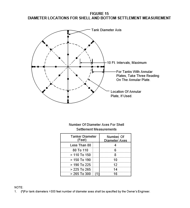
- Shell settlement measurements shall be made after tank erection, prior to hydrostatic testing and during water filling at 50%, 75% and 100% of the maximum filling height of the tank. Settlement measurements shall be taken at equally spaced intervals of approximately 30 feet around the tank shell on well marked locations on the annular plate or on clips welded to the shell, see Figure 15.
- (*)Bottom internal measurements shall be made before and after hydrostatic testing for fixed roof tanks. Such measurements shall be made at 10 foot intervals on the diameter as indicated in Figure 15. If required by the Owner’s Engineer, additional bottom elevation readings shall be taken for external floating roof tanks at a minimum of three fill heights – 50%, 75% and 100% of the maximum fill height. The procedure for obtaining these readings shall be as follows:
- Identify two rows of support legs on the floating roof that are approximately perpendicular to each other.
- After the roof is floating, remove the legs at the identified locations.
- For each measurement location, determine the distance from the top of the leg extension to the tank bottom using a plumb bob and calibrated string or similar device.
- For each measurement location, determine the elevation of top of the leg extension by performing an elevation survey, with the surveying instrument located on the platform space available at the rim of the tank.
- From the previous measurements, calculate tank bottom elevations.
- Additional settlement measurements shall be made before and after hydrotest in the annular plate region, see Figure 15.
- A 100% visual examination shall be made of the tank bottom to detect any localized depressions. The location and extent of depressions shall be indicated on the tank bottom plate layout drawing.
- If the settlements determined from the before and after hydrotest measurements exceed the criteria given in API 653, the tank shall be releveled and re-hydrotested, or evaluated in accordance with EP 4–2–10.
SUPPLEMENTAL REQUIREMENTS FOR SHOP FABRICATED TANKS
- General
The supplemental requirements of this section shall be used for all shop fabricated tanks.
Bottom Design
- Bottom joints shall be butt welded with complete penetration and complete fusion.
- The minimum nominal plate thickness for carbon steel bottoms shall be 1/4 inch, exclusive of any corrosion allowance. The minimum thickness of stainless steel bottoms shall be 3/16 inch.
Anchor Bolts
- Anchor bolts shall be provided when required to resist overturning or uplift due to internal pressure, wind or seismic forces:
- Anchor bolts shall not be less than 1–1/4 inches in diameter.
- Attachment of anchor bolts to the shell shall be through chair–type assemblies of sufficient size to distribute the load over a reasonable area of the shell. Chair height shall be at least 12 inches.
- The anchors shall be designed to withstand the design loading in the most severe of the following two conditions:
- Full of water
- Empty with the tank in the corroded condition.
- The effect of insulation and platforms shall be considered in the wind loading calculation.
Shell Nozzles and Manways
- The wall thickness, excluding corrosion allowance of shell nozzles, shall be at least Sch 80 for carbon steel nozzles, in sizes less than NPS 8.
- Plate–ring flanges shall not be used on shell nozzles. They are permitted for manhole flanges and roof connections. Shell nozzles shall have Class 150, forged steel, slip–on or weld neck flanges.
Insulation Supports
- The welding of insulation and fireproofing support rings or clips shall be done in the shop before PWHT. All insulation and fireproofing supports shall be located at a minimum distance of 4 inches from all vessel seam welds. “Rat–holes” shall be used on insulation rings that cross vessel longitudinal seams to meet this requirement.
- Welding pins, when required for insulation support, shall be installed before PWHT. Hammer testing of pins is required. Testing shall begin immediately after completion of the first few welds. Pins shall be Nelson type TPC or an approved equal. Pin shall be 1/2 inch longer than the insulation thickness. Weld tip of pins shall be free of cadmium plating and other contaminants.
Post Weld Heat Treatment (PWHT)
- PWHT shall be in accordance with EP 9–1–2.
- When PWHT is specified, the PWHT operation shall be performed after all welding is completed.
17.0 TABLES
TABLE 1
PERMISSIBLE MATERIALS FOR TANK CONSTRUCTION
| Components | Industry Standards |
|---|---|
| Shell and Annular Plates | A36 modified (1), A285, A442, A516, A573, A633 |
| Bottom Plates | A36 modified (1), A283, A285, A442, A516, A573, A633 |
| Fixed Roof Plates | A36 modified (1), A283, A285, A442, A516, A573, A633 |
| Floating Roof Plates | A36 modified (1), A283, A285, A442, A516, A573, A633 |
| Sheets for Fixed and Floating Roofs | A570, Grade 33 (2) |
| Structural Shapes | A36, A131 |
| Pipe | API 5L–Grade B; A106–Grades A,B; A333–Grades 1,6; A334–Grades 1,6; A524; A671–Grades CC60, CC65, CC70, CE55, CE60 (3) |
| Forgings | A105; A181; A350–Grades LFI, LF2 |
| Bolting - Flanges | Per EP 5–2–2 |
| Bolting - Structural | A307 |
NOTES:
- Must be killed or semi–killed. Manganese content shall be 0.08–1 .20 percent by heat analysis for all thicknesses. Maximum carbon content must not exceed 0.20 percent
- Material shall be produced only by the open hearth or basic oxygen process.
- Use Class 22 and 33.
TABLE 2
MINIMUM DESIGN METAL TEMPERATURES FOR MATERIAL SELECTION
| Location | Lowest One–Day Mean Temperature (°F) (1) | Minimum Design Metal Temperature (°F) (2) |
|---|---|---|
| Aruba | 45 | 60 |
NOTES:
- From Figure 2–2 of API–650.
- The lowest One–day mean temperature plus 15°F.
TABLE 3
BOTTOM DESIGN CATEGORIES
| Category of Bottom Specified | Predicted Settlement (2) Maximum at Shell |
Annular Plate Width and Bottom Plate Welding Requirements | Annular Plate Width and Bottom Plate Welding Requirements |
|---|---|---|---|
| Tank Diameter (1) Over 50 ft to 150 ft |
Tank Diameter Over 150 ft | ||
| 1 | 2 in. | *Annular plates shall be per API 650. Bottom plates shall be two pass welded when specified by the Owner’s Engineer. | Annular plates shall provide a minimum radial width of 2 ft. between the inside of the shell and any lap-welded joint in the bottom. Bottom plates shall be two pass welded with a minimum joint efficiency of 70%. (4) |
| 2 | 6 in. | Annular Plates shall provide a minimum radial width of 2 ft between the inside of the shell and any lap-welded joint in the bottom. Bottom plates shall be two pass welded with a minimum joint efficiency of 70%. (4) | Annular plates shall provide a minimum radial width of 3 ft between the inside of shell and any lap-welded joint in the bottom. Bottom plates shall be two pass welded with a minimum joint efficiency of 70%. (4) |
| 3 | 12 in. (3) | Annular Plates shall provide a minimum radial width of 2ft between the inside of the shell and any lap welded joint in the bottom. Bottom plates shall be two pass welded with a minimum joint efficiency of 70%. (4) | Annular plates shall provide a minimum radial width of 3 ft between the inside of shell and any lap welded joint in the bottom. Bottom plates shall be two pass welded with a minimum joint efficiency of 80%. (4) |
NOTES:
- No special requirements for tanks 50 feet and under in diameter.
- Predicted settlement includes initial water loading of the tank
- If this settlement is exceeded, some form of site improvement is required prior to tank erection. Soil improvements will be done by Purchaser or Manufacturer, as specified in EP 4–2–7.
Weld procedures and qualifications to achieve the stipulated weld efficiency for bottom plate fillet welded joint are covered in EP 9–1–2.
TABLE 4
MINIMUM TANK COURSE SHELL THICKNESS
| Nominal Tank Diameter (feet) (1) | Minimum Plate Thickness (inches) |
|---|---|
| 120 | 1/4 |
| 120 to 200 | 5/16 |
| 200 to 250 | 3/8 |
| 250 | 7/16 |
NOTE:
(1) The centerline diameter of the bottom shell course.
TABLE 5
SIZE AND NUMBER OF SHELL MANHOLES
| Tank Diameter (feet) | Minimum Number of Manholes | Minimum Manhole Size (NPS–inches) |
|---|---|---|
| 25 | 1 | 24 |
| 25 to 100 | 2 | 24 |
| 100 to 150 | 3 | 24 |
| 150 to 250 | 4 | 24 |
| 250 | 5 | 24 |
TABLE 6
REQUIRED WALL THICKNESS OF ROOF NOZZLES
| Nozzle Size (NPS) | Nozzle Thickness |
|---|---|
| 1–1/2 to 2 | SCH 160 |
| 3 to 4 | SCH 80 |
| 8 to 24 | SCH 40 |
TABLE 7
SIZE AND NUMBER OF ROOF MANWAYS
| Tank Diameter (feet) | Minimum Number of Manways | Minimum Manway Size (NPS) |
|---|---|---|
| <50 | 1 | 24 |
| 50 to 100 | 2 | 24 |
| >100 | 3 | 24 |
TABLE 8
MINIMUM THICKNESS OF PONTOON RIMS
| Tank Diameter (feet) | Inner Rim Thickness (inches) | Outer Rim Thickness (inches) |
|---|---|---|
| 200 to 250 | 5/8 | 1/4 |
| >250 to 300 | 3/4 | 5/16 |
TABLE 9
INTERNAL FLOATING ROOF MANWAY REQUIREMENTS
| Internal Cover Diameter (feet) | Minimum Number of Manways | Minimum Manway Size (NPS) |
|---|---|---|
| <50 | 1 | 24 |
| 50 to 100 | 2 | 24 |
| >100 | 3 | 24 |
TABLE 10
DIMENSIONAL TOLERANCES FOR SHELL PLATE
| Dimension | Tolerance (inches) |
|---|---|
| Length Width Difference in diagonals |
±1/16 ±1/16 ±1/8 |

© 2026 Inflection Point Engineering, LLC. All rights reserved. The content of this page — including calculation methods, reference data, written analysis, interactive tools, and source code — is the intellectual property of Inflection Point Engineering, LLC and is protected under applicable copyright, trademark, and trade secret laws. Unauthorized reproduction, redistribution, modification, or derivative use in whole or in part is prohibited without prior written consent.
Disclaimer. This material is provided for informational and educational purposes only and does not constitute professional engineering advice. Calculations, reference data, and methodologies are based on published standards and accepted engineering practice but are not a substitute for engineering judgment, site-specific analysis, or review by a licensed Professional Engineer. Inflection Point Engineering, LLC makes no warranties, express or implied, regarding the accuracy, completeness, or fitness for a particular purpose of any content presented here, and shall not be liable for any direct, indirect, incidental, or consequential damages arising from its use. Users assume all risk associated with applying this content to real-world design, operations, or decisions.
© 2026 Inflection Point Engineering, LLC. All rights reserved.