 Section 8 — Heat Transfer Equipment
Fired Heaters
IPE Engineering Practice IPE-EP-8-2-1
Document number: IPE-EP-8-2-1 · Section: 8 — Heat Transfer Equipment
The following paragraph numbers refer to API 560, third edition, which is part of this Practice. Paragraphs denoted as "New" are additional requirements for which there are no corresponding paragraphs in API 560.
GENERAL
- Scope
1.1.1 This Practice, EP 8-2-1DS data sheets (16 pages), all referenced publications listed in paragraph 1.6, and the requirements of API Standard 560, third edition, govern the requirements for the purchase, design, materials, fabrication, inspection, testing, preparation for shipment and erection of fired heaters, air preheaters, fans, and burners.
- (New) Manufacturers supplying heaters fitted with steam coils in the State of Ohio must submit to the Ohio Department of Industrial Relations, Pressure Piping Division, two copies of each welder performance qualification test report. One copy will be returned to the sender approved for fabrication, with or without comments. This requirement is Ohio State Law and no exceptions will be permitted.
- (New) This Practice is written using the same numbering system as in APl Standard 560. Paragraphs marked with a bullet (●) correspond to paragraphs where a Purchaser decision is required.
- (New) Any deviations from this Practice or Practices referenced herein must be approved by the procedure described in EP 1-1-3.
- Conflicting Requirements
1.3.1 In case of conflict between this Practice and the referenced publications, including API 560, this Practice shall take precedence.
- Definition of Terms
The following definitions shall be included with the list given in API 560; An Inspector is a Inflection Point Engineering, LLC appointed engineer or inspector.
A Manufacturer is the recipient of a direct or indirect purchase order for materials and/or equipment. In this context, a direct purchase order is one issued to a Manufacturer by a contractor or the Owner. An indirect order is one issued to a Manufacturer by a vendor (recipient of a direct purchase order) for materials, fabricated components, or subassemblies.
The Owner is Inflection Point Engineering, LLC.
An Owner's Engineer is a Inflection Point Engineering, LLC appointed engineer.
The Purchaser is the party placing a direct purchase order. The Purchaser is the Owner's designated representative.
1.6 Referenced Publications
1.6.3 (New) In addition to the publications referenced in API 560, the following standards and publications are also referred to herein and form part of this Practice:
STANDARDS AND PUBLICATIONS
| The Engineering Practices |
|---|
| EP 1-1-3 Deviations to The IPE Engineering Practices EP 4-1-1 Design Criteria and Loads for Structures EP 4-5-1 Structural Steel EP 4-5-3 Auxiliary Structures for Operation and Maintenance EP 5-2-2 Flanges, Gaskets and Bolting EP 5-5-1 Piping Fabrication EP 5-5-2 Welding Requirements for Piping EP 5-5-3 Piping Erection and Testing EP 5-6-3 Piping for Fired Heaters EP 6-6-1 Centrifugal Fans in General Plant Services EP 8-2-1 DS Fired Heaters Data Sheet EP 8-2-2 Sootblowers EP 8-2-3 Wet Steam - Air Decoking Systems EP 10-2-4 Statically Cast Steel and Alloy Pressure Containing Parts and Tube Supports for Fired Heaters EP 11-1-2 Fired Heater Refractory EP 13-3-1 Induction Motors NEMA Frame EP 13-3-2 Induction Motors Above 200HP EP 15-1-4 Positive Materials Identification (PMI) |
| ASME Codes |
| Sec I Power Boiler Code Sec VIII, Div 1 Pressure Vessel Code Sec V Nondestructive Examination |
| ANSI Standards |
| A12.1 Safety Requirements for Floor and Wall Openings A14.3 Safety Code for Fixed Ladders |
| API Publications |
| RP530 Recommended Practice for Calculation of Heater Tube Thickness in Petroleum Refineries RP533 Air Preheater Systems for Fired Process Heaters |
- Proposals
PURCHASER'S RESPONSIBILITIES
1.8.1.4 Four copies of all documentation listed in 1.8 and 1.9 shall be furnished to the Owner.
VENDOR'S RESPONSIBILITIES
1.8.2.f Curves shall be provided for heaters in vaporizing service showing pressure, temperature, vaporization, and bulk velocity of the fluid as a function of the tube number for the design case and other operating cases as specified in the data sheets.
- Documentation
CERTIFIED DRAWINGS AND DIAGRAMS
- After receipt of the Purchaser's comments on the general arrangement drawings and foundation loading diagrams, the Manufacturer shall furnish certified general arrangement drawings and foundation loading diagrams. One reproducible and four copies of each general arrangement drawing shall be furnished to the Owner. Before starting fabrication, the Manufacturer shall furnish four copies of all design detail drawings, erection drawings, and an erection sequence for the Owner's Engineer's approval. Fabrication shall not begin without the Owner's Engineer's written approval. Owner's Engineer's review of these drawings shall not relieve the manufacturer of the responsibility for complying with the requirements of this practice.
The drawings shall include the following:
- Heat treatment requirements
- Non-destructive testing including hydrostatic test requirements
- Hardness requirements
- Gasket details
- All other details needed for maintenance and repairs
- Painting requirements
- Details of all auxiliary equipment and controls
- All weld joint details in cross section, their locations, and applicable welding procedures
- Alloy electrode designation, when applicable
- Bolting Requirements
The drawings shall include the following notes:
- "The root pass of two-sided welds shall be backgouged and liquid penetrant or magnetic particle examined prior to welding from the opposite side."
- "All nozzles and couplings shall be backgouged to clean metal and magnetic particle or liquid penetrant inspected prior to welding from the opposite side."
FINAL RECORDS
Within 10 days after the completion of the heater shipment, the manufacturer shall furnish the Owner with three copies of the documents list below. If modifications are required, copies of "as-built" drawings (only those affected) shall be issued to the Owner.
- All other documents listed in this paragraph of API 560
- Code stamping facsimiles
- Heat treatment charts
- Radiographic records
- Hydrostatic test charts or certification
- Welder and welding procedure qualification reports
- Brinell hardness reports
- Magnetic particle and/or liquid penetrant inspection reports
- Process temperature and pressure profiles for the heater at design conditions
- (New) DESIGN CALCULATIONS
- Design calculations shall be furnished for all components designed in accordance with the ASME Code. Symbols and abbreviations shall match those in the ASME Code or shall be fully defined. Calculations determining tube wall thickness using API 530 procedures shall be submitted for review and approval by Owner's Engineer.
DESIGN CONSIDERATIONS
- Process
- (New) The maximum flux density at any point in the convection or shield sections, based on bare surface, shall not exceed the maximum flux density occurring in the radiant section.
- ● (New) The minimum convection section tube metal temperature shall be a minimum of 25 °F above the anticipated flue gas dew point temperature for the design fuel(s). Calculations to substantiate the dew point temperature shall be made available to the Owner's Engineer upon request.
2.2 Combustion
2.2.6 Heaters shall be designed such that a negative pressure of at least 0.05 inches of water column is maintained in the radiant and convection sections at 125 percent of the heat release required for the design duty with 90 °F ambient air temperature and 25 percent excess air.
2.3 Mechanical
2.3.8 Convection section corbels are required.
- (New) For wall fired heaters, the minimum clearance from grade to floor shall be 2 feet 6 inches.
- (New) The maximum noise level resulting from any fired heater operating at the design firing rate shall not exceed 85 dB-A as measured in four locations, three feet from the perimeter of the heater at an elevation of five feet. Refer to The Recommended Environmental Guidelines for additional requirements.
- (New) The heater Manufacturer shall supply guaranteed octave band and dB-A data to the Owner with information that explains the basis of the guaranteed value.
- (New) Air cooled walls separating fireboxes of multi-cell heaters are required. The use of hot separating walls consisting of solid refractory is not permitted.
TUBES
- General
- ● Calculations to substantiate tube temperature and wall thickness shall be made available to Owner's Engineer upon request. The minimum thickness for new tubes shall be as shown in Table 4.
- Extended Surface
- Both studded and continuously welded fin tubes as described by API 560 are acceptable. The use of serrated fins shall not be permitted.
- The maximum fin tip temperature for carbon steel shall be 800 °F and for 11-13 Cr shall be 1050 °F. The maximum stud tip temperature shall be as given in API 560.
3.2.3. Extended surface dimensions shall be limited to the dimensions given in API 560 except that the minimum fin thickness for gas fired heaters shall be 0.06 inch and the maximum fin density for gas fired heaters shall be 4/inch. All other maximum or minimum dimensions shall remain as specified in API 560.
3.2.4 (New) Each end of a continuously welded fin shall be secured to the tube using a 1 inch long fillet weld.
4.0 HEADERS
Headers shall be in accordance with API 560.
PIPING, TERMINALS, AND MANIFOLDS
- General
- Flanges, gaskets and bolting shall be in accordance with EP 5-2-2.
- Piping, terminals and manifolds external to the enclosure shall be in accordance with
EP 5-5-1, EP 5-5-2, EP 5-5-3, EP 5-6-3 and the additional requirements of this Practice.
- ● When inspection openings are required, plug type return bends shall be provided as per the Fired Heater Data Sheet, EP 8-2-1 DS.
- All couplings shall be Class 6000, forged steel, full threaded, and be welded in rather than welded on.
- Low point drains and high point vents are required except for heaters with vertical tube serpentine coils in which case no vents or drains are required.
5.1.9 ● (New) Manifolds shall have extruded rather than welded in stubs, except as approved by the Owner's Engineer in writing. When the extruded manifolds are carbon steel, stress relieving is required. When the manifolds are stainless steel, solution annealing is required.
5.3 Materials
(New) All attachments, clips, lugs, and guides welded to radiant or convection tubes shall be of the same material as the tube.
TUBE SUPPORTS
- General
6.1.3 ● The unsupported length of horizontal tubes (NPS 8 inch and smaller) shall not exceed 35 times the outside diameter, or 20 feet, whichever is less. For tube diameters greater than NPS 8 inch, the unsupported tube length can be more than 20 feet but shall not exceed 35 times the outside diameter. Calculations on tube deflection for support greater than 20 feet shall be submitted for review and approval by the Owner's Engineer.
6.1.5.4 Sleeves with an inside diameter at least 1/2 inch (13 millimeters) greater than the tube or the extended surface outside diameter shall be welded to the tube sheet at each tube hole, to prevent the refractory from being damaged by the tubes. The sleeve material shall be Type 304 stainless steel or equal throughout the convection section.
6.1.6.4 (New) For finned tubes a minimum support saddle width of 2 inches shall be provided.
- (New) Vertical tubes supported at the bottom end shall have guide supports at a spacing of 50 outside tube diameters, except that the maximum spacing between guides or guides and end supports shall not exceed 25 feet.
- (New) Convection section end tube supports, and intermediate tube supports (where applicable), shall have provisions to accommodate two additional rows of tubes. The stainless steel sleeves shall be attached and filled with refractory for the tubes in these two rows. In addition, the structural plate shall be partially cut to indicate the position of the sleeves.
- (New) The Manufacturer shall include the cost adder for including intermediate tube supports for the two additional rows of convection tubes required in paragraph 2.3.4 of API 560.
- Loads and Allowable Stress
6.2.2 The allowable stresses for design shall be in accordance with Table 1, Table 2, and Table 3. Linear interpolation shall be used for intermediate design temperatures. Material shall not be used at temperatures higher than those where an allowable stress value is provided.
- Materials
6.3.1 ● Permissible tube support materials and maximum design temperature shall be in accordance with Table 1, Table 2, and Table 3. Unless otherwise specified by the Owner's Engineer, exposed radiant section tube supports shall be HK-40.
In Table 8 of API 560, the casting type for the material composition 25 Cr-20 Ni should be expanded to read "A297 Gr HK or A351 Gr HK40 (minimum of 0.35% by weight carbon)."
7.0 REFRACTORIES AND INSULATION
The refractory system design, installation, and testing shall be in accordance with EP 11-1-2
STRUCTURES AND APPURTENANCES
- General
8.1.2 Minimum design loads for wind and earthquake shall conform to the requirements of the International Conference of Building Officials (Uniform Building Code).
8.1.3 thru 8.1.7
In addition to the codes and specifications cited by API 560, structural steel, ladders and platforms shall be designed in accordance with EP 4-5-1 and EP 4-5-3.
8.3 Header Boxes, Doors, and Ports
8.3.1 HEADER BOXES
8.3.1.2 Header boxes enclosing plug type return bends shall have hinged doors. Doors shall be hinged on their long side to open either sideways or downward.
8.3.1.5 (New) Header boxes shall be of sufficient size to provide ample work space for cleaning and replacing tube and return bends. They shall be at least 25 inches wide to permit the use of impact wrenches on return bend plugs. There shall be an 8 inch minimum clearance distance between return bends and the top, side, and bottom of compartment inside surface. The tubes should extend a minimum of 6 inches beyond the tube sheet for welding to the return heads.
8.3.2 DOORS AND PORTS
8.3.2.7 (New) Doors shall be provided to give inspection access for each convection section. When sootblower lanes are present, one door shall be provided for each lane. When sootblower lanes are not present, one door shall be provided for each convection coil. The doors shall be a minimum size of 12 inches X 6 inches and be placed to give maximum view of the tubes.
- Ladders, Platforms, and Stairways
8.4.1.b Horizontal cabin heaters with plug type return bends shall have a platform to service the roof tubes for maintenance purposes. One platform shall be provided for each end with plug return bends. Platforms serving convection section ends are not required above a return bend platform.
- Platforms shall have a minimum clear width and access as follows:
- Operating platforms - 3 feet 0 inches. Access to the platform is to be by one ladder at one end and one set of stairs per platform at the opposite end of the platform.
- Maintenance platform - 6 feet 0 inches. Access to the platform is to be by a ladder at each side of the platform except for the damper platform which requires only one ladder.
- Walkways - 2 feet 6 inches.
- ● Platform decking shall be 1 inch by 3/16 inch open grating or 1/4 inch checkered plate as specified by Owner's Engineer. See EP 4-5-3.
8.4.7 Ladders shall have twisted rungs and shall be side exit and entering.
STACKS, DUCTS, AND BREECHING
- General
9.1.1 Stacks shall be self-supporting and shall be designed in accordance with EP 4-1-1 and the additional requirements given in this Practice.
9.1.6 An expansion joint made of materials capable of withstanding the flue gas temperature shall be included for each duct. The expansion joint shall have a bolted flanged joint at both the breeching and stack sides.
- When operating with natural draft, a control damper shall be furnished in each heater stack.
- (New) One stack or flue gas duct opening above the convection section shall be furnished for every 40 feet of convection section tube length.
- (New) The stack shall be equipped with a painters' trolley, trolley ring, and trolley rigging.
- Design Considerations
9.2.2 Minimum design loads for wind and earthquakes shall conform to the requirements of EP 4-1-1.
9.6 Materials
9.6.3 Dampers and shafts shall be solution annealed, thermally stabilized AISI Type 321 stainless steel for flue gas temperatures up to 1500 °F and 25 Cr-12 Ni up to 1800 °F.
BURNERS, SOOTBLOWERS, AND DAMPER CONTROLS
- Burners
10.1.3 For natural draft operation, with burners firing vertically or horizontally, an additional 6" over the minimum clearance listed in column B of Table 12 of API 560 shall be provided. For intermediate firing rates, the required clearances given in Table 12 shall be based upon the higher heat release. Linear interpolation shall not be used.
10.1.6 Gas pilots shall be provided for all burners. Pilots shall be of the high stability type fitted with flame retention heads.
10.1.10 The flame stabilizer or cone shall be constructed of Inconel 601 or equal. The 300 series stainless steel listed in Table 13 of API STD 560 for this component is not acceptable.
- (New) Spare oil guns shall be provided with the heater. The number of spares shall be at least 20 percent of the total number of oil burners.
- ● (New) A test firing, witnessed by the Owner's Engineer, of at least one production burner at random shall be performed for each different type or size of burner for compliance with the Data Sheet specifications.
- ● (New) Minimum gas port opening shall be 0.10" unless otherwise approved by Owner's Engineer.
10.2 Sootblowers
10.2.5 ● Convection section walls in the sootblowing lanes shall be protected by either high-duty fireclay brick or castable refractory with a minimum density of 125 pounds per cubic foot (2,000 kilograms per cubic meter) on four sides. When oil is specified as a design fuel, sootblowers shall be provided in accordance with EP 8-2-2.
- (New) Steam-Air Decoking Systems
- The requirements for steam-air decoking systems, when specified by the Owner's Engineer, shall be in accordance with EP 8-2-3.
- (New) Air Preheat Systems
- The requirements for air preheat systems, when specified by the Owner's Engineer, shall be in accordance with Appendix E of API 560.
CENTRIFUGAL FANS AND DRIVERS FOR FIRED HEATER SYSTEMS
- General
11.1.1 All fans shall be in accordance with API 560 and EP 6-6-1. All drivers shall be in accordance with API 560, EP 13-3-1, and EP 13-3-2.
12.0 INSTRUMENT AND AUXILIARY CONNECTIONS
12.3 Auxiliary Connections
12.3.2 VENT AND DRAIN CONNECTIONS
12.3.2.1 Manifold or piping vents and drains shall be a minimum NPS 1-inch, 6000-pound welded coupling, of the same metallurgy as the manifold or piping.
- Tube-Skin Thermocouples
- In addition to the API requirements, tube-skin thermocouples shall be manufactured by the Thermo-Couple Products Co., Inc., or approved equal, and be installed per manufacturers instructions. Specific requirements for numbers and locations of thermocouples will be per specifications in the Fired Heater Data Sheet, EP 8-2-1DS.
SHOP FABRICATION AND FIELD ERECTION
- General
13.1.4. Fabrication of piping shall be in accordance with EP 5-6-3. Structural welding shall be in accordance with the Structural Welding Code, AWS D1 .1.
13.1.6. ● (New) Written approval shall be obtained from Owner's Engineer before any welding, preparation for welding, fabrication, or forming, including bending and rolling, is subcontracted to another shop or supplier.
- Steel Fabrication
- Seam welds between plates shall be continuous full penetration welds except that girth and longitudinal joints in stack sections shall be double-butt welded. The butt welded joints shall be backchipped to sound metal before welding from the opposite side.
- All exterior welds, including horizontal, vertical, and diagonal, between the plates and the structural members shall have continuous fillet welds on both sides.
13.2.8 Anchor attachment by manual or stud-gun are both acceptable. When stud-gun welding is used, surfaces shall be ground and sand blasted prior to stud attachment. See EP 11-1-2 for complete anchor attachment and inspection requirements.
13.3 Coil Fabrication
In addition to the API requirements, coil fabrication shall be in accordance with EP 5-5-1.
13.6 PREPARATION FOR SHIPMENT
13.6.1 Suitable bracing and supports shall be provided by the Manufacturer to prevent damage to the heater components during shipment. The Manufacturer shall be responsible for adequacy of the provisions employed when handled by commercial carrier systems. All temporary bracing and supports shall be painted yellow to denote required removal before operation.
- The flange gasket and bolt circle surfaces shall be coated with a heavy grease (MlL-G- 23827A) and have a full rubberized gasket covered with 1/4 inch metal or plastic plate held in place with at least four steel clips or bolts.
- After the hydrostatic test, the Manufacturer shall lubricate the plug, plug seating surface, and threaded parts of plug type return bends with an antirust, anti-seize lubricant.
- (New) The flanges shall be covered with two layers of Marvelpac #12 (MIL-B-121-C, Type I, Class II Grade C), including both sides of the bolt holes, and secured with a rubber-backed waterproof tape.
- (New) Threads of bolts shall be heavily coated with a metallic base waterproof lubricant. For low alloy studs "Never Seez" or equal shall be used. "Never Seez" is manufactured by Never Seez Compound Corporation, Broadview, Ill. 60153.
INSPECTION, EXAMINATION AND TESTING
- General
14.1.2 ● All material and fabrication are subject to inspection by an Owner's representative. Rejections by the inspector are final. The Owner's inspection does not relieve the Manufacturer of the responsibility for complying with the requirements of the purchase order.
14.1.4 The Manufacturer shall advise the Owner's Inspection Department at least five working days before: starting and completing fabrication, hold points, specified testing, and preparation for shipment.
- Weld Inspection and Examination
- Weld inspection shall be in accordance with EP 5-6-3 and the additional requirements of this Practice.
- All welds shall be 100% radiographed.
14.2.2.8 ● (New) Inspection of stack welding shall include one radiograph of each junction and one intermediate shot of all longitudinal welds. The cost of these radiographs shall be included in the contract price. All radiograph films, properly identified shall be submitted to the Owner's Engineer for approval. The minimum film length shall be 10 inches.
- All film shall be kept for until the job is completed. Two additional radiographs of rejects showing defects in welds shall be kept until the job is completed.
- (New) All repaired welds shall be radiographed and the films of the repairs shall be marked "R" besides being positively identified as the original film.
- Casting Examination
- Cast Convection Tube Supports shall be inspected in accordance with EP 10-2-4.
- Cast Radiant Tube Supports shall be inspected in accordance with EP 10-2-4.
14.5 Testing
14.5.1 PRESSURE TESTING
14.5.1.1 In addition to the test requirements given in API 560 (a and b), the following apply:
- The test pressure shall be applied so as to vent all possible air from tubes.
- No drop in pressure or leaks shall be permitted except pressure drop due to incidental temperature change.
- The hydrotest shall be repeated after completion of repairs, if any.
14.5.4 POSITIVE MATERIALS IDENTIFICATION
14.5.4.2 Positive Materials Identification (PMI) shall be in accordance with EP 15-1-4.
15.0 TABLES
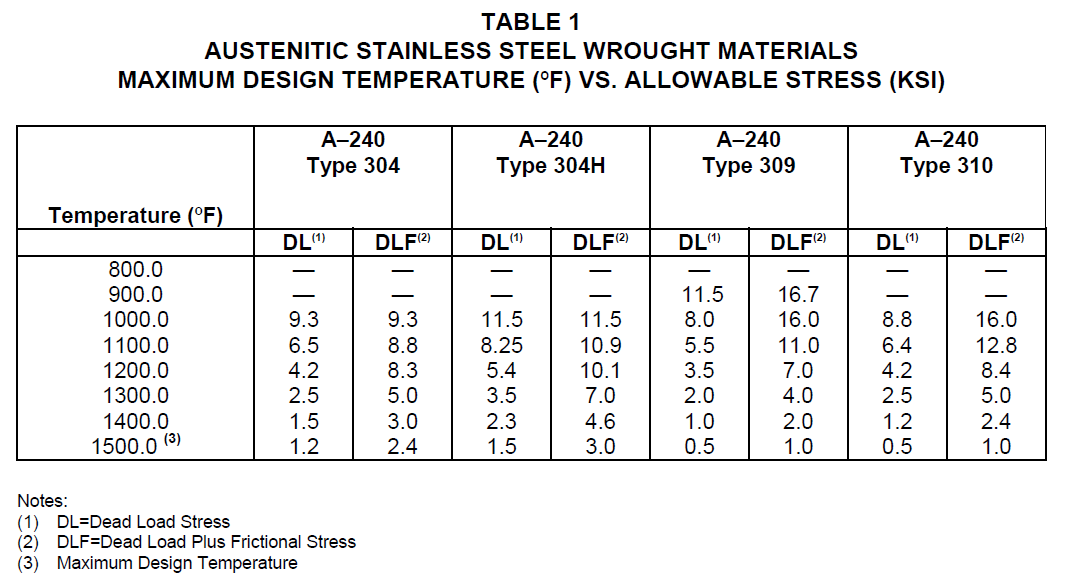
TABLE 2
HIGH ALLOY WROUGHT MATERIALS
MAXIMUM DESIGN TEMPERATURE (°F) VS. ALLOWABLE STRESS (KSI)
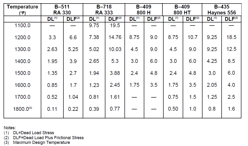
TABLE 3
HIGH ALLOY CAST MATERIALS
MAXIMUM DESIGN TEMPERATURE (°F) VS ALLOWABLE STRESS (Ksi)
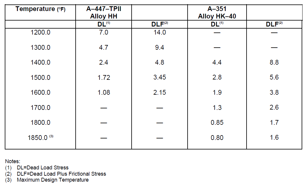
TABLE 4
MINIMUM THICKNESS FOR NEW TUBES
| Outside Diameter | Minimum Wall Thickness |
|---|---|
| NPS 2-1/2 inch and smaller | 3/16 inch |
| NPS 3 to NPS 5 inch(inclusive) | 1/4 inch |
| NPS 6 inch and larger | Schedule 40 |
TABLE 5 DOCUMENTATION REQUIREMENTS FOR FIRED HEATERS PER EP 8-2-1
| Item | Description | Format | As-Built |
|---|---|---|---|
| 1 | Certified general arrangement drawings per API 560 | See EP 2-5-2 | Yes |
| 2 | Foundation loading diagrams API 560 | See EP 2-5-2 | Yes |
| 3 | Structural steel drawings; details of stacks, ducts, and dampers | See EP 2-5-2 | Yes |
| 4 | Structural calculations | See EP 2-5-2 | Yes |
| 5 | Burner assembly drawings and burner piping | See EP 2-5-2 | Yes |
| 6 | Tube support details | See EP 2-5-2 | Yes |
| 7 | Thermowell and thermocouple details | See EP 2-5-2 | Yes |
| 8 | Welding, examination, and test procedures | See EP 2-5-2 | Yes |
| 9 | Installation, dry out, and test procedures for refractories and insulation | See EP 2-5-2 | Yes |
| 10 | Refractory thickness calculations | See EP 2-5-2 | Yes |
| 11 | Decoking procedures | See EP 2-5-2 | Yes |
| 12 | Detailed design drawings including those of auxiliary equipment EP 8-2-1 | See EP 2-5-2 | Yes |
| 13 | Erection drawings with erection sequence | See EP 2-5-2 | Yes |
| 14 | Completed Fired Heater data sheet (EP 8-2-1 DS) | See EP 2-5-2 | Yes |
| 15 | Certified material reports, mill test reports, or ladle analysis for all pressure parts and alloy extended surfaces | See EP 2-5-2 | Yes |
| 16 | Installation, operation, and maintenance instructions for the heater and auxiliary equipment, such as air preheaters, fans, drivers, burners | See EP 2-5-2 | Yes |
| 17 | Performance curves or data sheets for air preheaters, fans, drivers, and burners and other auxiliary equipment |
See EP 2-5-2 | Yes |
| 18 | Bill of materials | See EP 2-5-2 | Yes |
| 19 | Noise data sheets | See EP 2-5-2 | Yes |
| 20 | Refractory dry-out procedures | See EP 2-5-2 | Yes |
| 21 | Code stamping facsimiles | See EP 2-5-2 | Yes |
| 22 | Heat treatment records | See EP 2-5-2 | Yes |
| 23 | Radiographic records | See EP 2-5-2 | Yes |
| 24 | Hydrostatic test charts or certification | See EP 2-5-2 | Yes |
| 25 | Welder and welding procedure qualification reports | See EP 2-5-2 | Yes |
| 26 | Brinell hardness reports | See EP 2-5-2 | Yes |
| 27 | Magnetic particle and/or liquid penetrant inspection reports | See EP 2-5-2 | Yes |
| 28 | Process temperature and pressure profiles for the heater at design conditions | See EP 2-5-2 | Yes |
| 29 | ASME/API 530 design calculations per EP 8-2-1 | See EP 2-5-2 | Yes |
16.0 APPENDIX E - CENTRIFUGAL FANS FOR FIRED HEATER SYSTEMS
E.2 General Considerations
E.2.1 APPLICATION CONSIDERATIONS
Air preheating becomes more attractive with increased fired heater process inlet temperature or duty.
© 2026 Inflection Point Engineering, LLC. All rights reserved. The content of this page — including calculation methods, reference data, written analysis, interactive tools, and source code — is the intellectual property of Inflection Point Engineering, LLC and is protected under applicable copyright, trademark, and trade secret laws. Unauthorized reproduction, redistribution, modification, or derivative use in whole or in part is prohibited without prior written consent.
Disclaimer. This material is provided for informational and educational purposes only and does not constitute professional engineering advice. Calculations, reference data, and methodologies are based on published standards and accepted engineering practice but are not a substitute for engineering judgment, site-specific analysis, or review by a licensed Professional Engineer. Inflection Point Engineering, LLC makes no warranties, express or implied, regarding the accuracy, completeness, or fitness for a particular purpose of any content presented here, and shall not be liable for any direct, indirect, incidental, or consequential damages arising from its use. Users assume all risk associated with applying this content to real-world design, operations, or decisions.
© 2026 Inflection Point Engineering, LLC. All rights reserved.