 Section 8 — Heat Transfer Equipment
Plate and Frame Heat Exchangers
IPE Engineering Practice IPE-EP-8-1-7
Document number: IPE-EP-8-1-7 · Section: 8 — Heat Transfer Equipment
SCOPE
- This Practice governs the general requirements for the design, fabrication, materials, and shipping for plate and frame heat exchangers for use in refining services.
- This Practice is a purchase specification when accompanied by the herein referenced IPE Engineering Practices and the completed Data Sheet from EP 8–1–7 DS required by this Practice.
- Any exceptions to this Practice must be explicitly stated by the Manufacturer in his bid inquiry. Deviations to this Practice must be approved by the procedure given in EP 1–1–3.
- An asterisk (*) indicates that a decision by the Owner or Owner’s Engineer is required, or that additional information is furnished by the Purchaser.
- A revision bar indicates all changes made to this Revision.
2.0 REFERENCES
The latest edition of the following standards and publications shall be referred to herein.
STANDARDS AND PUBLICATIONS
| IPE Engineering Practices |
|---|
| EP 1–1–3 Deviations to IPE Engineering Practices EP 5–2–2 Flanges, Gaskets and Bolting EP 7–1–5 Welding Requirements for Pressure Vessels EP 8–1–7 DS Plate and Frame Heat Exchangers Data Sheet EP 10–2–1 Material Requirements for Aggressive Environmental Services EP 10–3–1 Shop Painting EP 15–1–4 Positive Materials Identification (PMI) |
| API Publications |
| Std 662 Plate Type Heat Exchangers for General Refinery Services |
| OSHA |
| Occupational Safety and Health Administration |
DEFINITIONS
- Aggressive Environmental Service (AES) - Process services which result in material degradation such as cracking, scaling, blistering, and severe pitting and/or corrosion. Examples of such services are hydrogen service, wet hydrogen sulfide, cyanides, caustic, amine, and hydrofluoric acid. AES process fluids are defined in EP 10–2–1.
- Carrying Guide Support Column – Extends to the foundation on which the plate heat exchanger is mounted. With the fixed cover it supports the carrying guides.
- Contractor – Company or business that agrees to furnish materials or perform specified services at a specified price and/or rate to the Owner.
- Fixed Cover – Is the stationary end of the exchanger. For single pass units it usually contains all liquid nozzles. It usually extends to the foundation on which the heat exchanger exists.
- Frame – Is that assembly which provides the structural support and the pressure containment for the plate pack. It consists of the fixed cover, movable cover, upper and lower carrying bars, protective metal shroud closing bolts and nuts, and a carrying bar support column, if required.
- Gasket – Each plate is fitted with an attached gasket. The gasket contains the liquids between the plates, properly separates them within the channels, and directs them into the proper flow paths.
- Inspector – A Inflection Point Engineering, LLC appointed engineer or inspector.
- Lower Carrying Guide – Is a guide bar for the plates. It is welded or bolted to the stationary cover and carrying guide support column. It is sheathed in and constructed of stainless steel on those surfaces in contact with the plates.
- Manufacturer – The recipient of a direct or indirect purchase order for materials and/or equipment. In this context, a direct order is one issued to a Manufacturer by a Contractor or the Owner. An indirect order is one issued to a Manufacturer by a vendor (recipient of a direct order) for materials, fabricated components, or subassemblies.
- Movable Cover – Is the movable end of the exchanger. It is supported in a hanger from the upper carrying bar along which it can move, guided by the lower carrying bar.
- Owner – Inflection Point Engineering, LLC.
- Owner’s Engineer – A Inflection Point Engineering, LLC appointed engineer.
- Plate Heat Exchanger – A unit consisting of an assembly of gasketed plates supported in a frame capable of being opened and reclosed, and fitted with nozzles that provide entrance and exit for the heat exchanging fluids.
- Plate Pack – Is the assembly of gasketed plates which forms the alternating channels through which the two heat exchanging liquids flow. The plates separate the hot liquid from the cold and provide the heat transfer surface.
- Purchaser – The party placing a direct purchase order. The Purchaser is the Owner’s designated representative.
- Upper Carrying Guide – Is supported horizontally by the fixed cover and the carrying bar support column, and is welded or bolted to both. A stainless steel cylindrical or steel Tee section may be welded to the guide to provide the mounting member for the plate pack.
DOCUMENTATION AND ADDITIONAL REQUIREMENTS
- (*) The Manufacturer shall furnish as part of the proposal, for the Owner’s Engineer’s approval, one (1) reproducible and three (3) copies of preliminary outline drawings showing overall dimensions; location, size and rating of all connections; foundation bolt location and size; weight empty and full of water; equipment identification; design and test pressures; design temperature; maximum allowable working pressure and the associated temperature; Minimum Design Metal Temperature (MDMT); corrosion allowance; and the applicable codes.
- (*) Prior to fabrication, one (1) reproducible and three (3) copies of detail shop drawings shall be forwarded for the Owner’s Engineer’s review and comments. Upon final revisions, one (1) reproducible set, and three (3) complete copy sets shall be furnished to the Owner. Such drawings shall show all main seam welds; typical welds for flanged and screwed connections in cross section; internal construction details; dimensions of all parts; depth of groove between plates; material specification; weld hardness requirements; alloy weld electrodes; welding procedure identification used for main seams, fitting welds and weld overlay; gasket details; and all details necessary for maintenance and repair.
- (*) Prior to fabrication, the Manufacturer shall submit for review by the Owner’s Engineer, detailed ASME Code calculations for all pressure boundary components.
- (*) The Manufacturer shall furnish the Owner’s Engineer three (3) copies of code and equipment records including: Mill test reports for materials, manufacturer data report, code stamping facsimiles, hydrostatic test charts and certification, welder and welding qualification reports, and correspondence to and from the specific state regulatory body regarding special approval of design, materials, etc.
- The Manufacturer shall apply American Society of Mechanical Engineers (ASME) Code stampings.
- The Manufacturer shall register each exchanger with the National Board of Boiler Pressure Vessel Inspectors.
- (*) The Manufacturer shall comply with all local rules and regulations specified by the Purchaser.
- Drawings with proprietary clauses are unacceptable.
- Details of the plate alignment system, upper and lower guide bars must be submitted as part of the Manufacturer’s bid proposal.
- Prior to fabrication, the Manufacturer shall supply bolting procedures that will guarantee proper gasket compression and plate pack alignment.
GUARANTEE
- The Manufacturer shall guarantee thermal and hydraulic performance of the exchangers, with regard to capacity, heat duty and pressure drop to be in accordance with the process conditions of the Purchase Order.
- The Manufacturer shall guarantee the mechanical design, workmanship, and materials of each exchanger; the guarantee period shall be twelve months after installation, but not more than eighteen months after the shipping date.
- Upon satisfactory proof that the exchangers furnished do not meet specified operating conditions, or if any defective parts or workmanship are found within the guarantee period, the Manufacturer shall, at the Owner’s option, do one of the following:
- At the Manufacturer’s expense, at the Owners Installation, and at the earliest mutually agreed time, make necessary repairs, replacements, and or additions required to correct the deficiency.
- Reimburse the Owner a sum to be agreed upon at that time.
GENERAL DESIGN REQUIREMENTS
- In addition to the requirements of this Practice, plate and frame heat exchangers shall be in accordance with API STD 662.
- (*) Material requirements shall be as specified by the Owner’s Engineer on the Data Sheet of EP 8–1–7 DS.
- The design temperature shall be a minimum of 30 F above the highest operating temperature. The design temperature shall be used for the design metal temperature of the ports, end plates, connector plate and the fixed and movable covers.
- The design pressure shall be a minimum of 25 psi above the maximum operating pressure.
- Connection and port liquid velocities shall not be greater than 10 ft/s for carbon steel and stainless steel. Titanium connections should be limited to 18 ft/s.
- The plate heat exchanger shall be designed and arranged to minimize space requirements.
- Design features to facilitate quick and convenient disassembly and re–assembly for cleaning and repair must be provided.
- The plate heat exchanger shall be of sturdy construction.
- Adequate accessibility for inspection of both sides of the heat transfer surface shall be incorporated into the design.
- Whenever the thermal duty permits, single pass, counterflow types are preferred. This allows all piping connections to be located at the fixed end, permitting the exchanger to be opened for inspection and cleaning without disturbing the piping.
- (*) Units shall not be plated to more than 80% of the maximum frame capacity, unless otherwise specified by the Owner’s Engineer.
- Additional heat transfer area to allow for fouling shall be a minimum of 10% of clean heat transfer area.
- (*) Where conventional shell and tube fouling factors are given by the Owner’s Engineer, the plate and frame exchanger equivalent shall be used.
- Units shall be designed to be self–draining.
7.0 MATERIAL REQUIREMENTS
(*) Material requirements shall be in accordance with Table 1. Materials not shown in Table 1 shall be approved by the Owner’s Engineer.
DESIGN DETAILS
- Frame
- A support column is required when the carrying bar exceeds 12 inches in length.
- The preferred construction of the frame shall be bolted construction. The Manufacturer must specify any other alternative.
- No reinforced pads or external bracing shall be welded to the fixed or movable covers to compensate for thinner gauge covers.
- For movable covers in excess of 43 inches in height, support shall be provided by a roller bearing system in the upper carrying bar along which it can move and be positioned by the lower guide bar.
- Carrying bars must be either stainless steel or stainless steel clad. They shall be designed to support 1.5 times the weight of a flooded exchanger, movable cover, tie bars, nuts and nozzles.
- On units exceeding 43 inches in height, running nut retainers shall be provided in the cover. This will allow assembly and disassembly from only one end of the unit. The Owner prefers bearing boxes instead of standard washers on at least four main tightening bolts when the bolt diameter exceeds 1–1/2 inches.
- The length of the tightening bolts shall accommodate the provision for future expansion.
- (*) Details of the plate alignment system, upper and lower guide bars must be provided for approval by the Owner’s Engineer.
- Plate Pack
- (*) The minimum thickness of plates shall be 0.6 mm, unless approved by the Owner’s Engineer. The minimum thickness and design of plates shall be adequate so that each plate can withstand the full design pressure on either side. Differential pressure designs are not acceptable. To insure compliance with this requirement, the ASME Code hydrotest shall be performed using the actual plate pack.
- Design of plates shall have a Herring Bone pattern and provide metal contact between adjacent plates.
- Gasket grooves shall be designed to contain gaskets within the grooves to provide full gasket support and to prevent over–compression of the gaskets.
- Port holes not feeding passes between plates shall be double gasketed and vented to atmosphere.
- Each plate shall be stamped with the exchanger item number in addition to identification of plate material and nominal thickness and its position in the plate pack.
- Plates shall be fully supported from the top carrying bar and only guided by the bottom bar. All plate surfaces in contact with the carrying bars shall have rolled edges.
- Plate design shall permit the removal of any plate in the pack without the need to remove all other plates ahead of it.
- (*) Plates are to be pressed from a homogeneous piece of sheet metal in one step. Use of welded reinforcing strips in the portal area is not permitted unless approved by the Owner’s Engineer. Plate reinforcement must be pressed instead.
- Plates must be reinforced in the guide bar slot areas to prevent them from bending when they are slid on the carrying bars. This can be welded reinforcement since it is out of the process stream.
- End plates shall be furnished at the fixed and movable covers to provide sealing of the first and last flow channel.
- A safety shield covering the plate pack shall be supplied per OSHA regulations.
- Plate Gasketing
- Gaskets shall be compressed to achieve a metal to metal contact between plates during operation.
- Relieving grooves shall be provided in the gaskets at those locations where internal seals are used so that, should an internal seal failure take place, it will become immediately evident by visual inspection of the external surface to the exchanger. The relieving grooves are located so that no cross contamination of liquids can occur due to internal seal failure.
- Gaskets shall be one piece molded to fit the gasket groove around both the heat transfer area and the port holes.
- (*) Self–bonding clip–on or snap–on type gasketing shall be provided where suitable for the process conditions. The use of glued–on type gaskets is not permitted, without prior approval of the Owner’s Engineer.
- The gasket plate surface shall be thoroughly cleaned by means of solvent cleaning, or sandblasting, and dried before application of the adhesive. Emery cloth, or abrasive powders shall not be used to clean out the gasket grooves.
- One spare set of gaskets shall be furnished with each exchanger.
- Nozzles and Other Connections
- (*) Nozzles for process connections shall be specified by the Owner’s Engineer. In this Practice, the term “nozzle” is used to encompass process connections, vents or any other pressure vessel openings. Supplemental requirements for instrument connections, drains, vents and steamout connections are given below.
- (*) Nozzle designs shall be per Figure 1 and Figure 2. When the cover plate is greater than 1 inch thick, a “welded–on” nozzle is permitted with approval by the Owner’s Engineer. Couplings shall not be used. All connections shall be flanged using a minimum nozzle size of NPS 1 inch. Nozzle sizes of NPS 1–1/4, 2–1/2, 3–1/2, and 5 inches shall not be used.
- Nozzle necks shall be made from forgings, from seamless pipe or from rolled plate using full penetration welds. The bore of weld neck flanges and the nozzle necks to which they are attached shall be the same.
- (*) The minimum nozzle wall thickness shall be as shown in Table 2. Clad nozzles shall have a base material thickness at least equal to the thicknesses shown in Table 2 with zero corrosion allowance. Nozzle designs of other alloys shall be subject to approval by Owner’s Engineer.
- The nozzle flange shall be fabricated from a material with the same P–number as the nozzle neck to which it is attached.
- All nozzle flanges, excluding blind flanges, shall have a weld neck configuration. In addition, flanges integrally forged with long welding neck nozzles are also acceptable. The design pressure and temperature used to establish the flange rating shall be the design conditions stipulated in paragraphs 6.3 and 6.4.
- Studded nozzle connections are prohibited.
- Flanges and gasket surfaces shall conform to EP 5–2–2.
- All nozzle ports will be equipped with liners of either an elastomer, normally of the same material as the plate gaskets, or a metal compatible with the service.
- One NPS 1 inch flanged instrument connection shall be provided in each nozzle.
- (*) When approved by the Owner’s Engineer, the nozzle length shall be staggered so that the flanges will not be the same distance from the cover.
- The distance from the nozzle flange face to the cover plate shall be a minimum of 6 inches and shall be increased, as necessary, to permit stud removal from the backside of the flange.
8.5 Handling Devices
Permanent lifting lugs shall be provided to handle the exchanger. The lugs shall be designed to support twice the maximum exchanger dry weight.
INSPECTION AND TESTING
- General
- (*) Inspection and testing shall be in accordance with the ASME Code and the additional requirements of this Practice. In case of conflict among the requirements of these documents, the most stringent requirements, as determined by the Owner’s Engineer, shall govern.
- (*) Fabrication drawings of the vessel, Manufacturer’s Data Reports, and other pertinent information shall be available to the Inspector at the time of the inspection. Surfaces shall not be painted nor the exchanger shipped until the Owner’s inspection is complete. In addition to any required code inspection, all materials, fabrication and methods of shipping shall be subject to inspection by the Inspector. Rejections by the Inspector are final. The inspection does not relieve the Manufacturer of his responsibility for complying with this Practice.
- Prior to final inspection and hydrostatic test, the inside and outside of the exchanger shall be thoroughly cleaned and shall be free from all slag, scale, dirt, grit, weld splatter, and pieces of metal, paint, oil, etc. All welds shall be free of slag, oil, grease, paint and other foreign substances which might prevent proper interpretation of the required tests. Only stainless steel brushes, stainless steel grit, or clean iron–free sand or glass beads shall be used to mechanically clean stainless steel, high nickel alloy and titanium surfaces.
- Positive Materials Identification (PMI) shall be in accordance with EP 15–1–4.
- (*) The Manufacturer shall submit for Purchaser’s approval, a detailed plan of applicable examinations and tests required for the individual components and weldments of each exchanger. Specific examinations applicable to linings or claddings shall be included to the extent of Manufacturer’s responsibility.
- The responsibility for examination rests with the Manufacturer. However, the Purchaser shall at all times have access to the shop of any Manufacturer engaged in supplying material or in fabricating the exchanger for the purpose of inspecting and, if necessary, rejecting such material and work which does not meet with the applicable requirements of this Practice.
- (*) A random 10% of the plates shall be crack detected by applying fluorescent water wash to one side of the plate, leaving to soak for 20 to 30 minutes, then examining the same side that was coated under ultraviolet light. This dye penetrant examination shall be applied to the side with the highest tensile stresses. In the event of failures being found, the 10% shall be increased to 100% at the discretion of the Inspector.
- The exchanger shall be opened for inspection of the plates and the gaskets, to check the number of plates and the order of the plates against the Manufacturer’s plate specifications and drawings.
- After re–assembly, the compressed plate pack dimension shall be checked and agreed with the Manufacturer.
- All exchangers shall be hydrostatically tested to a pressure not less than 1.5 times the maximum allowable working pressure and held for 1 hour. Test shall be performed on hot and cold side separately. All tests shall be in the presence of the Inspector.
- After testing, a band approximately 2 inches wide shall be painted diagonally across the edges of the plate pack in order to ensure correct assembly during subsequent maintenance.
- Radiographic Examination
- (*) All plate and frame exchangers constructed to the ASME Code, Section VIII, Division 1, shall be spot radiographed, unless full radiography is required by the Code or is stipulated on the Data Sheet.
- (*) The method of inspection and acceptance criteria for spot radiography shall be per the ASME Code. Radiographic film shall be a minimum of 10 inches in length, except if the weld joint is less than 10 inches long. In such cases, the film length shall be the full length of the weld. The extent of radiographic examination shall be per the ASME Code, unless otherwise specified by the Owner’s Engineer.
- The method of inspection and acceptance criteria for full radiography shall be per the ASME Code. The extent of inspection shall meet the minimum required per the ASME Code. In addition, all butt welded joints (Category A, B, C for weld neck flanges and side plates) shall also be examined.
- Radiographic examination for final acceptance of welds shall be in accordance with the following:
- For exchangers constructed of low chrome materials (P–Numbers 4 and 5) for all wall thicknesses, radiographic examination shall be performed after final post weld heat treatment.
- For carbon steel vessels (P–Number 1) with a wall thickness of two inches and less, radiographic examination shall be performed as follows:
- After final post weld heat treatment or,
- Before final post weld heat treatment with magnetic particle or liquid penetrant inspection of all radiographed welds (both inside and outside) after final post weld heat treatment. For exchangers subject to spot radiography, only those areas that are radiographed are subject to this inspection.
- All welds, including weld repairs, placed in any part (regardless of the material, thickness, or service) before the part is subjected to severe working (ratio of thickness to local radius greater than 5 percent) by any means (including spinning, pressing, and rolling) shall be given a complete radiographic and either magnetic particle or liquid penetrant examination after the completion of the severe working and before further fabrication is performed.
- Manual “stringer bead” or irregular surface welds shall be flat–topped prior to radiography to remove surface ripples that may obscure internal indications.
- Radiographs disclosing defects shall be followed by tracer radiographs until the extent of the defect is determined, or the entire weld shall be removed and rewelded. All tracer radiographs and subsequent weld repair shall be at the Manufacturer’s expense.
- All repair films and the corresponding original films of defective welds shall be retained for review by the Inspector.
- Ultrasonic Examination
- Ultrasonic (UT) examination and acceptance criteria shall be per the ASME Code, Appendix 12 (Article 9–3).
- All nozzles in a cover plate with a thickness equal to or greater than 1–1/2 inches shall have the completed weld UT examined.
- For ultrasonic examination of welds and forgings, a report shall be submitted to the Inspector indicating diagrams of surfaces scanned and indications obtained, repaired areas, nature of defects repaired, and repair procedures used. The following information shall also be provided:
- Pulse echo unit manufacturer, model, and damping control setting.
- Search unit manufacturer, model, dimensions, and couplant.
- Frequency used and test angle to component surface.
- Type of wedge material for angle beam examination.
- Magnetic Particle and Liquid Penetrant Examination
- Magnetic particle examination (MT) and acceptance criteria shall be per the ASME Code Appendix 6 (Article 9–1).
- Liquid penetrant examination (PT) and acceptance criteria shall be per the ASME Code Appendix 8 (Article 9–2).
- For examination of magnetic materials, either the MT or PT method may be used. For non– magnetic materials, the PT method shall be used for all examinations.
- All welds made from two sides, i.e. back welded or double welded groove joints, shall be backgouged to clean metal and MT or PT inspected before welding of the second side.
- Exchangers fabricated from ferritic materials in Aggressive Environmental Service (AES), shall have wet fluorescent magnetic particle examination performed on all completed welds on the inside of the exchanger after the post–weld heat treatment. Examination of completed welds in non–ferritic exchangers in AES service, shall be performed using the liquid penetrant method.
- The following welds and areas shall be inspected as indicated using the magnetic particle or liquid penetrant method.
- All weld bevels in material with a thickness of 1–1/2 inches or greater.
- The attachment welds of all vessel lifting lugs. If the vessel is to be heat treated, the attachments shall be re–examined after PWHT.
- All temporary attachment welds after removal of the attachment clip.
- All areas on the vessel subject to arc strikes.
- Welds subject to severe working, see paragraph 9.2.5.
- All nozzles which will not produce an interpretable film when radiographed, either by reason of joint geometry or of obstruction of radiation source, shall be 100% examined by the magnetic particle method for magnetic materials or by liquid penetrant method for non–magnetic materials. Examination is required of the root pass and the backside of the root pass after back gouging to sound material. The finished surfaces of the weld shall also be examined.
- All attachment welds to the cover plates shall be visually examined. Welds considered to have a marginal quality as determined by the Inspector shall be re–examined using the magnetic particle or liquid penetrant method.
FABRICATION WELDING AND HEAT TREATING
- Welding and heat treatment shall conform to the applicable sections of EP 7–1–5 and the additional requirements of this Practice.
- Lifting, pulling, and load–bearing attachments not welded to pressure boundary components may be welded by ASME or Structural Welding Code qualified procedures and welders.
PAINTING AND LUBRICATION
- Shop painting shall conform to EP 10–3–1.
- (*) All bolts, nuts, and plugs shall be new and shall be thoroughly lubricated with one of the following lubricants, or an equal acceptable to the Owner’s Engineer, before makeup:
FEL PRO C5–A.
- Molykote G.
- Anti–Sieze 2200.
N–80.
NAMEPLATE
- A stainless steel nameplate shall be furnished and attached to the fixed end cover by the Manufacturer.
- In addition to code requirements, nameplate stamping shall include the following:
- Maximum allowable working pressure/design pressure.
- Design temperature.
- Shop hydrostatic test pressure.
- Exchanger service.
- Exchanger number.
- Maximum Design Temperature.
- Minimum test temperature.
- Test or operating limitations.
- Minimum/maximum distance between covers (platage) for the number of plates installed.
PREPARATION FOR SHIPMENT
- (*) No unit shall be released for shipment without authorization of the Inspector or authorized representative. The release for shipment by the Inspector does not relieve the Manufacturer from his guarantee responsibility.
- (*) All threaded connections shall be plugged with pipe thread plugs at least 3 inches long, made of material with either the same chemical composition as the threaded part, or as agreed to by the Owner’s Engineer.
- The exchanger shall be thoroughly cleaned and dried, inside and out.
- Flanged connections shall be blanked with bolted wood, fiberboard, or metal covers no larger than the flange outside diameter.
- All exposed machined surfaces shall be coated with a removable rust preventative and protected against mechanical damage by suitable covers.
- The item number, purchase order number, and shipping weight shall be painted on the fixed cover.
- Each unit shall be shipped completely assembled, skidded, or crated, and covered with plastic sheeting. Crates shall be permanently marked with item number, purchase order number, shipping weight and lift points.
14.0 TABLES
TABLE 1
PERMISSIBLE MATERIALS OF CONSTRUCTION (1)
| Materials | Plate | Forgings and Fittings(2) | Pipe |
|---|---|---|---|
| Carbon Steel | SA–516 Grades: 55, 60, 65, 70 |
SA–105 SA–181 Class 60, 70(3) SA–350 Grades: LF–1, LF–2 SA–234 Grades: WPB, WPC SA–266: Classes 1, 2 SA–420 Grades: WPL–6 |
SA–106 Grades: A, B SA–333 Grades: 1, 6 |
| 1–1/4 Cr – 1/2 Mo | SA–387 Grade: 11 Class 1, 2 |
SA–182 Grades: F11, F11B SA–336 Grades: F11, F11B SA–234 Grade: WP11 Class: 1,2 |
SA–335 Grade: P11 |
| 2–1/4 CR – 1 Mo | SA–387 Grade: 22 Class 1, 2 |
SA–182 Grades: F22, F22A SA–366 Grades: F22, F22A SA–234 Grade: WP22; Class: 1,2 |
SA–335 Grade: P22 |
| 5 CR –1/2 Mo | SA–387 Grade: 5 Class 1, 2 |
SA–182 Grades: F5, F5A SA–336 Grades: F5, F5A SA–234 Grade: WP5 |
SA–335 Grades: P5, P5B, P5C |
| 9 CR – 1 Mo | SA–387 Grade: 9 Class 1, 2 |
SA–182 Grade: F9 SA–336 Grade: F9 SA–234 Grade: WP9 |
SA–335 Grade: P9 |
| 300 Series Stainless Steel | SA–240 Grades: 304, 304L, 304H, 316L, 316H, 317L, 321, 347 |
SA–182, SA 403, Grades: F304, F304L, F304H, F316, F316L, F316H, F317L, F321, F347 |
SA–312 Grades: TP304,TP304L, TP304H, TP316, TP316L, TP316H, TP317L, TP321, TP347 |
NOTE:
- Bolting materials shall be per EP 5–2–2 except that bolt materials shall be in accordance with the ASME Code, Section II.
- Welding fittings for pressure parts shall be of seamless construction, or shall be of welded construction with a weld joint efficiency of 1.0.
TABLE 2
MINIMUM NOZZLE THICKNESS
| Material | Size (NPS–inches) | Minimum Thickness(1) |
|---|---|---|
| Carbon Steel & Low Alloy, Clad Steels | 1 to 4 | Sch 160 |
| Larger than 4 | XS | |
| Austenitic Stainless Steel | 2 or smaller | Sch 80 |
| Larger than 2 | STD |
NOTES:
(1) Pipe wall thickness designations per ASME B36.10.
TABLE 3 DOCUMENTATION REQUIREMENTS
FOR PLATE AND FRAME EXCHANGERS PER EP 8–1–7
| Item | Description | Format | As–Built |
|---|---|---|---|
| 1 | Outline drawings. | See EP 2–5–2 | Yes |
| 2 | Detailed shop drawings including details of the plate alignment system. | See EP 2–5–2 | Yes |
| 3 | Completed Plate and Frame Data Sheet (EP 8–1–7 DS) | See EP 2–5–2 | Yes |
| 4 | Detailed ASME Code calculations for all pressure boundary components. | See EP 2–5–2 | Yes |
| 5 | Mill test reports for materials. | See EP 2–5–2 | Yes |
| 6 | Manufacturer’s data report. | See EP 2–5–2 | Yes |
| 7 | Code stamping facsimiles. | See EP 2–5–2 | Yes |
| 8 | Hydrostatic test charts and certification. | See EP 2–5–2 | Yes |
| 9 | Welder and welding qualification reports. | See EP 2–5–2 | Yes |
| 10 | Correspondence to and from the specific state regulatory body regarding special approval of design, materials, etc. | See EP 2–5–2 | Yes |
| 11 | Bolting procedures which guarantee proper gasket compression and plate pack alignment. | See EP 2–5–2 | Yes |
15.0 FIGURES
FIGURE 1
PERMISSIBLE CORNER WELDED NOZZLE DETAILS
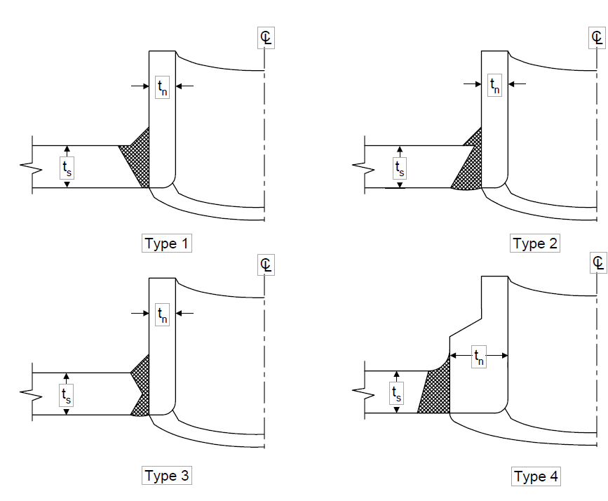
NOTES:
- All nozzle reinforcements and welding details shall be per the ASME Code.
- The minimum permissible radius at the corner of the nozzle inside diameter and shell shall be 1/4 inch.
- Types 1 through 4 are integrally reinforced nozzles.
- Interpretable radiograph results are not readily obtained for the above nozzle attachment welds.
- The ratio of the nozzle to shell thickness (tn/ts) shall not exceed 3.0.
FIGURE 2
PERMISSIBLE BUTT WELDED NOZZLE DETAILS
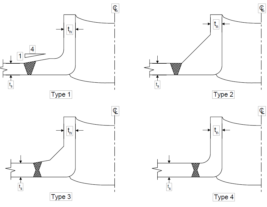
NOTES:
- All nozzle reinforcement and welding details shall be per the ASME Code.
- The minimum permissible radius at the corner of the nozzle inside diameter and shell shall be 1/4 inch.
- Types 1 through 4 are integrally reinforced nozzles.
- Interpretable radiograph results are readily obtained for the above nozzle attachment welds.
© 2026 Inflection Point Engineering, LLC. All rights reserved. The content of this page — including calculation methods, reference data, written analysis, interactive tools, and source code — is the intellectual property of Inflection Point Engineering, LLC and is protected under applicable copyright, trademark, and trade secret laws. Unauthorized reproduction, redistribution, modification, or derivative use in whole or in part is prohibited without prior written consent.
Disclaimer. This material is provided for informational and educational purposes only and does not constitute professional engineering advice. Calculations, reference data, and methodologies are based on published standards and accepted engineering practice but are not a substitute for engineering judgment, site-specific analysis, or review by a licensed Professional Engineer. Inflection Point Engineering, LLC makes no warranties, express or implied, regarding the accuracy, completeness, or fitness for a particular purpose of any content presented here, and shall not be liable for any direct, indirect, incidental, or consequential damages arising from its use. Users assume all risk associated with applying this content to real-world design, operations, or decisions.
© 2026 Inflection Point Engineering, LLC. All rights reserved.