 Section 8 — Heat Transfer Equipment
TEMA Shell and Tube Heat Exchangers for Non-Process Services
IPE Engineering Practice IPE-EP-8-1-2
Document number: IPE-EP-8-1-2 · Section: 8 — Heat Transfer Equipment
1.0
1.1
1.2
1.3
1.4
1.5
2.0
SCOPE
This Practice governs the requirements for the materials, design, fabrication, inspection, testing and preparation for shipment that are unique to the design of shell and tube heat exchangers for non–process services and must be used in conjunction with EP 7–1–2. EP 7–1–2 covers requirements for pressure vessels in non–process services constructed per the ASME Code, Section VIII, Division 1.
This Practice is a purchase specification when accompanied by the herein referenced IPE
Engineering Practices and the completed Data Sheet of EP 8–1–1 DS required by this Practice.
Any deviation from this Practice, or Practices referenced herein, must be approved by the procedure described in EP 1–1–3.
An asterisk (*) indicates that a design by the Owner or Owner’s Engineer is required, or that additional information is furnished by the Purchaser.
A revision bar indicates all changes made to this Revision.
REFERENCES
The latest edition of the following standards and publications are referred to herein.
STANDARDS AND PUBLICATIONS
| IPE Engineering Practices |
|---|
| EP 1–1–3 Deviations to IPE Engineering Practices EP 5–1–2 Piping Layout EP 7–1–2 Pressure Vessels for Non–Process Services EP 7–1–4 Supplemental Requirements for Pressure Vessels EP 7–1–5 Welding Requirements for Pressure Vessels EP 8–1–1 DS TEMA Shell and Tube Heat Exchangers Data Sheet EP 8–1–8 Tube–to–Tubesheet Joints EP 8–1–9 Tube Material and Selection EP 10–3–4 Protective Coatings for Heat Exchangers EP 10–3–5 Cathodic Protection for Heat Exchangers “Anode” Installation |
| ASME Code |
| Sec VIII Pressure Vessels, Division I |
| TEMA |
| Standards of Tubular Exchanger Manufacturers Association |
DEFINITIONS
- Contractor – Company or business that agrees to furnish materials or perform specified services at a specified price and/or rate to the Owner.
- Effective Surface Area – This shall be taken to be the outside surface of tubes based on the length of tubes measured between the inner faces of the tubesheets. For U–Tube exchangers, the exposed surface at the U–bend portion may be included provided shell nozzle location is beyond U–bends and velocity of flowing fluid makes this surface effective.
- Inspector – A Inflection Point Engineering, LLC appointed engineer or inspector.
- Manufacturer – The recipient of a direct or indirect purchase order for materials and/or equipment. In this context, a direct order is one issued to a Manufacturer by a Contractor or the Owner. An indirect order is one issued to a Manufacturer by a vendor (recipient of a direct order) for materials, fabricated components, or subassemblies.
- Owner – IPE Engineering Company.
- Owner’s Engineer – A IPE Engineering Company appointed engineer.
- Purchaser – The party placing a direct purchase order. The Purchaser is the Owner’s designated representative.
DATA SHEET, DOCUMENTATION AND PURCHASING REQUIREMENTS
- Documentation and spare parts requirements for shell and tube heat exchangers in non– process services shall be in accordance with EP 7–1–2 and EP 7–1–4.
- The Data Sheet per EP 8–1–1 DS shall be used.
MATERIALS
- Material requirements for shell and tube heat exchangers shall be in accordance with EP 7–1–2 and the additional requirements of this Practice. Tube material and selection for shell and tube heat exchangers shall be in accordance with EP 8–1–9.
- When the tube material is selected to resist corrosion from the shellside fluid, all other tube bundle components, such as tubesheets, baffles, tie rods and spacers shall be of similar corrosion resistance to, and compatible with, the tube material. Baffle material shall be compatible with the shell material to prevent galvanic corrosion.
DESIGN
- General
- Design requirements for shell and tube heat exchangers shall be used in accordance with EP 7–1–2 and the additional requirements of this practice.
- TEMA Class “C” shall be used as minimum design requirements.
- (*) Unless otherwise specified or approved by the Owner’s Engineer, exchangers shall be designed with the TEMA type A front head.
- (*) The use of fixed tubesheet exchanger designs shall be approved by the Owner’s Engineer.
- The Manufacturer shall be responsible for the mechanical and thermal design.
- All common components such as tubes, tubesheets and floating head assemblies shall be designed for the most severe combination of pressure and temperature conditions. Due consideration shall be given to vacuum acting adjacent to a pressurized chamber.
- Fouling factors given on the Data Sheet of EP 8–1–1 DS are net. Tube side values shall be increased by the ratio of outside to inside surface areas when sizing the heat exchanger.
- (*) The minimum tubeside velocity for cooling water shall be 5 ft/s at the mean temperature. If this requirement conflicts with the allowable pressure drop, an alternate proposal shall indicate the pressure drop necessary to satisfy this requirement. Additionally, if the 5 ft/s minimum velocity requires an increase in water flowrate, the Manufacturer shall notify the Owner’s Engineer in writing.
- Tube metal exposed to cooling water shall be kept below 140ºF to prevent scale deposit of inorganic compounds on the heat transfer surface.
- The maximum tubeside velocity shall be 8 ft/s when water carries solids and shall not exceed 10 ft/s when water is clean and without solids.
- Differential pressure designs are not permitted.
- Calculated pressure drops shall include entrance and exit losses.
- Bundles
- (*) Exchangers shall have removable bundles with a square or rotated square tube layout, unless otherwise approved by the Owner’s Engineer. Bundles for fixed tubesheet exchanger designs shall have triangular tube layout.
- (*) The maximum bundle length for removable bundles shall be 20 feet, unless approved by the Owner’s Engineer.
- Tubesheets
- (*) Threaded bolt holes are not permitted in tubesheets, unless approved by the Owner’s Engineer.
- The difference between the operating temperature of the shell side and tubeside, across the tubesheet, shall be limited to 300 ºF to prevent excessive tubesheet distortion.
- Tube hole tolerances shall be in accordance with EP 8–1–8.
- Tubes
Tube design, material and selection requirements shall be in accordance with EP 8–1–9.
- Baffles and Sealing Devices
- (*) Two pass shell designs are not permitted, unless otherwise approved by the Owner’s Engineer.
- (*) Cross baffles shall be vertically cut unless approved by the Owner’s Engineer.
- Sharp corners at tube holes and on the periphery of exchanger cross baffles and support plates shall be broken (chamfered). All burrs shall be removed from both sides of the tube holes.
- (*) The thickness of transverse baffles shall be in accordance with TEMA. The transverse baffle nearest the floating end, if vertically cut, shall be thick enough to support the floating end, with a minimum thickness of 1/2 inch, unless approved by the Owner’s Engineer.
- All TEMA Type “S” and “T” exchangers shall have a floating head support plate located 2 inches from the shell girth flange face.
- Pressure Boundary Components
- General
Design requirements for pressure boundary components for shell and tube heat exchangers shall be in accordance with EP 7–1–2 and the additional requirements of this Practice.
- Flanged Joints (Girth Flanges)
- The design metal temperature for the bolting for girth flanges abutting the tubesheet shall be the higher of the specified tube or shell side design temperatures.
- (*) The shell cover, channel and channel cover shall be attached with through–bolted flanged joints, unless approved by the Owner’s Engineer.
- Shells, Channels and Covers
- (*) The maximum shell diameter for removable bundle exchangers is 24 inches. Larger shells may be used if approved by the Owner’s Engineer.
- (*) Protective coatings and anodes, in accordance with EP 10–3–4 and EP 10–3–5, respectively, shall be provided for channels in cooling water service, or when specified on the Data Sheet per EP 8–1–1 DS.
- Pass Partition Plates
(*) Unless otherwise specified by the Owner’s Engineer, pass partition plate thickness shall be in accordance with TEMA Paragraph RCB–9.131. Pass partition plates for channels and floating heads in water service shall have a 1/2 inch minimum thickness.
- Floating Head Assemblies
- Split ring floating head designs that use a spacer ring are strictly prohibited.
- Floating head assemblies shall not be designed for differential pressure.
- Protective coatings and/or anodes, in accordance with EP 10–3–4 and EP 10–3–5, respectively, shall be provided for floating heads in cooling water service.
- (*) Floating heads shall be designed per Figure 1–6(d) of Appendix 1 in the ASME Code. Other designs require the approval of the Owner’s Engineer.
- (*) Floating heads, floating head flanges and bolting shall be designed for the most severe design temperature (internal or external). Actual metal temperatures may be used only if calculations for metal temperatures are submitted for review and acceptance by the Owner’s Engineer.
- Nozzles and Other Connections
- Nozzles and nozzle flanges shall be in accordance with EP 7–1–2.
- Chemical cleaning connections, instrument connections, vents and drains, and other connections shall be designed in accordance with EP 7–1–2 and the additional requirements of this Practice.
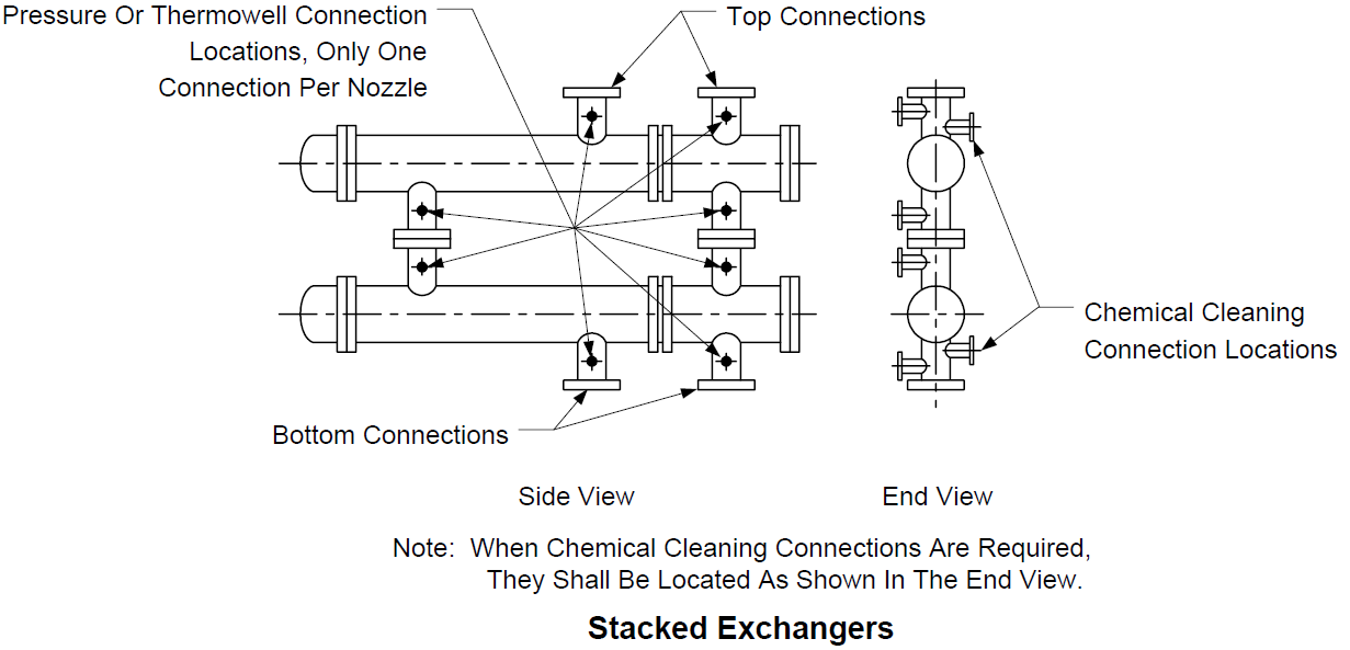
- One instrument connection shall be provided in each nozzles as shown in Figure 1, and shall be in accordance with EP 7–1–2.
- (*) Chemical cleaning connections shall be provided at the inlet and outlet of exchangers in cooling water service, or when specified by the Owner’s Engineer.
- (*) Chemical cleaning connections, when specified, shall be NPS 1–1/2 inch connections for nozzles NPS 4 or NPS 6 inch, and NPS 2 inch connections for nozzles NPS 8 inch or larger.
- (*) Chemical cleaning connections, when specified, shall be located as shown in Figure 1 for exchanger nozzles NPS 4 inch and larger. For nozzles less than NPS 4 inch, chemical cleaning connections shall be installed in the connecting piping per EP 5–1–2.
- (*) Channel vents and drains shall be installed in nozzle necks if the nozzle centerlines are vertical. When chemical cleaning connections are also specified, they can also serve as vents and drains.
- (*) For a floating head bundle design, the shell side vent and drain shall be in the shell cover. For a U–tube design, the shell vent and drain may be eliminated, provided the instrument connections in the shell inlet and outlet nozzles can serve as the vent and drain and when approved by the Owner’s Engineer.
- (*) Unless otherwise specified by the Owner’s Engineer, vents and drains shall be NPS 1 inch minimum. Vents and drain connections shall be in accordance with EP 7–1–2.
- Handling and Lifting Facilities
- Handling and lifting facilities for shell and tube heat exchangers shall be in accordance with EP 7–1–2 and the additional requirements of the Practice.
- Lifting lugs shall be provided on the centerline of all removable exchanger components. When exchanger shells are stacked, two lifting lugs for removable components shall be at 45 degrees from the vertical line on the bottom exchanger.
- (*) Unless otherwise specified, stationary tubesheets in removable bundle exchangers shall be supplied with lifting lugs or tapped holes for eye bolts located radially on the outer edge of the tubesheet to facilitate removal of the tube bundle from the shell. The opening in lifting lugs shall be at least 2 inches in diameter. These lifting facilities are in addition to the tapped holes for pulling eyes required by TEMA.
6.11 Stacking Requirements
Design requirements for the support of stacked exchangers shall be in accordance with EP 7– 1–2.
FABRICATION
- General
Fabrication requirements for shell and tube heat exchangers in non-process services shall be in accordance with EP 7–1–2 and the additional requirements of this Practice.
- Tube Installation
Tube installation, tube–to–tubesheet joint design and fabrication requirements shall be in accordance with EP 8–1–8.
- Welding
Welding shall be in accordance with EP 7–1–2 and EP 7–1–5.
- Heat Treatment
- Heat treatment requirements for shell and tube heat exchangers in non–process services shall be in accordance with EP 7–1–2 and the additional requirements of this Practice.
- Heat treatment requirements for tube end welds and tube U–bends shall be in accordance with EP 8–1–8 and EP 8–1–9, respectively.
INSPECTION AND TESTING
- General
- Inspection and testing requirements for shell and tube heat exchangers shall be in accordance with EP 7–1–2, EP 8–1–8 and the additional requirements of this Practice.
- (*) The insertion and withdrawal of removable tube bundles shall be witnessed and accepted by the Inspector. A vibration device shall not be used as an aid to bundle insertion or withdrawal.
- Hydrostatic Testing
- Hydrostatic testing requirements for shell and tube heat exchangers shall be in accordance with EP 7–1–2 and the additional requirements of this Practice.
- Each heat exchanger shall be hydrotested on the shellside and the tubeside separately. The side not being hydrotested shall be exposed to the atmosphere.
- Stacked exchangers shall be hydrostatically tested in the stacked position to assure that all intermediate nozzles are satisfactorily aligned.
9.0 Figures
© 2026 Inflection Point Engineering, LLC. All rights reserved. The content of this page — including calculation methods, reference data, written analysis, interactive tools, and source code — is the intellectual property of Inflection Point Engineering, LLC and is protected under applicable copyright, trademark, and trade secret laws. Unauthorized reproduction, redistribution, modification, or derivative use in whole or in part is prohibited without prior written consent.
Disclaimer. This material is provided for informational and educational purposes only and does not constitute professional engineering advice. Calculations, reference data, and methodologies are based on published standards and accepted engineering practice but are not a substitute for engineering judgment, site-specific analysis, or review by a licensed Professional Engineer. Inflection Point Engineering, LLC makes no warranties, express or implied, regarding the accuracy, completeness, or fitness for a particular purpose of any content presented here, and shall not be liable for any direct, indirect, incidental, or consequential damages arising from its use. Users assume all risk associated with applying this content to real-world design, operations, or decisions.
© 2026 Inflection Point Engineering, LLC. All rights reserved.