 Section 8 — Heat Transfer Equipment
TEMA Shell and Tube Heat Exchangers
IPE Engineering Practice IPE-EP-8-1-1
Document number: IPE-EP-8-1-1 · Section: 8 — Heat Transfer Equipment
SCOPE
- This Practice governs the requirements for the materials, design, fabrication, inspection, testing, and preparation for shipment of shell and tube heat exchangers for use in refining process services.
- This Practice, in general, governs the requirements that are unique to the design of shell and tube heat exchangers and must be used in conjunction with EP 7–1–1 which covers requirements for pressure vessels constructed per the ASME Code, Section VIII, Division 1.
- (*) EP 8–1–2 may be used in place of this Practice when the application meets the scope of EP 8–1–2 or when approved by the Owner’s Engineer.
- This Practice is a purchase specification when accompanied by the herein referenced IPE Engineering Practices and the completed Data Sheet of EP 8–1–1 DS required by this Practice.
- Any deviation from this Practice, or Practices referenced herein, must be approved by the procedure described in EP 1–1–3.
- An asterisk (*) indicates that a decision by the Owner or Owner’s Engineer is required, or that additional information is furnished by the Purchaser.
- A revision bar indicates all changes made to this Revision.
2.0 REFERENCES
The latest edition of the following standards and publications are referred to herein.
STANDARDS AND PUBLICATIONS
| IPE Engineering Practices | IPE Engineering Practices |
|---|---|
| EP 1–1–3 | Deviations to IPE Engineering Practices |
| EP 3–7–1 | Pressure Relieving Systems |
| EP 5–1–2 | Piping Layout |
| EP 7–1–1 | Pressure Vessels |
| EP 7–1–3 | Heavy Wall and Special Service Pressure Vessels |
| EP 7–1–4 | Supplemental Requirements for Pressure Vessels |
| EP 7–1–5 | Welding Requirements for Pressure Vessels |
| EP 7–1–6 | Metal Lining and Cladding |
| EP 7–1–7 | Pressure Vessel Details |
| EP 8–1–1 DS | TEMA Shell and Tube Heat Exchangers Data Sheet |
| EP 8–1–2 | TEMA Shell and Tube Heat Exchangers for Non–Process Services |
| EP 8–1–8 | Tube–to–Tubesheet Joints |
| EP 8–1–9 | Tube Material and Selection |
STANDARDS AND PUBLICATIONS (CONT.)
| IPE Engineering Practices (Cont’d) |
|---|
| EP 10–2–1 Material Requirements for Aggressive Environmental Services EP 10–3–4 Protective Coatings for Heat Exchangers EP 10–3–5 Cathodic Protection for Heat Exchangers “Anode” Installation EP 11–3–1 Insulation Design EP 11–3–3 Insulation Application – Vessels and Equipment |
| API Publications |
| Std 660 Shell–and–Tube Heat Exchanger for General Refinery Services Publ 941 Steels for Hydrogen Service at Elevated Temperatures and Pressures in Petroleum Refineries and Petrochemical Plants |
| ASME Code |
| Sec I Pressure Vessels Sec VIIIPressure Vessels, Division I Sec VIIIPressure Vessels, Division II |
| Publications |
| Chenoweth, J.M. and Kistler, R.S., “Tube Vibrations in Shell–and–Tube Heat Exchangers,” HTRI Technical Report, No. STV-1, April, 1978. |
| TEMA |
| Standards of Tubular Exchanger Manufacturers Association |
DEFINITIONS
- Aggressive Environmental Service (AES) – Process services which result in material degradation such as cracking, scaling, blistering, and severe pitting and/or corrosion. Examples of such services are hydrogen service, wet hydrogen sulfide, cyanides, caustic, amine, and hydrofluoric acid. AES process fluid are defined in EP 10–2–1.
- Contractor – Company or business that agrees to furnish materials or perform specified services at a specified price and/or rate to the Owner.
- Effective Surface Area – This shall be taken to be the outside surface of tubes based on the length of tubes measured between the inner faces of the tubesheets. For U–Tube exchangers, the exposed surface at the U–bend portion may be included provided the shell nozzle location is beyond the U–bends and the velocity of the flowing fluid makes this surface effective.
- Hydrogen Rich Service – A service defined as a combination of hydrogen partial pressure and temperature at or below the curve for carbon steel per Figure 1 of API Publication 941, latest edition, and with a hydrogen partial pressure greater than 100 psia.
- Hydrogen Service – A service defined as a combination of hydrogen partial pressure and temperature above the curve for carbon steel per Figure 1 of API Publication 941, latest edition.
- Inspector – A Inflection Point Engineering, LLC appointed engineer or inspector.
- Manufacturer – The recipient of a direct or indirect purchase order for materials and/or equipment. In this context, a direct order is one issued to a Manufacturer by a Contractor or the Owner. An indirect order is one issued to a Manufacturer by a vendor (recipient of a direct order) for materials, fabricated components, or subassemblies.
- Owner – Inflection Point Engineering, LLC.
- Owner’s Engineer – A Inflection Point Engineering, LLC appointed engineer.
- Purchaser – The party placing a direct purchase order. The Purchaser is the Owner’s designated representative.
- Rotatable Bundle – A tube bundle designed to be rotated 180º without affecting shell or tubeside flow patterns, heat transfer or pressure drop.
DATA SHEET, DOCUMENTATION AND PURCHASING REQUIREMENTS
- Data Sheet, per EP 8–1–1 DS, documentation and spare parts requirements for shell and tube heat exchangers shall be in accordance with EP 7–1–1, EP 7–1–4 and the additional requirements of this Practice.
- Proposals for designs that are not fully defined by the nomenclature in TEMA such as designs using TEMA type D heads and heads using diaphragms or lip seals, shall be accompanied by drawings sufficient to describe the details of construction.
MATERIALS
- Material requirements for shell and tube heat exchangers shall be in accordance with EP 7–1–1 and the additional requirements of this Practice. When AES is checked “yes” on the Data Sheet from EP 8–1–1 DS, the additional material requirements of EP 10–2–1 and EP 10–2–3 shall be met. Tube material and selection shall be in accordance with EP 8–1–9.
- When the tube material is selected to resist corrosion from the shellside fluid, all other tube bundle components, such as tubesheets, baffles, tie rods and spacers shall be of similar corrosion resistance to, and compatible with, the tube material. Baffle material shall be compatible with the shell material to prevent galvanic corrosion.
- (*) Clad or overlayed tubesheets are acceptable when approved by the Owner’s Engineer and shall be in accordance with EP 7–1–6.
- Tubesheet plates greater than 4 inches thick, shall be inspected prior to drilling, using ultrasonic examination in accordance with SA-435, supplementary requirement S1.
- When exposed to cyanides, all internal bolting (except for tie rods) shall be stainless steel (type
304) (A193 B8c Class 1).
DESIGN
- General
- Design requirements for shell and tube heat exchangers shall be in accordance with EP 7–1–1 and the additional requirements of this Practice.
- API 660 and TEMA Class R shall be used as the minimum design requirements. Where conflicts arise, the more stringent requirements shall apply.
- (*) Unless otherwise specified or approved by the Owner’s Engineer, exchangers shall be designed with the TEMA type A front head. TEMA type D heads shall be provided when the tubeside design pressure exceeds 2200 psig. Consideration should be given to the use of diaphragms or lip seals for high pressure, difficult to seal applications.
- (*) The use of two pass shell designs, TEMA type F, shall be approved by the Owner’s Engineer. Due consideration must be given to the economic impact of handling and maintaining the lamiflex seals versus the capital cost savings associated with the F shell design. The application of TEMA type F shells shall be limited to 250ºF maximum temperature difference and 5 psi maximum pressure difference across a single shell.
- (*) Approval from the Owner’s Engineer is required to quote the following designs.
- Single pass tube side design with an internal expansion joint
- Exchangers with a wall thickness 2 inches or greater (high pressure and/or heavy wall exchangers) per EP 7–1–3.
- Differential pressure designs
- Fixed tubesheet exchanger designs
- Exchangers greater than 48 inches in diameter
- (*) Exchangers with the high pressure side having an appreciably greater design pressure than the low pressure side shall have nozzles for pressure relief devices as stipulated in EP 3–7–1, when specified by the Owner’s Engineer on the Data Sheet of EP 8–1–1 DS.
- The Manufacturer shall be responsible for the mechanical and thermal design.
- All common components such as tubes, tubesheets and floating head assemblies shall be designed for the most severe combination of pressure and temperature conditions. Due consideration shall be given to vacuum acting adjacent to a pressurized chamber.
- Fouling factors given on the Data Sheet of EP 8–1–1 DS are net. Tube side values shall be increased by the ratio of outside to inside surface areas when sizing the heat exchanger.
- (*) Exchanger bundles shall be checked to assure that a vibration problem does not exist at the inlet, between baffles, and at the outlet. Upon request, calculations shall be submitted to the Owner’s Engineer for review. As a minimum, the criteria found in Table 1 shall be satisfied.
- (*) The minimum tubeside velocity for cooling water shall be 5 ft/s at the mean temperature. If this requirement conflicts with the allowable pressure drop, an alternate proposal shall indicate the pressure drop necessary to satisfy this requirement. Additionally, if the 5 ft/s minimum velocity requires an increase in water flowrate, the Manufacturer shall notify the Owner’s Engineer in writing.
- Tube metal exposed to cooling water shall be kept below 140ºF to prevent scale deposit of inorganic compounds on the heat transfer surface.
- The minimum tubeside velocity for hydrocarbon liquids shall be 3 ft/s. The velocity shall be calculated at the mean temperature.
- The maximum tubeside velocity shall be 8 ft/s when water carries solids and shall not exceed 10 ft/s when water is clean and without solids.
- The tubeside velocity in slurry oil service shall be between 4.5 and 7.0 ft/sec.
- The maximum tubeside velocity for an amine solution shall be 3 ft/s to minimize erosion/corrosion effects.
- The net unrestricted flow area at the following points shall not be less than the open area of the shell inlet nozzle or nozzles:
- From inlet nozzle to impingement device
- Off the impingement device
- Into the tube field
- (*) Differential pressure designs are not permitted without approval by the Owner’s Engineer. When approved, the maximum differential pressure for hydrostatic testing shall be stamped on the nameplate.
- Calculated pressure drops shall include the nozzle entrance and exit losses.
- The effective surface for U-bend bundles may include the U-tube area provided the shell nozzle extends beyond the bundle.
- (*) For pull through floating head designs, TEMA type T, a removable shell cover shall be provided, unless otherwise specified by the Owner’s Engineer.
- For vertical exchangers where the shell side liquid is flowing upwards, the Manufacturer shall provide calculations verifying that localized boiling will not occur near the face of the upper tubesheet.
- Bundles
- (*) Exchangers shall have removable bundles with a square or rotated square tube layout, unless otherwise approved by the Owner’s Engineer. Bundles for fixed tubesheet exchanger designs shall have triangular tube layout.
- Identical removable bundle type exchangers shall have interchangeable bundles.
- When specified on the Data Sheet of EP 8–1–1 DS, removable bundles shall be designed for 180º rotation, however, an impingement plate shall not be installed opposite the outlet nozzle.
- (*) When specified by the Owner’s Engineer, horizontal bundles shall have notched tube spacers as shown in Figure 1.
- For removable bundles in excess of 6 tons, skid bars shall be provided as shown in Figure 2.
- The floating head of kettle type reboilers or the end support plate of U–bend type kettle reboilers shall be positioned within the shell by a rigid structure designed to center the bundle as it is inserted and to hold it in its normal position during shipment and operation.
- (*) The maximum bundle length shall be 20 feet for removable bundles, unless approved by the Owner’s Engineer.
- Tubesheets
- (*) Threaded bolt holes are not permitted in tubesheets, unless approved by the Owner’s Engineer.
- Cladding and overlaying requirements for tubesheets shall be in accordance with EP 7–1–6.
- Corners formed in tubesheets where gasket grooves intersect, shall be shaped to match the gasket with an approximate corner radius of 1/2 inch.
- Tube hole tolerances shall be in accordance with EP 8–1–8.
- For tubesheet designs other than the flexible type (as described in paragraph 6.13.5.3), the difference between the operating temperatures of the shellside and tubeside, across the tubesheet, shall be limited to 300 ºF to prevent excessive tubesheet distortion.
- A 1/8 inch deep scribe line shall be provided in the outer face of the stationary and floating tubesheets at the 3 and 9 o’clock positions to insure correct alignment when matched with similar scribe lines on the channel, shell, and floating head.
- The design of a double tubesheet shall permit pressure testing of the tube–to–tubesheet joints in each tubesheet. Additionally, double tubesheet designs shall not have bolting that spans the tubesheets.
- Tubes
Tube design, material, and selection requirements shall be in accordance with EP 8–1–9.
- Baffles and Sealing Devices
- Two pass TEMA Type F shell designs may be quoted as alternates to single pass shells, but their application shall be limited to 250 ºF maximum temperature difference and 5 psi maximum pressure difference across the single shell.
- (*) TEMA Type F shells with removable bundles, the longitudinal baffle shall be continuously welded on both sides to the stationary tubesheet, and sealed against the shell walls by labyrinth type multiple layer stainless steel thin leaved seals. Longitudinal baffles may be recess gasketed to the stationary tubesheet,if specified by the Owner’s Engineer.
- For TEMA Type F shells with fixed tubesheet bundles, the longitudinal baffles shall be continuously welded from both sides to the front tubesheet and to the shell walls.
- The maximum unsupported tube length shall be 80% of the recommended values given in TEMA Table RCB–4.52.
- (*) Cross baffles shall be vertically cut unless approved by the Owner’s Engineer.
- Sharp corners at tube holes and on the periphery of exchanger cross baffles and support plates shall be broken (chamfered). All burrs shall be removed from both sides of the tube holes. This applies to all baffles on new or retubed bundles.
- Close fit baffles shall not be used because they may cause scoring of the tubes. However, baffle and support plate holes shall be drilled and reamed in accordance with TEMA RCB–4.2 close fit requirements for the following:
- units with water on the shellside
- titanium tube bundles
- unsupported tube lengths exceeding 36 inches
- units where vibration is a concern
- units where the average tube wall thickness is 0.065 inch (16 BWG) or thinner
- (*) when specified by the Owner’s Engineer
- Seal bars and skid bars shall be welded to every baffle with full fillet welds to prevent bypassing. Two welds shall be made on opposite corners, 180 degrees apart. Seal bars and skid bars may be welded to every other baffle provided the baffle spacing is less than 12 inches (maximum unsupported tube length less than 24 inches).
- The minimum thickness of transverse baffles shall be in accordance with Table 4.
- The transverse baffle nearest the floating end, if vertically cut, shall be thick enough to support the floating end, with a minimum thickness of 1/2 inch.
- All TEMA Type “S” and “T” exchangers shall have a floating head support plate located 4 inches to 6 inches from the inside face of the floating tubesheet.
- (*) Unless otherwise specified on the Data Sheet of EP 8–1–1 DS, by–pass seal strips shall be provided as follows:
- Seal strips are required for all exchangers when the radial distance between the outermost tubes and the inside diameter of the shell exceeds 3/4 inch. Seal strips are not required for kettle type reboilers.
- Exchangers with vertically cut baffles shall have seal strips installed to seal by–pass areas caused by the omission of tubes to provide adequate entrance and exit areas.
- Seal strips or dummy tubes are required to block pass partition by–pass lanes when these lanes are parallel to the shellside flow.
- Seal strips shall be 3/8 inch thick minimum and shall extend from the first to the last segmental baffle.
- One pair of seal strips or dummy tubes shall be provided for each 5 tube rows between baffle cuts. Minor adjustments may be made to suit actual tube layout.
- Baffle ears are required on vertically cut baffles to block longitudinal by–pass areas caused by the omission of tubes to provide adequate entrance and exit velocities.
- Pressure Boundary Components
- General
Design requirements for pressure boundary components for shell and tube heat exchangers shall be in accordance with EP 7–1–1 and the additional requirements of this Practice.
- Flanged Joints (Girth Flanges)
- The design metal temperature for the bolting for girth flanges abutting the tubesheet shall be the higher of the specified tube or shellside design temperatures.
- (*) The shell cover, channel, and channel cover shall be attached with through–bolted flanged joints, unless approved by the Owner’s Engineer.
- The pass partition rib area shall be included as gasket seating area when determining the required bolt loads in the design of flanges per Appendix 2 of the ASME Code.
- A 1/8 inch deep scribe line shall be provided on the outer face of all flanges at the 3 and 9 o’clock positions to insure correct alignment when matched with similar scribe lines on tubesheets, shell, channel, and floating head.
- Shells, Channels and Covers
- (*) To facilitate bundle handling, the maximum shell diameters for removable bundle exchangers normally permitted are shown in Table 2. Larger shells may be used if approved by the Owner’s Engineer.
- (*) Anodes, in accordance with EP 10–3–4, shall be provided for channels in cooling water service, or when specified on the Data Sheet EP 8–1–1 DS. Protective coatings, in accordance with EP 10–3–5, shall be provided for channels in cooling water service when specified by the Owner’s Engineer, or when specified on the Data Sheet EP 8–1–1 DS.
- (*) When a rotatable bundle is specified, the channel shall be designed to allow bundle rotation without affecting the attached pipe.
- A radial clearance of at least 3/16 inch shall be provided between bolted–on shell covers and TEMA “S” type floating heads and split rings.
- Pass Partition Plates
- Pass partition plates in channels and floating heads shall be full length welded from both sides. In Hydrogen Service and Hydrogen Rich Service, full penetration welds are required.
- The minimum pass partition plate thickness shall be as shown in Table 3.
- Pass partition plates for channels and floating heads in water service shall have a 1/2 inch minimum thickness.
- (*) The Manufacturer shall submit a design to be approved by the Owner’s Engineer for the channel pass partition plate which incorporates features to minimize thermal stress when all of the following conditions apply:
- Temperature drop or rise of the tubeside fluid across any channel partition plate is greater than 250 ºF.
- Tubeside design pressure is greater than 500 psig.
- Hydrogen Service or Hydrogen Rich Service.
- Exchanger inside diameter is greater than 24 inches.
- Floating Head Assemblies
- (*) Acceptable floating head assembly designs are to be per Figure 3A, Figure 3B, and Figure 3C of this Practice. Designs other than these are to be approved by the Owner’s Engineer.
- Split ring floating head designs that use a spacer or a split key ring are strictly prohibited.
- When the tubeside operating pressure exceeds the shellside pressure by 250 psi or more and the diameter is over 36 inches, a split ring floating head must be of the chevron or dove tail design as shown in Figure 3A.
- (*) Floating head assemblies shall not be designed for differential pressure unless approved by the Owner’s Engineer.
- (*) Protective coatings and/or anodes, in accordance with EP 10–3–4 and EP 10–3–5, respectively, shall be provided for floating heads in cooling water service, or when specified on the Data Sheet per EP 8–1–1 DS.
- (*) Floating heads, floating head flanges and split rings shall be designed for design conditions on each side with the other side at atmospheric conditions, unless approved by Owner’s Engineer. When one of the sides is also designed for vacuum conditions, the floating head assembly must be designed to handle the equivalent pressure. For example, if the shellside design pressure is 150 psi and the tubeside is to be designed for full vacuum, the floating head assembly must be designed to handle an external pressure of 165 psi.
- (*) Floating heads shall be designed per Figure 1–6(d) of Appendix 1 in the ASME Code. Other designs require the approval of the Owner’s Engineer.
- Nozzles and Other Connections
- Nozzles and nozzle flanges shall be in accordance with EP 7–1–1.
- Chemical cleaning connections, instrument connections, vents and drains, and other connections shall be designed in accordance with EP 7–1–1 and the additional requirements of this Practice.
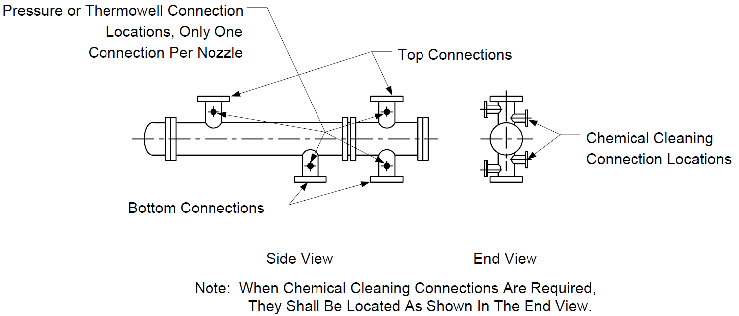
- One NPS 1 inch instrument connection shall be provided in each nozzle as shown in Figure 4, and shall be in accordance with EP 7–1–1.
- Chemical cleaning connections shall be provided at the inlet and outlet of exchangers in cooling water service, or when specified by the Owner’s Engineer.
- (*) Chemical cleaning connections, when specified, shall be NPS 1–1/2 inch connections for nozzles NPS 4 or NPS 6 inch, and NPS 2 inch connections for nozzles NPS 8 inch or larger.
- (*) Chemical cleaning connections, when specified, shall be located as shown in Figure 4 for exchanger nozzles NPS 4 inch and larger. For nozzles less than NPS 4 inch, chemical cleaning connections shall be installed in the connecting piping per EP 5–1–2.
- For horizontal exchangers, channel vents and drains shall be installed in nozzle necks if the nozzle centerlines are vertical. When chemical cleaning connections are also specified, they can also serve as vents and drains.
- (*) For horizontal exchangers with a floating head bundle design, the shellside vent and drain shall be in the shell cover. For a U–tube design, the shell vent and drain shall be in the shell or may be eliminated provided the instrument connections in the shell inlet and outlet nozzles can serve as the vent and drain and when approved by the Owner’s Engineer. Elimination of the vent and drain in this manner can reduce the potential for flange leakage and may reduce costs. Flange leakage is of concern, particularly in Hydrogen Service where flanges are typically more difficult to seal.
- For vertical exchangers, a vent for each tubeside pass shall be supplied in the channel cover. For vertical exchangers with one tubeside pass, a drain shall be supplied in the lower tubeside nozzle.
- (*) For vertical exchangers, a shellside vent shall be supplied in the tubesheet. Detailed drawings of the proposed tubesheet vent shall be supplied for approval by the Owner’s Engineer. A shellside drain shall be supplied in the bottom head.
- (*) Unless otherwise specified by the Owner’s Engineer, vents and drains shall be NPS 1 inch minimum. Vents and drain connections shall be in accordance with EP 7–1–1.
- (*) When specified on the EP 8–1–1 DS, for fixed tubesheet exchangers less than 30 inches in diameter, NPS 4 inch inspection nozzles shall be provided in the shell on the downstream side of the inlet and outlet baffles. For fixed tubesheet exchangers, 30 inches in diameter and greater, NPS 8 inch inspection nozzles shall be provided in the same locations.
- Handling and Lifting Facilities
- Handling and lifting facilities for shell and tube heat exchangers shall be in accordance with EP 7–1–1 and the additional requirements of this Practice.
- Lifting lugs shall be provided on the centerline of all removable exchanger components. When exchanger shells are stacked, two lifting lugs for removable components shall be at 45º from the vertical center line on the bottom exchanger.
- (*) Unless otherwise specified, stationary tubesheets in removable bundle exchangers shall be supplied with lifting lugs or tapped holes for eye bolts located radially on the outer edge of the tubesheet to facilitate removal of the tube bundle from the shell. The opening in lifting lugs shall be at least 2 inches in diameter. When bundles are designed for 180º rotation, lifting lugs or tapped holes shall be provided both top and bottom. These lifting facilities are in addition to the tapped holes for pulling eyes required by TEMA.
- (*) Davits, or other means to remove shell covers and/or floating heads, shall be provided when specified by the Owner’s Engineer in applications where accessibility by a crane is limited. Davits shall be designed in accordance with EP 7–1–7.
- Stacking Requirements
Design requirements for the support of stacked exchangers shall be in accordance with EP 7– 1–1.
- Insulation Supports
(*) Insulation supports per Figure 13 of EP 11–3–3 shall be provided on shell covers and channel covers, when specified by the Owner’s Engineer.
- Special Designs
- Shellside Expansion Joints
- Flanged and flued type expansion joints are preferred over the bellows type and shall be designed in accordance with Appendix CC of the ASME Code.
- (*) Bellows type expansion joints shall be designed in accordance with Appendix 26 of the ASME Code. Their use requires the approval of the Owner’s Engineer.
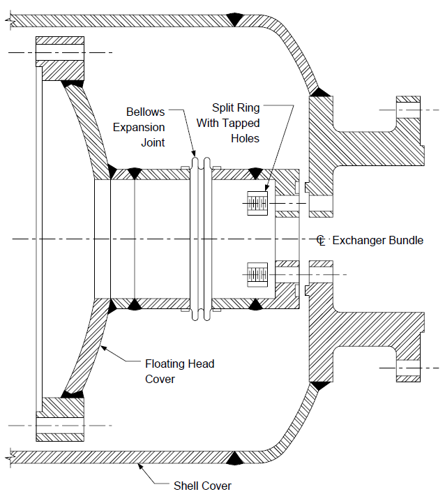
- Single Pass Tube Side Design with an Internal Expansion Joint
- The expansion joint design shall be in accordance with Figure 5 and EP 5–4–1.
- The shell cover nozzle flange shall be a through–bolted design.
- The floating head–to–shell cover nozzle connection shall be through–bolted into the tapped segmental ring. The segmental ring with studs in place shall be removable through the shell cover nozzle.
- The floating head cover–to–shell cover connection shall be the tongue and groove type with the tongue in the shell cover.
- The bellows–type expansion joint shall be designed to withstand the full shell and tube side hydrostatic tests, acting separately.
- (*) When specified on the Data Sheet of EP 8–1–1 DS, the Manufacturer shall supply an apparatus to facilitate tube side hydrostatic testing with the shell cover removed.
- For kettle type reboilers:
- (*) Unless otherwise specified by the Owner’s Engineer, a weir plate shall be located directly behind the tube bundle. The weir plate shall be continuously welded to the shell inside diameter, shall contain no drain holes and shall be of sufficient height to flood the top row of tubes with a minimum of 2 inches of process fluid during normal operation.
- Provide riding rails (or tracks) that are fully seal welded to the sides of the shell to support and guide the tube bundle. Also, provide a “hold” angle iron above the tube bundle to keep the bundle in place during shipment and handling. It is to be located directly above and
close to the floating head flanges (TEMA Type “T”) or the full diameter, support plate when U–bend construction is used.
- Large Diameter Exchangers (50” diameter and over):
- (*) Written approval from Owner’s Engineer is required.
- (*) Large diameter exchangers shall be quoted with normal bolted flanges, unless noted otherwise on the data sheet. If welded channels are specified on the data sheet, the channels are to have adequate depth and sufficient manways to facilitiate tubeside cleaning.
- All exchangers greater than 60 inches ID, regardless of whether they have bolted or welded channel sections, shall have inspection manways. Inspection manways shall be located in the top channel of vertical exchangers and shall be a minimum of 20 inches in diameter.
- Special flange design procedures for bolt spacing and flange thickness are to be in accordance with EP 7–1–1.
- For Sulfur Condensers:
- (*) Unless otherwise approved by the Owner’s Engineer, the condensers shall be TEMA type NEN or CEN, and shall meet TEMA Class R requirements.
- The shellside and tubeside shall be in accordance with Section VIII, Division I of the ASME Code.
- The condensers shall be designed with flexible tubesheets. Flexible tubesheet design shall be in accordance with Section I, Part PFT of the ASME Code. The minimum thickness of the tubesheets, including corrosion allowance, shall be 1 inch.
- If horizontal tube bundles are used, the entire unit shall be sloped 1/4 in/ft downward to the outlet channel.
- All tube–to–tubesheet joints shall be grooved, rolled, and strength welded in accordance with EP 8–1–8.
FABRICATION
- General
Fabrication requirements for shell and tube heat exchangers shall be in accordance with EP 7– 1–1 and the additional requirements of this Practice.
- Tube Installation
Tube installation, tube–to–tubesheet joint design and fabrication requirements shall be in accordance with EP 8–1–8.
- Welding
Welding shall be in accordance with EP 7–1–1 and EP 7–1–5.
- Heat Treatment
- Heat treatment requirements for shell and tube heat exchangers shall be in accordance with EP 7–1–1 and the additional requirements of this Practice.
- PWHT is required for all carbon steel and chrome–moly (P1, P3, P4, P5) exchanger channels and floating heads, regardless of thickness, in accordance with EP 7–1–5.
- Heat treatment requirements for tube end welds and tube U–bends shall be in accordance with EP 8–1–8 and EP 8–1–9, respectively.
INSPECTION AND TESTING
- General
- Inspection and testing requirements for shell and tube heat exchangers shall be in accordance with EP 7–1–1, EP 8–1–8 and the additional requirements of this Practice.
- (*) The insertion of removable tube bundles shall be witnessed and accepted by the Inspector. A vibration device shall not be used as an aid to bundle insertion or withdrawal. Complete withdrawal is not required on exchangers with longitudinal baffles.
- (*) Plug tests are required when replacement shells are being fabricated for use with existing bundles. The insertion and withdrawal of the plug shall be witnessed and accepted by the Inspector. A vibration device shall not be used to aid plug insertion or withdrawal.
- Hydrostatic Testing
- Hydrostatic testing requirements for shell and tube heat exchangers shall be in accordance with EP 7–1–1 and the additional requirements of this Practice.
- Each heat exchanger shall be hydrotested on the shellside and the tubeside separately. The side not being hydrotested shall be exposed to atmosphere.
- (*) For heat exchangers designed on the basis of shellside/tubeside pressure differentials for which test pressures must be applied concurrently, hydrotest procedures shall be provided by the Manufacturer for acceptance by the Owner’s Engineer.
- Stacked exchangers shall be hydrostatically tested in the stacked position to assure that all intermediate nozzles are satisfactorily aligned.
- For exchangers with titanium tubes, the hydrostatic test shall be maintained for 24 hours.
9.0 TABLES
TABLE 1 VIBRATION DESIGN CRITERIA
NOTE:
(1) Calculations of these parameters can be found in TEMA or in the HTRI publication “Tube Vibrations in Shell and–Tube Heat Exchangers” (see Section 2.0 for reference)
TABLE 2
MAXIMUM SHELL DIAMETERS WITH REMOVABLE BUNDLES
| Bundle Length | Max. Shell l.D. |
|---|---|
| 16 ft. 20 ft. |
48 inches 42 inches |
TABLE 3
MINIMUM PASS PARTITION PLATE THICKNESS
| Nominal Shell Diameter | Carbon Steel Material | Alloy Material |
|---|---|---|
| Less than 24 inches 24 - 39 inches 40 - 60 inches |
3/8 inch 1/2 inch 5/8 inch |
1/4 inch 3/8 inch 1/2 inch |
TABLE 4
MINIMUM REQUIRED BAFFLE THICKNESSES
| Material | Minimum Thickness |
|---|---|
| Carbon Steel and Low Chrome (9% Chrome or less) | TEMA Table R-4.41, plus a shell side corrosion allowance |
| Austenitic and Duplex Stainless Steels | TEMA Table R-4.41 plus 1/16 inch |
| Titanium | 5/8 inch |
| All other materials | Requires approval of Owner’s Engineer |
10.0 FIGURES
FIGURE 1 NOTCHED TIE ROD SPACER
Tie Rod Spacer
FIGURE 2 SKID BARS
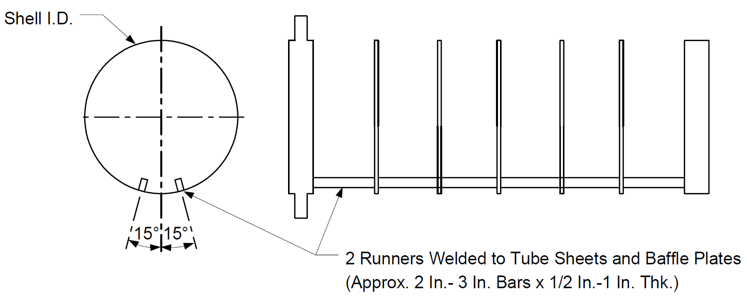
FIGURE 3A
FLOATING HEAD ASSEMBLY DESIGN
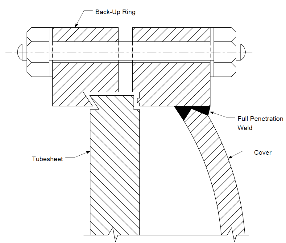
FIGURE 3B
FLOATING HEAD ASSEMBLY DESIGN
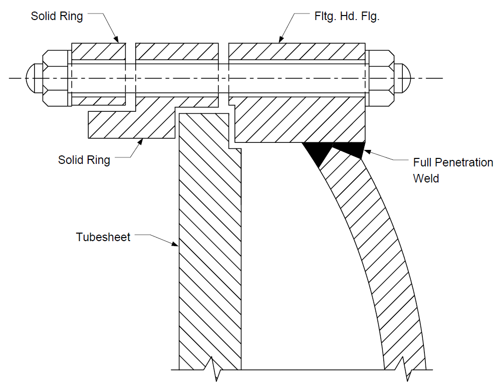
FIGURE 3C
FLOATING HEAD ASSEMBLY DESIGN
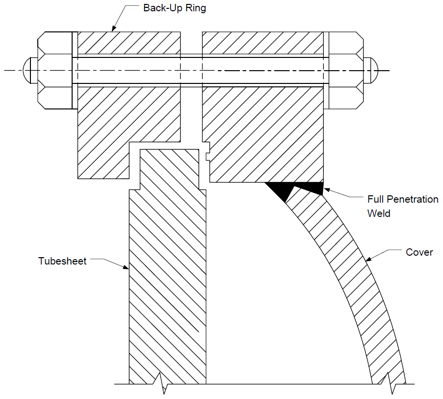
FIGURE 4 CONNECTION LOCATIONS
Single Exchanger
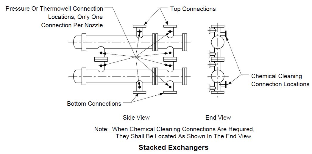
FIGURE 5
INTERNAL EXPANSION JOINT DESIGN
© 2026 Inflection Point Engineering, LLC. All rights reserved. The content of this page — including calculation methods, reference data, written analysis, interactive tools, and source code — is the intellectual property of Inflection Point Engineering, LLC and is protected under applicable copyright, trademark, and trade secret laws. Unauthorized reproduction, redistribution, modification, or derivative use in whole or in part is prohibited without prior written consent.
Disclaimer. This material is provided for informational and educational purposes only and does not constitute professional engineering advice. Calculations, reference data, and methodologies are based on published standards and accepted engineering practice but are not a substitute for engineering judgment, site-specific analysis, or review by a licensed Professional Engineer. Inflection Point Engineering, LLC makes no warranties, express or implied, regarding the accuracy, completeness, or fitness for a particular purpose of any content presented here, and shall not be liable for any direct, indirect, incidental, or consequential damages arising from its use. Users assume all risk associated with applying this content to real-world design, operations, or decisions.
© 2026 Inflection Point Engineering, LLC. All rights reserved.