 Section 7 — Pressure Vessels
Field Installation of Weld Overlay to Existing Pressure Vessels
IPE Engineering Practice IPE-EP-7-3-7
Document number: IPE-EP-7-3-7 · Section: 7 — Pressure Vessels

SCOPE
- This Practice covers field weld overlay of existing carbon or low alloy steel base material vessels. The alloy overlay shall be ferritic alloy steel, austenitic alloy steel, or nickel base alloy.
- Any deviation to this Practice must be approved by the procedure described in EP 1–1–3.
- An asterisk (*) indicates that a decision by the Owner’s Engineer or Owner is required, or that additional information is furnished by the Purchaser.
- A revision bar indicates all changes made to this Revision.
2.0 REFERENCES
The latest edition of the following standards and publications are referred to herein.
STANDARDS AND PUBLICATIONS
| IPE Engineering Practices | IPE Engineering Practices |
|---|---|
| EP 1–1–3 EP 7–1–6 EP 10–3–2 EP 15–1–4 |
Deviations to IPE Engineering Practices Metal Lining and Cladding Field Painting Positive Materials Identification (PMI) |
| ASME Code | ASME Code |
| Sec II Sec VIII Sec IX |
Material Specifications Pressure Vessels, Division 1 and Division 2 Welding Qualifications |
| API Publications | API Publications |
| Publ 941 | Steels for Hydrogen Service at Elevated Temperatures and Pressures in Petroleum Refineries and Petrochemical Plants. |
| AWS Standard | AWS Standard |
| A4.2 | Standard Procedures for Calibrating Magnetic Instruments to Measure the Delta Ferrite Content of Austenitic Stainless Steel Weld Metal. |
DEFINITIONS
- Alloy Lining - The application of a thin corrosion resistant alloy sheet to the process side of a nozzle of a less noble alloy. The liner is attached to the base material by some combination of fillet welds, plug welds or spot welds.
- Contractor - Company or business that agrees to furnish materials or perform specified services at a specified price and/or rate to the Owner.
- Hydrogen Rich Service - A service defined as a combination of hydrogen partial pressure and temperature at or below the curve for carbon steel per Figure 1 of API Publication 941, latest edition, and with a hydrogen partial pressure greater than 100 psia.
- Inspector - A Inflection Point Engineering, LLC appointed engineer or inspector.
- Manufacturer - The recipient of a direct or indirect purchase order for materials and/or equipment. In this context, a direct order is one issued to a manufacturer by a contractor or the Owner. An indirect order is one issued to a manufacturer by a vendor (recipient of a direct order) for materials, fabricated components, or subassemblies.
- Owner - Inflection Point Engineering, LLC.
- Owner’s Engineer - A Inflection Point Engineering, LLC appointed engineer.
- Purchaser - The party placing a direct purchase order. The purchaser is the Owner’s designated representative.
- Weld Overlay - The application of a corrosion resistant alloy weld deposit directly onto the base material surface of a nozzle or steel plate.
- Weld Overlay Minimum Thickness - The minimum depth of weld overlay that maintains the nominal composition of the specified alloy.
PREPARATION OF VESSEL FOR OVERLAY
- Cleaning
The surface to be overlaid needs to be cleaned by either grit blasting or high pressure water blasting to remove all traces of hydrocarbons and to remove any scale. EP-10-3-2 shall be used for surface preparation guidance and a SSPC-SP3 surface finish or higher number is required.
- Heat Treatment
If the vessel to be overlaid was in hydrogen rich service or has been charged with hydrogen in a wet H2S or HF service, then a bake-out heat treatment is recommended. Consult a knowledgeable Materials Engineer to determine the need, temperature, and time for the heat treatment. If the vessel is hydrogen charged and not baked out, then the overlay is likely to contain porosity.
- Surface Build-up
If the vessel is being overlaid on account of wall thinning, then the thinned area should be restored to the surrounding thickness with the original base metal. If the surface is pitted, these areas should be ground down or filled with the original base metal. The surface does not need to be perfectly smooth, but should not contain any sharp edges or excessive height differences.
- Excessive Reinforcement at Welds
Typically, base metal seam and longitudinal welds do not need to be ground flush before filed overlaying; however, if the welds have excessive reinforcement (greater than 1/8 inch projection), they should be ground flush. Care must be taken to avoid any notches or grooves.
MATERIALS
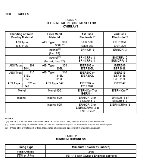
- (*)Materials for weld overlay shall be specified by the Owner’s Engineer and shall comply with Table 1. Any request for a change in the specified material in this table or for a material substitution not listed in this table shall include the proposed material’s ASME Code Designation, material grade, service properties and any previous known history in the proposed service environment.
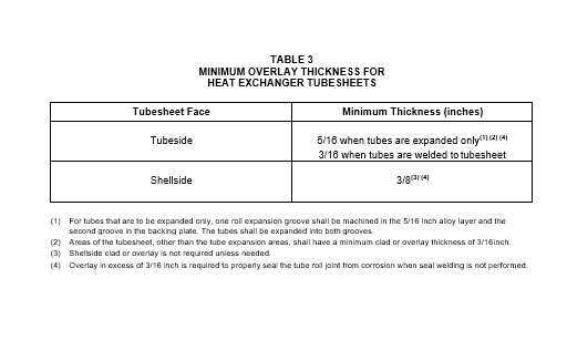
- (*)The minimum overlay thickness shall be as shown in Table 2 for all components except heat exchanger tubesheets. The minimum overlay thickness for heat exchanger tubesheets shall be as shown in Table 3
- Austenitic stainless steel materials that will be subjected to PWHT after the repair shall be “L” grade, or stabilized with additions of Ti or Cb.
WELD OVERLAY REQUIREMENTS
- Weld Overlay procedures shall be qualified in accordance with Section IX of the ASME Code, but shall use the same P–Number base material and type or brand of flux, weld wire, or electrode as that to be used in production welding. The postweld heat treatment temperature range used on the overlay qualification test plates shall be the same as that used in production. The postweld heat treatment time at temperature for the qualification test plates shall be the same or greater than that used in production.
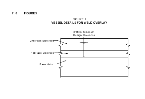
- (*)All weld overlay procedures and production welds shall have a minimum of two weld layers unless approved by the Owner’s Engineer. The number of weld layers used in production welds shall not be less than the number used for procedure qualification. See Figure 1 for a general sketch of a weld overlay.
- The weld overlay shall be applied in such a manner that the weld beads run circumferentially around the vessel. The surface contour shall be relatively smooth. Waviness is permissible but without notches and undercuts which might act as stress raisers. The beads may run longitudinally for nozzles with an inside diameter of 12 inches and smaller and for pipe elbows if followed by blend grinding. Beads should overlap by a minimum of 1/3 of the bead width.
- Alloy Limitations for Austenitic Stainless Steel are listed below:
- For any low–carbon (L, LC, or ELC) grades, the percent carbon shall not exceed 0.04 percent.
- For columbium (niobium) bearing grades (e.g., 347 and 309 Cb) the columbium to carbon ratio of the deposited metal shall not exceed 16:1.
- For weld overlay either FCAW or SMAW automated methods are preferred. If the surface preparation is marginal, FCAW is preferred. The overlay contractor shall perform a quality check on the overlay equipment at a minimum at the beginning of each shift to ensure proper chemistry and overlap of beads. Manual overlay is required at areas the automated equipment cannot reach or for nozzles and attachments.
- Vessels with Monel weld overlay designated for HF Acid service shall have the following requirements:
- Vessel overlay chemistry shall contain a maximum of 5% iron (Fe) in the top 1/16 inch of the final deposit.
- Overlays, deposited by manual processes, shall have a minimum of three layers.
- ERNi-1 filler metal is required for the first pass when welding with the GTAW or GMAW process.
- The maximum diameter of SMAW electrodes shall be 1/8 inch.
- Inspection requirements for weld overlay shall be per 9.0.
NOZZLES AND MANWAYS
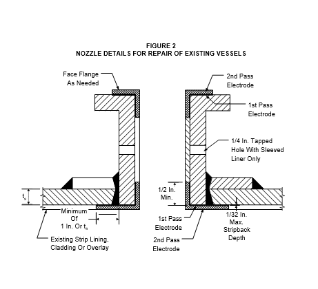
- Nozzles NPS 3 inches and larger shall be weld overlaid, see Figure 2. For nozzles smaller than NPS 3 inches, sleeve liners or overlay may be used. The overlay or sleeve shall be the same material and thickness as used for the overlay of the vessel or head to which they are attached.
- Flange faces of lined nozzles and manways that are weld overlaid with corrosion–resistant alloy shall be finish–machined over the gasket area, see Figure 2. Machined overlay shall be 3/16 inch minimum thickness and comply with requirements for weld overlays outlined in this Practice.
- Replacement of an existing liner or sleeve with a new one is an acceptable method of repair. Repair of existing liners and sleeves shall satisfy the following requirements.
- (*)Sleeves or strip lining may be installed as a repair, but shall not be used, unless otherwise approved by the Owner’s Engineer, if the vessel is subject to PWHT after installation, design temperature exceeds 700 F, or design pressure exceeds 250 psi.
- Alloy sleeve liners shall be either seamless or rolled and welded with full fusion GTAW weld, before being inserted into a nozzle neck. The liner shall be rigidly attached to the vessel shell.
- Sleeve liners shall be welded to the connection at their extremities with welds of sufficient cross–section to develop the full strength of the sleeve liner and to withstand forces due to differential expansion. Weld overlay shall be used for the flange facing, see Figure 2.
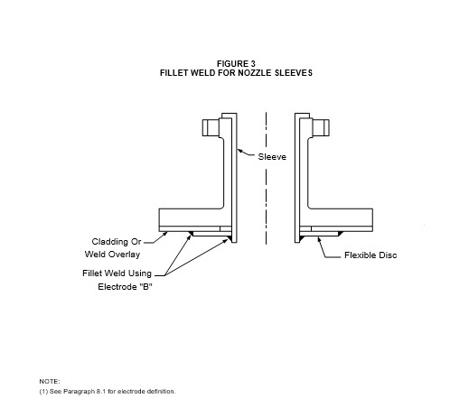
- (*)Sleeve designs using a flexible disc - similar to that illustrated in Figure 3 shall be submitted for review and approval by the Owner’s Engineer.
ATTACHMENT OF INTERNALS
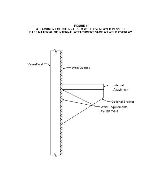
- When the base material of the attachment is the same as the overlay material, the attachment shall be welded directly to the weld overlay, see Figure 4.
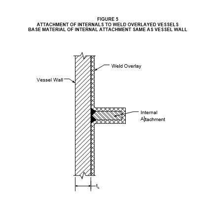
- When the base material of the attachment is the same as the base material of the vessel shell, the attachment shall be welded directly to the shell using a full penetration weld. The attachment and the shell in the vicinity of the attachment shall then be weld overlaid with a material that is compatible with the overlay lining of the vessel, see Figure 5.
INSPECTION AND TESTING
- Weld Overlay
- Weld overlay deposit shall be a minimum of 3/16” thick.
- (*)Weld Overlay Deposits shall be inspected to the following requirements unless otherwise specified by the Owner’s Engineer.
- The ultrasonic examination technique shall be per ASME Code Section II, SA 578, Supplement S-6. All ultrasonic testing shall use a transducer of approximately 1 inch diameter except for nozzles, which may use smaller diameters to accommodate the nozzle circumference.
- For weld overlayed heads, each head shall be inspected by ultrasonic testing of two 6 inch wide strips tested at 90 degrees such that they intersect at the center of the head.
- For weld overlayed nozzles, inspection shall be from either the inside diameter or outside diameter. The inspection path shall be a 3 inch wide strip around the nozzle circumference.
- All areas for structural attachments shall be inspected for overlay disbonding before welding of the attachment in place.
- For all inspections, indications of disbond greater than 1 inch diameter in any direction shall be cause for rejection.
- PMI examination of weld consumables prior to welding shall be in accordance with EP 15–1–4. Chemical analysis of weld overlay deposits shall be taken at a minimum depth of 1/16 inch below the final surface of the weld. Results of the chemical analysis shall meet the deposit analysis of undiluted weld metal. Chemical analysis shall be taken at approximately 8 foot intervals along the shell and from each head.
- Liquid penetrant examination shall be done on 10% of the first layer of weld deposit. Inspection shall include as many “T” joints as possible.
- Completed weld overlay and attachment welds to overlay, shall be 100 percent liquid penetrant examined. Examination and acceptance criteria shall be per EP 7–1–1.
- The ferrite number for austenitic stainless steel weld overlay procedures and production welds shall be between 3 and 12FN as determined by the WRC 1988 diagram for ferrite prediction in stainless steels. Ferrite content for production welds shall be checked by a Ferritescope or chemical analysis. The Ferritescope shall be calibrated using the AWS Standard A4.2. If the production weld is subject to Post Weld Heat Treatment, the ferrite reading shall be measured before PWHT. The extent of the testing shall be one test per:
- Every 10 square feet of continuous overlay
- Each nozzle or manway installation
- Each new spool of continuous overlay strip or wire electrode
- Strip Lined Nozzles
- Any vessels requiring hydrostatic testing and any joint requiring radiographic examination shall be so tested before the lining is applied.
- The final pass of all strip lining attachment butt welds and all exposed fillet welds shall be examined by the Liquid Penetrant Method. Examination and acceptance criteria shall be per EP 7–1–1. Alternate methods of examination may be used with approval of the Owner’s Engineer.
© 2026 Inflection Point Engineering, LLC. All rights reserved. The content of this page — including calculation methods, reference data, written analysis, interactive tools, and source code — is the intellectual property of Inflection Point Engineering, LLC and is protected under applicable copyright, trademark, and trade secret laws. Unauthorized reproduction, redistribution, modification, or derivative use in whole or in part is prohibited without prior written consent.
Disclaimer. This material is provided for informational and educational purposes only and does not constitute professional engineering advice. Calculations, reference data, and methodologies are based on published standards and accepted engineering practice but are not a substitute for engineering judgment, site-specific analysis, or review by a licensed Professional Engineer. Inflection Point Engineering, LLC makes no warranties, express or implied, regarding the accuracy, completeness, or fitness for a particular purpose of any content presented here, and shall not be liable for any direct, indirect, incidental, or consequential damages arising from its use. Users assume all risk associated with applying this content to real-world design, operations, or decisions.
© 2026 Inflection Point Engineering, LLC. All rights reserved.