 Section 7 — Pressure Vessels
Cyclone Systems for Fluid Catalytic Cracking Units
IPE Engineering Practice IPE-EP-7-2-3
Document number: IPE-EP-7-2-3 · Section: 7 — Pressure Vessels

SCOPE
- This Practice covers mandatory requirements governing the design, fabrication, inspection, and testing of new reactor and regenerator cyclones and cyclone systems for fluid catalytic cracking units.
- External cyclones constructed to the ASME Code shall be in accordance with EP 7-1-1, and the applicable requirements of this Practice.
- The Manufacturers may quote alternates to this Practice; however, all variances must be clearly indicated in the proposal and require approval of the Owner's Engineer.
- Any deviation to this Practice shall be approved by the procedure in EP 1-1-3.
- An asterisk (*) indicates that a decision by the Owner or Owner's Engineer is required or that additional information is furnished by the Purchaser.
- A Revision Bar indicates all changes made to this Revision.
2.0 REFERENCES
The latest edition of the following standards and publications are referred to herein.
STANDARDS AND PUBLICATIONS
| Engineering Practices |
|---|
| EP 1-1-3 Deviations to Engineering Practices EP 7-1-1 Pressure Vessels EP 7-1-5 Welding Requirements for Pressure Vessels EP 7-2-3 DS FCCU Cyclones Data Sheet EP 11-1-1 Internal Insulating and Refractory Lining EP 15-1-4 Positive Materials Identification (PMI) |
| ASME Codes |
| Sec VIII Pressure Vessels, Division I |
DEFINITIONS
- Contractor - Company or business that agrees to furnish materials or perform specified services at a specified price and/or rate to the Owner.
- Inspector - A Refining Company appointed engineer or inspector.
- Manufacturer - The recipient of a direct or indirect purchase order for materials and/or equipment. In this context, a direct order is one issued to a manufacturer by a contractor or the Owner. An indirect order is one issued to a manufacturer by a vendor (recipient of a direct order) for materials, fabricated components, or subassemblies.
- Owner - Refining Company.
- Owner's Engineer - A Refining Company appointed engineer.
- Purchaser - The party placing a direct purchase order. The purchaser is the Owner's designated representative.
GENERAL REQUIREMENTS
- (*)The Manufacturer shall be responsible for the process and mechanical design of cyclones, or cyclone systems, based on the information contained in this Practice. The design shall also conform to the requirements of other Engineering Practices where applicable, and to any other supplementary specifications supplied by the Purchaser for specific projects or installations.
- (*)The Cyclone System Process Design and Mechanical Design Data Sheets, as given in EP 7-2-3 DS will be prepared by the Owner's Engineer for each cyclone system and will contain all the information required for design.
- (*)The Owner's Engineer will provide arrangement and detail drawings for the reactor and regenerator vessels, and for all vessel internals. The Owner's Engineer will also specify the normal, maximum and minimum catalyst bed levels in the vessels.
- (*)The Process Design Data Sheets shall include, as a minimum, all process data for normal, maximum and turndown operating conditions, and full details of the equilibrium catalyst in the FCCU. The Data Sheets are provided in EP 7-2-3 DS.
- (*)For direct coupled cyclone systems in reactor vessels, separate data sheets shall be prepared for the primary (riser) cyclones and the secondary cyclones.
- (*)For units with proprietary catalyst separation devices installed upstream of cyclones, the Owner's Engineer shall specify the cyclone inlet dust loadings.
- (*)The Manufacturer shall take account of the following during design.
- Catalyst addition and withdrawal rates.
- The replacement of cyclones in one vessel only will affect the particle size distribution of the equilibrium catalyst. This may, in turn, affect the performance of existing cyclones in the unit. This aspect must be considered when calculating efficiencies and catalyst losses. A current Cyclone Operation Data Sheet shall be provided by the Owner's Engineer for both vessels if there will be a significant change in the efficiency of one vessel's cyclones and the existing cyclones are retained in the other vessel. This Data Sheet may be provided for other cases, at the option of the Owner's Engineer. The Data Sheet is provided in EP 7-2-3 DS.
DOCUMENTATION
- Proposal Requirements
- For each cyclone system, the Manufacturer shall supply with his proposal all the relevant information necessary for appraisal of the process performance of the system which shall include but not be limited to the following:
- A completed cyclone data sheet, see EP 7-2-3 DS.
- Number and type of cyclones and number of stages.
- Mechanical design temperatures and mechanical collapsing pressure.
- Cyclone system loads
- Total dead load
- Operating catalyst load
- Flooded catalyst load
- Total operating load
- Total flooded load
- Materials of construction including refractories.
- Description of any areas that are proposed to be stellite faced rather than refractory lined.
- The following shall be stated for each of the specified operating cases:
- Pressure and temperature at the inlet of the primary cyclone.
- Apparent gas density.
- Inlet and outlet velocities at each stage.
- Design dust loading at the inlet and outlet of the cyclone system.
- Catalyst particle size distribution at the cyclone system inlet and outlet.
- Dipleg catalyst levels and catalyst densities.
- Dipleg catalyst loadings.
- Pressure drop across each cyclone.
- Estimated catalyst loss and guaranteed catalyst loss.
- A fully dimensioned drawing showing the sizes and arrangement of the cyclones, as per the data sheet EP 7-2-3 DS, Sheet 6 of 6 shall be included in the proposal. All design dimensions and data on this sheet must be included. Also, a list of any proposed sub-contractors for fabrication and material suppliers shall also be included.
- Documents Required for Approval Prior to Fabrication
- (*)After the award of an order for a cyclone system and within the agreed time period between the Owner's Engineer and the Manufacturer, the Manufacturer shall submit to the Owner's Engineer the following for approval:
- Detailed fabrication drawings showing nozzles, reinforcement, hanger, lugs, bracing, hexmesh attachment and plenum details.
- Full welding procedures for all seam welds, nozzle welds and welds for reinforcement and major attachments, and for hard-facing overlay. The procedures shall be clearly identified on general arrangement and detail drawings, or other appropriate documents.
- A full set of calculations to demonstrate compliance with the design requirements of this Practice.
- Material procurement and fabrication schedule.
- An outline installation procedure followed by a fully detailed procedure at least one month before delivery of the cyclone system.
- Details of the Manufacturer's inspection schedules including radiography and NDT.
- Refractory testing, inspection, installation, and heat curing plans.
- Thermal calculations, including thermal stress analysis.
- Fabrication Tolerances.
- "In-Field" cyclone air test procedure.
- Final Reports
- (*)On completion of fabrication, a dossier shall be assembled and delivered with each cyclone system. It shall contain the following:
- All "as built" drawings, reduced to a maximum of A3 size.
- Material test certificates.
- Radiography and other non-destructive testing records.
- Ferrite check location sketches.
- Welding procedures, cross referenced to the location drawings.
- Welding procedures and welder's performance qualifications.
- All mechanical design calculations.
- Refractory lining test sample data and dryout records.
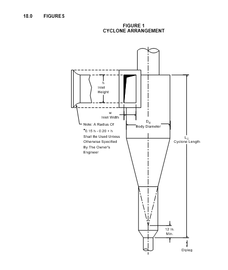
CYCLONE ARRANGEMENT
- (*)Cyclone systems shall be arranged such that the diplegs and bracing do not interfere with any vessel internals; in particular with risers and riser distributor arms (tee-arms) in reactors and UOP high efficiency regenerators. The dipleg angle shall not exceed 15 degrees from the vertical unless approved by the Owner's Engineer. Where possible the dust hopper outlets should be located above the level of the tee-arms.
- Two-stage systems shall be provided for regenerators.
- (*)Unless otherwise specified by the Owner's Engineer, single stage, high efficiency cyclones should be provided for reactors.
CYCLONE DESIGN CRITERIA
- Grassroot Designs
- (*)The cyclone design shall be based initially on the following design criteria. If the Manufacturer cannot meet these criteria, any exceptions must be approved by the Owner's Engineer before the Manufacturer submits drawings for approval.
- (*)Unless approved by the Owner's Engineer, the maximum vapor inlet and outlet velocities shall be as shown in Table 1.
- (*)The vapor outlet pipe penetration into the cyclone shall be 80% of the cyclone inlet duct height unless approved by the Owner's Engineer.
- (*)The cyclone dimensions shall be in accordance with the parameters from Table 2 which are shown in Figure 1. These parameters are not intended for use in rough cut cyclones such as those in closed-coupled cyclones. Dimensions for these cyclones are subject to the approval of the Owner's Engineer.
- The projected apex of the main cone shall be 12 inches or 0.3* DB, whichever is greater, above the dustbowl outlet as shown in Figure 1.
- The main cone outlet shall be sized to give a catalyst mass flux of approximately 80 lb/sec/ft2.
- Diplegs for single stage and first stage cyclones shall be sized to give a catalyst mass flowrate between 100 and 150 lbs/sec/ft2.
- The minimum dipleg diameter permitted is 8 inches.
- (*)Unless approved by the Owner's Engineer, the catalyst level in the dipleg shall be no higher than 7 feet below the top of the dipleg.
- 7.2 Replacement Cyclones
The criteria specified in Section 7.1 are for grassroots installations and, where possible, for replacement cyclones. However, it may not be possible or desirable to retain all these criteria for expansion replacement cyclones. For example, reversed series cyclones are not permitted by paragraph 7.1.4 but are often useful for de-bottlenecking. Therefore, the Manufacturer is encouraged to present abase case design meeting the criteria of Section 7.0 and alternative designs meeting the manufacturer's criteria and backed by commercial experience.
MECHANICAL REQUIREMENTS
- Design
- (*)The mechanical design for the cyclone system shall be suitable for the temperatures and pressures specified on the Mechanical Design Data Sheet by the Owner's Engineer.
- The mechanical design for cyclone systems, plenums and all supports shall be in accordance with the criteria stipulated in.
- Cyclone Supports for Two Stage Systems
- First stage cyclones shall be supported by hanging from cyclone support rods or straps. The support rods or straps shall be connected to the cyclone barrel. All cyclone rods, straps or supports must be oriented to allow for differential thermal expansion between the cyclones, plenum chamber and the vessel wall. Second stage cyclones may also be supported as described for the first stage or alternatively supported by welding the outlet tubes to nozzles in plenum chambers or to individual nozzles located in the vessel top head.
- Second stage cyclones which are supported by their gas outlet tubes shall have minimum 1/2 inch thick flanges for temporary support and alignment. The flanges shall have four equally spaced slotted holes, 1-1/8 inch x 3 inch for alignment prior to welding. The inside of the outlet tubes shall be beveled for welding. After installation, the flanged joint shall be bridged by a full penetration weld of the gas outlet tube.
- (*)The cyclone supports shall be designed to minimize the differential thermal growth between cyclone supports; including hanger rods, plenum, vessel wall and gas outlet tube. The support system shall be designed to minimize differential elongation due to creep. The cyclone supports must fully accommodate any differential movements that occur during start-up, normal operating and shutdown cycles as specified on the Mechanical Design Data Sheet. The cyclone supports must accommodate continuous cycling between the normal operating and intermittent operating temperature.
- Cyclone Supports for Single Stage Systems
The cyclones may be supported in the same manner as that specified above for second stage cyclones.
- Reinforcement
- The Manufacturer shall provide adequate reinforcement for the cyclones suitable for the design pressures specified. In addition, reinforcement shall be provided to accommodate the method of cyclone support.
- (*)The reinforcement shall consist of stiffening components such as plate, flat bar, tee or angle. Plate thickness, or combinations thereof to meet reinforcement requirements, shall be equal to or greater than the minimum specified plate thickness for the cyclone. The Manufacturer shall clearly indicate the proposed reinforcement on the initial proposal drawings. The final reinforcement design shall be supported by calculations submitted for review and approval by the Owner's Engineer.
- Radially oriented reinforcing ribs on top of the cyclone shall have a minimum 1 inch radius notch at the gas outlet tube to cyclone joint.
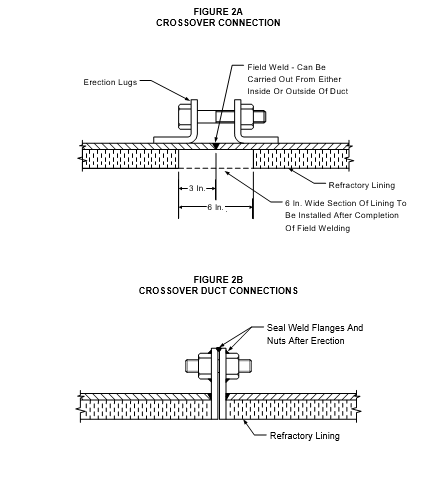
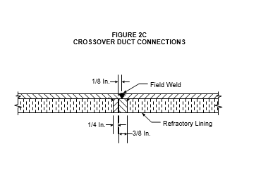
- Cross-Over Duct
- The connection in the cross-over duct between first and second stage cyclones shall be as shown in either Figure 2A, Figure 2B, or Figure 2C.
- (*)Figure 2A applies when there is sufficient access for internal welding and lining, and Figure 2B or Figure 2C when only external welding is possible. For either connection, four 1-inch diameter bolts should be provided for alignment and duct support during welding. Alternate positioning techniques may be prepared and are subject to the approval of the Owner's Engineer.
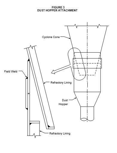
- Dust Hopper
- (*)To facilitate maintenance during shutdowns on cyclones with dust hoppers with an inside diameter of 36 inches and less (including refractory lining), the Manufacturer shall provide field weld attachments as shown in Figure 3. The fillet welds shall be designed for the weight of the diplegs and dust hopper full of catalyst, including the weight of trickle valves and bracing. All fillet weld loadings shall be fully checked and the calculations submitted for approval by the Owner's Engineer.
- The dust hopper outlets shall be designed to provide an inside diameter which, after installation of a refractory lining with a thickness equal to that in the cyclone body, is equal to the dipleg inside diameter. The lining shall extend for a length of 36 inches below the dust hopper. This enlarged extension shall terminate with a 9 inch long stub equal in wall thickness and inside diameter to the dipleg. The stub end shall be beveled for field welding to the dipleg.
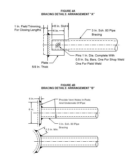
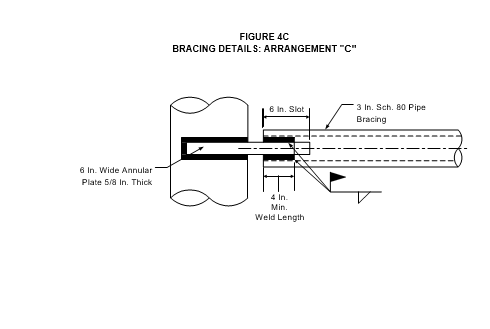
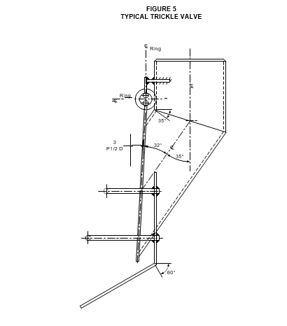
- Bracing
- (*)The Manufacturer shall provide truss-type cross bracing on a horizontal plane between cyclones and on a minimum of two levels between diplegs. If two levels of cross bracing are provided, the manufacturer shall quote the price for an optional third level. Bracing of cyclones or diplegs to the vessel wall or refractory is subject to the approval of the Owner's Engineer.
- The lowest natural frequency of the cyclone system, considering normal catalyst loading, shall be greater than 4 Hertz (cycles/sec).
- The bracing shall be fabricated with a minimum of NPS 3 inch Schedule 80 seamless or welded pipe of the same material as that specified for the cyclones.
- (*)The end attachments for bracing pipes shall be in accordance with Figure 4A, Figure 4B, or Figure 4C, unless otherwise specified by the Owner's Engineer. The bracing attachment clips shown in Figure 4A shall be supplied for field fitting. The pad plates shown in Figure 4B and the annular plates shown in Figure 4C shall be shop fitted.
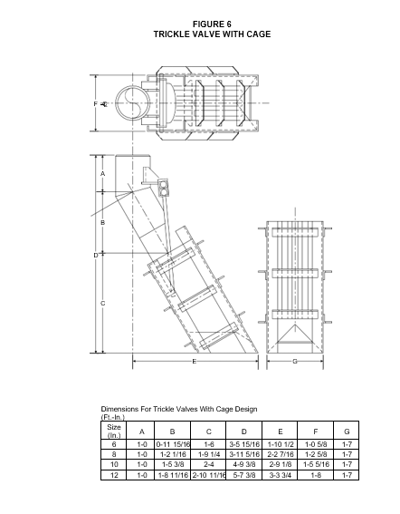
- Dipleg Valves
- (*)Angled trickle valves shall be provided for diplegs where required. Trickle valves shall be in accordance with Figure 5 for services with catalyst velocities or 3.5 ft/sec and less. For catalyst velocities greater than 3.5 ft/sec, trickle valves shall be in accordance with Figure 6, unless otherwise approved by the Owner's Engineer. Other designs may be submitted for acceptance and approval by the Owner's Engineer.
- When dipleg valves are not specified, for example, for certain first stage diplegs terminating in a catalyst bed, shallow cone baffles shall be provided.
- (*)The trickle valves shall have shrouds to suit operation in vapor space or in fluidized beds as specified by the Owner's Engineer.
- The dipleg valve and baffle materials shall be the same as the cyclone material to which they are attached.
- (*)The plates on trickle valves shall have a 1-9/16 inch minimum wide band of hard facing over the seating area. The hard facing material shall be in accordance with paragraph 10.6 . Other designs using refractory may be proposed as alternatives subject to approval of the Owner's Engineer.
- Access for Inspection and Repairs
The following provisions for access into the cyclones for inspection and repair shall be provided.
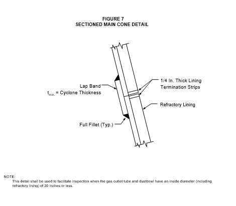
- A sectioned main cone shall be provided when the gas outlet tube and the dustbowl (see Figure 1) have an inside diameter (including refractory lining) of 20 inches or less. The sections shall be joined by a lap band fillet welded to each section, see Figure 7. The refractory lining for each section shall be terminated with 1/4 inch thick lining termination strips.
- For primary cyclones in two stage cyclone systems, when the inlet horn is less than 9 inches by 18 inches inside dimensions after refractory lining, provide a manway directly above the gas outlet tube. The manway shall be completely seal welded. The manway shall be lined; the lining shall be flush with the duct lining.
- Installation
- Installation of a cyclone system may be carried out by one of the following methods:
- Through the vessel manway.
- Through an opening cut in the vessel wall.
- By removal of the vessel top head.
- (*)The method to be used in each particular case shall be specified by the Owner's Engineer. Regardless of the installation method, the cyclones shall be sized to fit through the main vessel access manway unless otherwise approved by the Owner's Engineer.
- For whichever method selected, the Manufacturer shall give careful consideration to the design to ensure that future repairs, replacement of parts or complete cyclone replacement, can be carried out with minimum FCCU downtime.
MATERIALS
- (*)Unless otherwise specified by the Owner's Engineer the initial proposals for regenerator cyclone systems shall be based on the materials listed in Table 3.
- (*)Unless otherwise specified by the Owner's Engineer, the initial proposals for reactor cyclone systems with a design temperature less than 1000F, shall be based on the materials listed in Table 4.
- (*)Unless otherwise specified by the Owner's Engineer, the initial proposal for reactor cyclone systems with design temperatures greater than 1000F and less than or equal to 1100F shall be based on the materials listed in Table 5.
- The minimum thickness of the cyclone components shall be as shown in Table 6.
EROSION RESISTANT LINING
- All cyclones shall be lined with a 1.0 inch lining system. The refractory and anchor system shall be in accordance with EP 11-1-1.
- The Manufacturer shall ensure that suitable access is available for satisfactory installation of the refractory lining.
- The hexmesh (or alternative anchor materials) shall be ASTM A-240 Type 304H for stainless steel cyclones, and ASTM A240 Type 410 S for carbon steel or Low chrome cyclones (P- Numbers 3, 4, and 5).
- The lining shall be installed in the following locations:
- Entire internal surface of cyclone including the outside diameter of the outlet tube where it extends into the cyclone body.
- Entire internal surface of dust hoppers including the 36 inch extensions to the dust hopper stubs.
- Entire internal surface of gas outlet tubes and crossovers.
- (*)The diplegs and dipleg bracing shall also be partially lined externally where necessary for protection against impact of catalyst from risers, etc. The location of this refractory lining will be specified by the Owner's Engineer.
- (*)All refractory linings shall be fully cured before shipment of the cyclones. The Manufacturer shall provide dryout schedules in accordance with EP 11-1-1.
- Any areas exposed to severe erosion where erosion resistant refractory lining is impractical shall be hard faced with a 3/16 inch thick weld overlay of Stellite or equivalent material. Stellite No. 6 shall be used for design temperatures below 1200F. For design temperatures of 1200F and above, the hard facing shall be Stellite No. 1. The Manufacturer shall note all hard facing locations in the proposal.
QUALITY ASSURANCE
- (*)The Manufacturer will be expected to operate a quality control system to ensure that the technical requirements of this Practice are achieved. The Manufacturer's quality control system shall be based on the appropriate part of ASME Section VIII. The Owner's Engineer may require demonstration of the quality control system but this may be waived if the system has been verified recently by an accreditation scheme acceptable to the Owner's Engineer. The Manufacturer's quality assurance manual must be available upon request of the Owner's Engineer.
- (*)The Manufacturer may be required to submit a quality control plan which would be subject to approval by the Owner's Engineer. The implementation of such a quality control plan may be subject to monitoring by the Owner's Engineer and in addition, may be audited following an agreed period of notice. Any requirement for a quality control plan will be specified by the Owner's Engineer in the inquiry and purchase documentation.
- The Manufacturer shall ensure that technical and Quality Assurance (QA) requirements specified in the inquiry and purchase documents are applied to all materials, equipment and services provided by sub-contractors and to free issue materials.
FABRICATION
- General
- (*)The Manufacturer shall have full responsibility for mechanical design, fabrication, quality of materials, and quality of workmanship for both cyclones and refractory lining. This applies even when the Owner's Engineer may have specified a particular refractory lining installer. Approval of the Manufacturer's drawings by the Owner's Engineer shall not relieve the Manufacturer of any of these responsibilities.
- (*)The Manufacturer may place orders for materials, after award of the order, if the materials are in accordance with this Practice, or if alternative materials have been specified or approved by the Owner's Engineer.
- (*)The Manufacturer shall proceed with fabrication only when the manufacturer's drawings, calculations, procedures and material certificates have been approved by the Owner's Engineer.
- (*)The Manufacturer shall re-submit any revisions of drawings or procedures for further approval by the Owner's Engineer.
- Welding
- (*)All welding shall be done with welding procedures that are in accordance with EP 7-1-5. All welding procedures are subject to the approval of the Owner's Engineer. All permanent welds shall be made by certified welders who have passed the procedure qualification tests.
- All butt welds shall be full penetration and full fusion. All lap joints on the dust pot, and on the main cone when required by Section 8.2 for access, shall be a full fillet weld. All fillet welds shall have complete fusion at the root.
- (*)The interior surface of cyclone welds that are unlined (i.e., dipleg) and exposed to erosive conditions shall be smooth with no internal projection, by using a TIG root pass, grinding, or other method acceptable to the Owner's Engineer.
- (*)Fillet welds identified as Category A or B in the stress analysis shall have the weld toes blended smooth with an inert gas wash pass. Grinding with the wheel perpendicular to the weld line may be used instead if accepted by the Owner's Engineer.
- The ferrite content of production welds shall be 6% plus or minus 3% for AISI Type 304 or other austenitic stainless steel cyclones.
- AISI Type 304H material shall be welded with E308 electrodes with a minimum carbon content of 0.04%.
- Cyclone Tolerances and Fit-up
- (*)All fabrication tolerances shall be per the Manufacturer's standard, and shall be submitted for approval to the Owner's Engineer.
- On completion of fabrication of cyclones for two stage systems, the cyclones shall be "paired" at the Manufacturer's works and match-marked during the trial assembly of cross-over duct, etc. The match-marking shall be clearly shown on the relevant arrangement and detail drawings to ensure correct on-site assembly.
- Cyclones, dust hoppers and diplegs shall be match-marked as necessary during fabrication to ensure correct re-assembly after refractory lining.
INSPECTION
- General
- (*)The materials, fabrication and trial assembly of cyclone systems shall be subject to inspection for approval by the Owner.
- The Inspector shall be permitted entry to the Manufacturer's shop where and while the work is being performed. The Manufacturer shall afford the Inspector reasonable facilities to satisfy themselves that the cyclone system is being furnished in accordance with the requirements specified.
- The Manufacturer shall give the Purchaser at least 5 days prior notification of the following:
- The start of fabrication.
- The dates of final weld examinations for individual cyclones.
- The dates of completion of hexmesh installations in individual cyclones.
- The commencement of refractory installation.
- The date for trial assembly of two stage cyclone systems.
- Production welds on 18-8 stainless steel cyclones shall be spot checked for ferrite content using a suitable ferrite meter. The instrument used for the test shall be calibrated against a known standard test piece.
- Positive Materials Identification for alloy materials shall be in accordance with EP 15-1-4.
- Radiographic Examination
- (*)The following welds shall be 100% radiographically examined in accordance with the ASME Code, Section VIII, Division 1, Paragraph UW-51. Where radiographic examination is not possible, the root and final pass of the weld shall be magnetic particle examined, or liquid penetrant examined for non-magnetic materials.
- Any bimetallic weld.
- Cyclone outlet to plenum or vessel head welds.
- Any weld specified by the Inspector.
- Ten percent of butt welds, other than those requiring 100% examination, at locations approved by the Inspector, shall be subject to spot radiographic examination in accordance with the ASME Code Section VIII, Division 1, Paragraph UW-52.
- Magnetic Particle and Liquid Penetrant Examination
- Magnetic particle examination and acceptance criteria shall be in accordance with the ASME Code Section VIII, Division 1, Appendix 6.
- Liquid penetrant examination and acceptance criteria shall be in accordance with the ASME Code Section VIII, Division 1, Appendix 8.
- All fillet welds shall be 100% magnetic particle examined, or liquid penetrant examined for nonmagnetic materials.
TESTING
- (*)Unless otherwise specified by the Owner's Engineer, cyclone systems shall be leak tested by the Owner after installation. The Manufacturer shall provide a suitable test procedure for the particular cyclone installation, for approval by the Owner's Engineer. The test medium shall be plant air and the test shall be carried out at a minimum pressure of 1 psi above the design pressure drop for the cyclone system, but no less than 3 psig. A soap solution shall be used to test all welded joints during the air test.
- If a leak test is not performed per paragraph 14.1, all field butt welds shall be inspected using either the magnetic particle or liquid penetrant method.
PACKAGING AND SHIPPING
- Before shipping, the following measures shall be applied:
- External surfaces of cyclones, diplegs, etc., shall be cleaned of weld scabs and splatter.
- All cyclone openings shall be blanked off with hardboard and heavyduty plastic sheeting, and sealed with tape to make the protection waterproof.
- Refractory linings on diplegs and dipleg valves shall be covered with heavyduty plastic sheeting and sealed with tape to make waterproof.
- All stainless steel components shall be protected from salt water to prevent chloride stress corrosion cracking during all phases of fabrication and shipping.
GUARANTEE
- The Manufacturer shall guarantee that the catalyst collection efficiency of the equipment supplied will satisfy the operating conditions specified.
- The Manufacturer shall guarantee that the equipment supplied is free from defects in design, workmanship and material, and that the material is of the specified grade.
17.0 TABLES
TABLE 1
MAXIMUM VAPOR VELOCITIES
| CYCLONE TYPE | INLET (ft/sec) |
OUTLET (ft/sec) |
|---|---|---|
| Single Stage First Stage Regenerator Second Stage Reactor Second Stage |
65 65 80 80 |
100 80 130 100 |
TABLE 2
CYCLONE DIMENSIONAL MINIMUM RATIOS
| CYCLONE PARAMETER | CYCLONE TYPE | CYCLONE TYPE | CYCLONE TYPE |
|---|---|---|---|
| Single Stage | First Stage | Second Stage | |
| LC /DB h/w AB /Ai |
5.5 2.25-2.4 5.5 |
5 2.25-2.4 3.7 |
5 2.25-2.4 4.3 |
NOTES:
- LC is the cyclone length (See Figure 1).
- DB is the inside barrel diameter (See Figure 1).
- h is the inlet duct height (see Figure 1).Figure 1
- w is the inlet duct width (See Figure 1).Figure 1
- AB is the barrel area (DB2/4).
- Ai is the inlet duct area (h x w).
- All values are minimum unless a range is given.
TABLE 3
REGENERATOR CYCLONE MATERIALS
| ITEM | MATERIAL |
|---|---|
| Plate and Pipe Material Pipe Stud Bolts Hex Nuts Hanger Rods and Pins |
ASTM A-240, Type 304H ASTM A-312, Type 304 ASTM A-193, Grade B8 Class 1(1) ASTM A-194, Grade 8M ASTM A-479, Type 304H |
NOTE:
(1) One (1) inch minimum diameter.
TABLE 4
REACTOR CYCLONE MATERIALS, FOR DESIGN TEMPERATURE LESS THAN OR EQUAL TO 1000F
| ITEM | MATERIAL |
|---|---|
| Plate Pipe Stud Bolts Hex Nuts Hanger Rods and Pins |
ASTM A515 ASTM A193, Grade B16 ASTM A106 ASTM A194, Grade 2H ASTM A675, Grade 65 or 70 |
TABLE 5
REACTOR CYCLONE MATERIALS, FOR DESIGN TEMPERATURES GREATER THAN 1000F AND LESS THAN 1100F
| ITEM | MATERIAL |
|---|---|
| Plate Pipe Stud Bolts Hex Nuts Hanger Rods and Pins |
ASTM A387, Gr11, Class 1 ASTM A335, Grade P11 ASTM A193, Grade B16 ASTM A194, Grade 2H ASTM A739, Grade B11 |
NOTE:
(1) A different material selection may be required for high sulfur feedstocks.
TABLE 6
MINIMUM THICKNESS OF CYCLONE COMPONENTS
| COMPONENT | REGENERATOR | REACTOR |
|---|---|---|
| Body and Cone Dust Hopper Outlet Tubes Reinforcing Gussets and Miscellaneous Plate |
3/8 inch minimum | 3/8 inch minimum |
| Dipleg-Pipe Dipleg Baffles | Sch XS 1/2 inch minimum |
Sch XS 1/2 inch minimum |
| Trickle Valves | In accordance with Manufacturer's standard but not less than 1/2 inch | In accordance with Manufacturer's standard but not less than 1/2 inch |
© 2026 Inflection Point Engineering, LLC. All rights reserved. The content of this page — including calculation methods, reference data, written analysis, interactive tools, and source code — is the intellectual property of Inflection Point Engineering, LLC and is protected under applicable copyright, trademark, and trade secret laws. Unauthorized reproduction, redistribution, modification, or derivative use in whole or in part is prohibited without prior written consent.
Disclaimer. This material is provided for informational and educational purposes only and does not constitute professional engineering advice. Calculations, reference data, and methodologies are based on published standards and accepted engineering practice but are not a substitute for engineering judgment, site-specific analysis, or review by a licensed Professional Engineer. Inflection Point Engineering, LLC makes no warranties, express or implied, regarding the accuracy, completeness, or fitness for a particular purpose of any content presented here, and shall not be liable for any direct, indirect, incidental, or consequential damages arising from its use. Users assume all risk associated with applying this content to real-world design, operations, or decisions.
© 2026 Inflection Point Engineering, LLC. All rights reserved.