 Section 7 — Pressure Vessels
Fractioning Tray and Tower Packing
IPE Engineering Practice IPE-EP-7-2-2
Document number: IPE-EP-7-2-2 · Section: 7 — Pressure Vessels
Figure 2 Area And Dimensional Data For Bubble Caps……………………………………18
Figure 3 Recommended Chimney Tray Cap Design for Vacuum Service……………….19
SCOPE
- This Practice covers supplemental requirements for the rating, design, materials, construction, installation, inspection and testing of trays, packing and other column internals. General requirements for these components are covered in EP 7-2-1.
- This Practice applies to all types of trays including valve trays, sieve trays, bubble cap trays, dual flow trays, etc. as well as random, structured and other proprietary packings. It further applies to other column internals and attachments such as tray rings, distributors, seal pans, drawoff pans.
- This Practice is supplementary to process load sheets, process or mechanical sketches, tray or column internal drawings and other Practices related to a specific job.
- This Practice applies specifically to columns 30 inches in diameter or larger. Small columns may require exceptions to this Practice.
- Any deviation from this Practice must be approved by the procedure described in EP 1-1-3.
- Alternative or preferred requirements may be qualified by Owner in an accompanying document.
- An asterisk (*) indicates that a decision by the Owner's Engineer or Owner is required, or that additional information is to be furnished by the Purchaser.
- A Revision Bar indicates all changes made to this Revision.
2.0 REFERENCES
The latest edition of the following standards and publications are referred to herein.
STANDARDS AND PUBLICATIONS
DEFINITIONS
- Contractor - Company or business that agrees to furnish materials or perform specified services at a specified price and/or rate to the Owner.
- FRI - Fractionation Research Incorporated.
- Gravity Distributors - Those distributors whose flow depends only upon the liquid static head available.
- Grid Packing - A form of fixed orientation packing composed of grids having a very high open area
- Inspector - A Inflection Point Engineering, LLC appointed engineer or inspector.
- Manufacturer - The recipient of a direct or indirect purchase order for materials and/or equipment. In this context, a direct order is one issued to a manufacturer by a contractor or the Owner. An indirect order is one issued to a manufacturer by a vendor (recipient of a direct order) for materials, fabricated components, or subassemblies.
- Owner - Inflection Point Engineering, LLC.
- Owner's Engineer - A Inflection Point Engineering, LLC appointed engineer.
- Pressure Distributors - Those distributors whose flow depends upon forces other than the normal static head.
- Purchaser - The party placing a direct purchase order. The purchaser is the Owner's designated representative.
- Random Packing - Packing comprising numerous elements which are randomly placed into the column.
- Structured Packing - Packing manufactured from corrugated sheet or gauze material having a fixed orientation.
GENERAL
- Rating
- Trays and packing shall be rated by one of the procedures shown in Table 1.
- (*)The results of the rating calculations and related mechanical data shall be summarized on the data sheets included in EP 7-2-2 DS. Four copies of these data sheets, with all applicable data included, shall be furnished to the Owner's Engineer for their review and approval prior to beginning of fabrication on the column or trays. Further column process sketches showing nozzles, manholes, drawoff pans, seal pans, distributors, etc. shall be furnished with the data sheets submitted for Owner's Engineer review. These sketches shall contain sufficient detail so that all relevant process criteria can be evaluated.
- The calculation procedure used for rating shall be specified on the appropriate data sheets, see EP 7-2-2 DS.
- The following information shall be submitted with the mechanical data sheets:
- Design loads on all support wings, beams, clips, etc.
- Evaluation of the stresses, for the specified design loads, in the support rings, beams, clips, etc.
- Deflection analysis for the deflection specifications.
- For the purposes of rating calculation, system factor shall be defined as follows: The system factor is the ratio of the vapor and/or liquid handling area required for a non-foaming system (such as a mixture of low molecular weight hydrocarbons) to the areas required for the subject system.
- There may be several load conditions specified: minimum loading, design loading, and maximum loading. In the event of conflict between the minimum and maximum loads in rating the column the minimum loading shall control. In the event of conflict between the minimum load and design load or the maximum load and design load the design load shall always control.
- (*)Trays having three or four passes shall be designed for equal bubbling area per pass rather than equal flow path length per pass. If the resultant flowpath length is less than 18 inches, the requirement for equal bubbling area per pass may be relaxed, subject to approval by the Owner's Engineer.
- Trays shall be designed to handle the vapor and liquid loads given on the tray data sheets.
- (*)Unless specified otherwise by the Owner's Engineer, no tray shall be designed for more than 85% of jet flood. Where trays are used for vacuum service a maximum of 77% of jet flood shall be used (At system factor of 1.0).
- Downcomer clear liquid back-up shall be limited to a maximum percent of tray spacing plus weir height as listed in Table 2.
- Exceptions
- A request for exceptions to these Practices shall be set forth as a separate and clearly identified item. Requests for exceptions shall be accompanied by the rationale for the exception. No blanket or job exception will be granted.
- (*)Exceptions to these Practices will be permitted only after written approval has been given by the Owner's Engineer.
- If no exceptions are requested, in writing, at the time of submitting bids, it will be assumed that the bid includes full compliance with these Practices.
- Prohibited Features
Prohibited features:
- Trays with more than one type of vapor-liquid contacting device such as sieves and valves, or valves and bubble caps.
- The use of packing, cements, caulking, gaskets, etc. to achieve liquid or vapor tightness or for any other purpose.
- Flow straightening devices.
- Monel valve trays.
- Tray spacings less than 18 inches.
- Dual flow trays of any type.
- Sawtooth or serrated type overflow weirs.
- Features Requiring Prior Approval
- (*)All features listed below must have prior written approval by the Owner's Engineer. This section deals with specific features requiring Owner's Engineer's approval before the contractor or manufacturer proceeds with the design. There are a number of approval steps required in the normal design, procurement, fabrication, etc. which are not tabulated below.
- Three pass trays.
- Recessed seal pans except where a liquid side-stream is to be drawn from a tray.
- The use of non-metallic material for any column internal.
- Any rust or corrosion inhibitor intended for use on the column interior or vessel internals.
- Design and rating of tray types other than valve trays, sieve trays and bubble cap trays.
- Any structured packing.
- The design of vessel internals requiring liquid tightness.
- Normal tray spacing smaller or greater than 24 inches.
- The use of other than 1/2 inch diameter holes in sieve trays.
- Orifice Plate Gravity distributors which depend on gaskets for liquid tightness.
- Spray distributors for liquid over packing except in heat transfer zones.
- Inlet weirs for sealing downcomers.
- Method of attachment of support brackets, etc., to clad vessels.
- Specification of other than "U" type packing support plates for random packing.
- Drawings
- (*)Subsequent to Owner's Engineer approval of rating and mechanical data sheets and process sketches, four sets of the detailed drawings for fabrication and installation shall be furnished to the Owner's Engineer for their review and approval prior to the start of fabrication. These drawings shall include all weld details on support rings, beams, clips, etc. They shall also include clamping and/or bolting detail, the torque specifications for all bolting, estimated weights and materials of construction.
- The following dimensions shall be referenced to the tray floor and consistent with the process and mechanical data sheets:
- Weir heights
- Clearance under the downcomers
- Splash baffles
- Plan with 0 orientation and elevation shall be provided by the manufacturer indicating materials specifications and all the design and assembly dimensions. On these drawings a boxed area should contain the following minimum design information where applicable relating to every separate design section of the column:
- Total sieve tray hole area.
- Hole diameter and number of holes.
- Hole punch direction.
- Total number of valves.
- Valve type, reference numbers, thickness, and rise.
- (*)After the revision of these drawings the Owner's Engineer shall be furnished with four sets of the revised drawings.
- (*)In the event there is any further drawing revision four sets of the revised drawings shall be furnished to the Owner's Engineer. This number is in addition to the two sets shipped with the finished trays.
- All drawing revisions shall be clearly indicated on the first revised drawing and all subsequent drawings.
MATERIALS AND MECHANICAL DESIGN REQUIREMENTS
- Materials for fractionating trays and column packing shall be in accordance with EP 7-2-1.
- Mechanical design of all internals associated with fractionating trays and column packing shall be in accordance with EP 7-2-1.
TRAYS
- Internal Access
- All parts of the trays shall be accessible for inspection, cleaning, repair or replacement through internal manways or removable tray plates without the need for removing an excessive number of tray components.
- Each internal manway shall have a clear opening of at least 16 x 30 inches.
- The cover plates of internal manways shall be removable through the vessel manway specified.
- Internal manways openings shall be, as nearly as possible, vertically aligned so as to facilitate the removal or replacement of tray parts.
- The weight of internal manway shall not exceed 50 pounds with vapor-liquid contacting devices attached.
- Internal manways shall be top and bottom removable unless otherwise specified. Manway bolting shall be designed for positive positioning when tightening.
- Any crawl spaces in the intertray space where a man must work shall have a minimum vertical clearance of 14 inches and a minimum horizontal clearance of 22 inches.
- Internal manways shall be provided on both sides of internal downcomer and major beams having a beam to tray clearance of less than 14 inches.
- Weirs
- External reflux or feed streams without incoming downcomers shall have distributor weirs.
- Where the design liquid loading on a straight segmental overflow weir would be less than 3 gpm/ inch (36 gpm/ft), "picket fence" type overflow weirs shall be provided. The minimum horizontal distance between pickets shall be two inches. The minimum vertical height of picket above the weir crest shall be six inches. The effective weir rate at design flows shall be no less than 3 gpm/inch.
- If the method of weir attachment is such that gaps could be left between the weir plate and the shell wall and/or between the weir plate and the tray weir edge, slide plates shall be provided to seal these gaps.
- Drain holes through overflow weirs into the downcomers are not permitted.
- The construction of the overflow weir shall be sufficiently rigid so as to maintain the top edge of the weir straight and true.
- The use of relief weirs or swept back weirs is acceptable when the design rate on a straight segmental overflow weir would exceed 5 gpm/inch of weir.
- Segmental/straight cord overflow weirs are preferred for single crossflow trays and the side downcomers on multi-pass trays.
- Downcomers
- Downcomers shall be removable.
- Sloped downcomers are preferred. However, in no case shall the bottom downcomer area be less than 50% of the top downcomer area.
- Where radius tips are used on the bottom edge of downcomers the bend of the tip shall be sufficient to maintain the specified clearance under the downcomer.
- Side downcomers shall be no less than 6 inches in horizontal distances from the column shell. This distance to be measured at the centerline of the downcomer perpendicular to the inside face of the downcomer.
- The interior downcomers on multi-pass trays shall have a minimum dimension of 8 inches between the interior faces of the downcomer panels.
- Downcomer sealing shall be achieved by making the clearance between the bottom of the downcomer panel and the tray deck equal to or less than the height of the overflow (outlet) weir.
- All multi-pass trays, except two pass trays, shall have vapor equalizing passages through the interior downcomers. The design of these passages shall be such as to prevent vapor leakage into the downcomers.
- Structural shapes or clips shall be provided along the bottom edge of the downcomer to insure proper clearance between the bottom of the downcomer and the tray deck. The design and installation of these shapes or clips shall be such as to not interfere with the liquid flow exiting from under the downcomer.
- The design of the floor below the downcomer shall be such as to minimize the possibility of either vapor or liquid leakage in this area of the tray deck. Single piece construction is preferred where possible.
- The design of the downcomer panels and their method of attachment to the column shell shall be such as to prevent vapor leakage into the downcomer.
- Splash baffles shall be provided for the interior downcomers of all multi-pass trays.
- Drain Holes
- Sieve trays and valve trays shall not be provided with drain holes unless valves having a positive seal are specified.
- All areas of a tray that will not drain freely, to a tray below or through an external nozzle (such as draw pans, sumps, bubble cap trays, positive seal valve trays, seal pans, etc.) must have 1/2 inch diameter drain holes. One hole shall be furnished for each 25 square feet of non-draining area or 0.5 cubic foot of non-draining volume, whichever calls for the greater number of holes. However no individual non-draining section of a tray shall have more than two holes.
- Where it is required that a non-draining section of a tray be liquid tight the drain holes shall be threaded and plugged with threaded plugs having extension handles so that they are removable from above the trapped liquid level.
- Blanking
- Blanking of a portion of the vapor-liquid contacting devices on a tray shall not be used as a means of achieving the specified number of devices.
- If blanking strips, the preferred method of blanking, or other blanking techniques are used they shall be located so as to maintain uniform vapor distribution over the entire tray deck.
- The layout of blanking strip or other blanking devices shall be perpendicular to the direction of liquid flow.
- Blanking strips or other blanking devices shall be installed flat against the top surface of the tray deck.
- Blanking strips or other blanking devices shall be readily removable from the top of the tray deck.
- Blanking strips shall be a minimum 1/16 inch thick, bolted to the tray proper with 3/8 inch bolts on 6 inch centers. The bolting for blanking strips shall be independent of tray bolting or clamping devices.
- Seal Pans
- Seal pans below downcomer shall be avoided except for trays with liquid draws and the bottom tray of the column.
- Seal pans for liquid draws must be liquid tight. Seal welding of the pan parts is permitted. Seal pans may be seal welded to the tray ring providing the seal weld length is less than 1/3 the column circumference.
- Tray Spacing
- Tray spacing shall be as shown in Table 3.
- Where tray spacing is 36 inches or greater an access ladder shall be provided at each tray manway.
- (*)Normal tray spacings greater or lesser than 24 inches require prior approval by the Owner's Engineer.
- Accumulator Trays
- Accumulator tray risers shall be uniformly spaced over the tray. The total riser area shall be consistent with the requirements of the column duty. Thus in vacuum operation and operations where minimum pressure drop is required, a maximum riser area shall be used consistent with the restraints imposed by mechanical considerations and chimney caps shall be shaped to improve vapor flow.
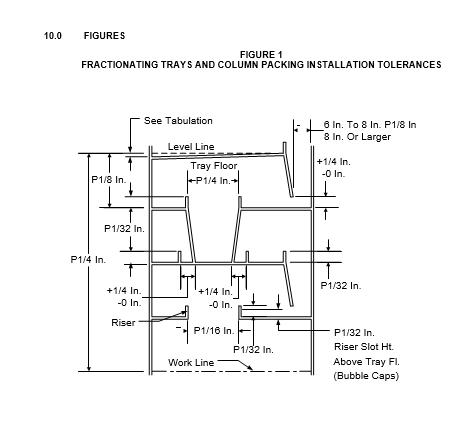
- Accumulator trays used for all vacuum columns and/or where all liquid leakage has to be avoided, shall incorporate the features for non-circular risers shown in Figure 1.
- Where rectangular risers are used, the risers shall be orientated to be parallel to the general flow of liquid across the tray.
- Accumulator tray caps shall be orientated so that liquid pouring from one cap shall not enter the vapor emergency area of an adjacent cap.
- (*)The design of a draw off tray handling two liquid phases and where one phase only is required to be removed shall be subject to approval by the Owner's Engineer.
- (*)Overflow weirs on accumulator trays shall not be provided for fouling services. The Owner's Engineer will specify when a service will be considered as fouling.
- Sieve Trays
- Sieve or perforated trays shall have 1/2 inch diameter holes.
- The maximum tolerance on the diameter of the holes shall be 0.005 inches.
- The installed unblocked hole area of sieve trays shall be within 1% of the specified hole area.
- Holes in sieve trays shall be punched, or drilled so that the punch or drill exits on the top of the finished tray. All burrs shall be removed from the tray surfaces.
- Holes shall be uniformly distributed over the entire area of the tray. An equilateral triangular pitch, for the holes, is preferred.
- Blanking shall not be used to adjust installed hole area to the specified design value.
- Deck sections shall not be perforated into the tray edge which will sit on the tray ring.
- Bubble Cap Trays
- When the bubble caps are used the design shall conform to the design of the FRI "standard bubble cap."
- When bubble caps are used they shall be securely attached using the tray fabricator's standard bolting anchors and bolts or wedges. The use of wedges is preferred.
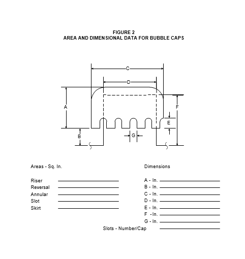
- Area and dimensional data for bubble cap trays shall be specified in accordance with Figure 2.
- Valve Trays and Other Tray Types
- Unless otherwise specified valve tray orifice covers shall be provided with a device which will permit contact with the tray floor at only two or three points in the case of circular valves or three points in the case of rectangular valves so as to prevent adherence of the valve cover to the tray floor.
- (*)The design and rating of other tray types such as baffle trays, shower decks, disc and donut, etc. must be reviewed with and approved by the Owner's Engineer.
6.12 Shipping
All component parts of assemblies shall be permanently marked with piece marks corresponding to those shown on the manufacturer's detail and assembly drawings. All like pieces shall have the same mark. Marks shall be made at the same relative location on all similar pieces.
PACKED COLUMNS
- Packing
- The supply of random packing shall be made only on the basis of filling a given column diameter to a given depth.
- The maximum depth of any packing for a single bed shall be stated by the manufacturer, but not to exceed 40 feet for random packing.
- The supplier of structured packing shall ensure that peripheral sealing and wall wiping is provided to prevent vapor bypass due to column ovality, manufacturing tolerances, etc. and to redirect liquid from the wall back to the packing.
- Distributors - Gravity
- Gravity distributors shall be provided with a means of ensuring that the parting box(s) and all the channels are capable of being levelled. Levelling shall not rely on the ability to fabricate components to the appropriate mechanical tolerance.
- For a vapor-liquid system, liquid distribution to the top of the packed bed shall be uniform over the whole design operating range. This uniformity of flow shall be maintained as the liquid impinges onto the top of the packed bed and the design of the distributor shall be such that uniformity is not affected by liquid head variations.
- The distance between the outermost liquid distribution points and the column wall shall be in accordance with paragraph 7.2.4 when random packing is used, and a maximum of 2 inches when structured packing is used.
- Random packing distributors shall have at least the discrete liquid streams per square foot of column cross-sectional area as shown in Table 4.
- Particular attention shall be given to ensure that flow from the outermost discharges are not blocked by the presence of any other piece of equipment in the column. Under no circumstances shall liquid discharge from the distributor impinge on the column wall.
- (*)The design of the distributor shall be such that the channels and parting box, or in the case of a pipe distributor the whole assembly, can be levelled to within 0.125 inch high to low or the tolerances specified by the Owner or by the manufacturer whichever is tightest.
- Liquid supply to the parting box shall be so arranged that there is negligible visible aeration of the effective liquid head when judged by hydraulic test.
- Distributor design shall be subject to a minimum orifice diameter which will be a function of the process fluid characteristics. This minimum diameter shall not be less than 0.08 inch.
- The manufacturer shall ensure that orifices shall be formed with the punch exit on the downstream side of the distributor.
- Where liquid redistribution is required the redistributer shall be of the same general design as the primary liquid distributor.
- See paragraph 8.2 for distributor testing.
- Distributors - Pressure
- Spray nozzle distributors shall be designed for a minimum coverage ratio of three (3), where the coverage ratio is defined as the ratio of the total geometrical spray footprint area to the column area. Nozzles shall be arranged so that there are no unirrigated areas. Circular full cone spray nozzles shall be used. Unless otherwise specified or agreed upon, the catalogue spray angle shall be used.
- Where ladder type distributors are selected, and where plain holes are used, care shall be taken to remove all internal burrs, etc., which would otherwise affect the liquid flowrate. Any pipe system should have a vent hole to prevent accumulation of vapor.
- Feed pipes to the distributor shall be sized to limit the maximum velocity to 5.9 feet/sec.
- For fouling services the minimum free passage through the nozzle shall be equivalent to a diameter of 0.125 inch.
- Ancillary Equipment
- All packed beds shall be provided with a hold-down grid, the design of which will be a function of the particular packing and distributor type being used. In all cases the grid design shall be such as to offer the minimum possible coverage of the packing below. In this context angle sections are not acceptable.
- Where structured packing is used, any bars constituting the hold down grid shall be orientated so that they do not lie along joints between adjacent blocks of packing.
- This requirement extends to liquid-liquid systems regardless of the interface position.
- Support plates shall be such as to impose the minimum resistance to vapor flow with an open area of at least 92.5% of the column cross-sectional area.
- Suitable external duplex filters should be considered for all gravity or pressure distributors in fouling service.
- In columns with dumped random packing there shall be an 18 inch manway, for packing removal, in the vessel wall directly above the packing support plate.
- (*)Vapor distributors may be recommended by either the manufacturer or the Owner's Engineer.
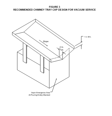
- Chimney tray caps for vacuum service should be designed according to Figure 3.
INSPECTION
- Leak Testing and Inspection
- (*)All accumulator trays shall be subject to a water leak test at site. The Owner's Engineer will specify the category of leak test to be applied (refer to Table 5).
- One tray per type, including accumulator trays, shall be assembled in the manufacturer's shop to the extent necessary to check the dimensions. The assembly shall be examined by the Inspector.
- Distributor Testing
- (*)The Owner's Engineer shall require all gravity distributors to be shop tested at the manufacturer's premises before shipment to check the hydraulic performance at maximum and minimum design flow rates. The testing shall be witnessed by the Inspector.
- (*)Manufacturer's test procedure shall be submitted to the Owner's Engineer for approval in parallel with drawing approval and shall meet or exceed the following procedures:
- Flowrate: Test shall be done at the minimum design GPM and 110% of the normal design GPM.
- Setup
- The test stand whenever possible shall include distributor and any predistribution device(s).
- Method of introduction of test fluid should be appropriate and closely mimic the installed system.
- Sufficient clearance under the distributor for visual inspection and flowrate sampling is required.
- The piping used to provide liquid to the test stand shall not be supported by the distributor or predistribution devices unless included in the design of the distributor.
Also, access to the center of the distributor is needed for liquid level measurement by the Inspector.
- Data Collection
- Measurement of liquid depth at each end and the center of each trough (for pan-type distributors measurements will be taken at a minimum of 10 representative locations).
- Liquid flowrate from various sampling locations under the distributor. Each location will include one or more drip points per Table 6.
- The flowrate should be measured a minimum of three times at each location, and arithmetically averaged.
- Ten or more separate locations should be sampled for each feed rate.
- Acceptance
- The flowrate variation should not exceed a standard deviation of 8% of the mean at either feed rate.
- The distribution pattern should not change regardless of feed rate.
- The head at minimum feed rate should not be less than 0.75 inch.
- Distributor and/or predistributor shall not overflow at the maximum feed test rate.
- Shipping
- Trays which are shop installed shall be centered on the tray rings. Prior to shipping removable spacers, supports or brackets shall be installed to prevent tray movement so that the tray centering is maintained. These devices shall be removed after the column has been erected.
- All parts shall be suitably packed and protected from damage.
- Each package shall be marked to show contents, part numbers, complete requisition number and vessel name and number. In the case of structured packing each element should be marked.
- All trays and tray parts shall be free of grease, oil, weld splatter, burrs and other foreign matter before shipping.
- All carbon steel parts shall be protected by coating with a suitable oil or rust preventative.
- Prior to shipping, one tray of each type shall be assembled in the vendor's shop. The purchaser shall be notified not less than 5 working days before the assembly date and the Purchaser's Inspector shall be given an opportunity to inspect these assemblies.
- (*)If a protective coating is used on any part, the Owner's Engineer shall be notified of the nature of the protective coating prior to its application to determine process compatibility.
- Tray parts shall be preassembled for shipping, by the tray manufacturer, to the maximum extent possible consistent with access through the column shell and tray manways and the applicable weight limits.
- Small parts, such as bolts, nuts, washers, clamps, etc., shall be adequately packed and included in the larger containers where practical. Each type of the small parts shall be packed in a separate package with its own identification.
- Two sets of the final fabrication and installation drawings shall be shipped with the trays.
- Installation Tolerances
- A high degree of workmanship shall be practiced in the installation of the trays to insure conformance with this Practice.
- All column internals where liquid tightness is required shall be leak tested after installation and shall have no leakage or be classified according to paragraph 8.1.1.
- A 90% metal to metal contact shall be achieved on all mated metal to metal joints.
- There shall be no gap, in excess of 0.25 square inches, on the installed tray where three or more tray components join.
- The maximum gap between mated surfaces shall not exceed 1/16 inch.
- All bolting used for tray installation shall be uniformly tightened, using torque wrenches, to the torque levels specified by the tray manufacturer. The required torque levels shall be specified on all installation drawings.
- (*)After the installation of internals and/or hydraulic testing, the erection Contractor shall take steps to prevent the rusting of carbon steel internals. The procedures selected shall be reviewed and approved by the Owner's Engineer.
- The trays shall be centered on the tray rings.
- Column weld-ons, trays and installation shall be within the tolerances in EP 7-2-1.
- The top of each weir plate shall be true and level with respect to a horizontal line within 1/8 inch from high to low point. If necessary, weir plate levelness takes precedence over weir height tolerance in installation.
- Packing shall be installed, after the column has been erected, in accordance with the manufacturer's instruction.
- Care shall be taken during the installation of packing to prevent crushing of the packing. Workmen shall not stand directly on the packing. Boards shall be laid on the packing to avoid concentrated loads from equipment or workmen.
9.0 TABLES
TABLE 1
RATING PROCEDURES FOR TRAYS AND PACKING
| Trays/Packing | Rating Procedure |
|---|---|
| Proprietary trays | Proprietor's Procedure (1) |
| Non-proprietary trays | Latest FRI Procedure |
| Random packing | Latest FRI Procedure or Proprietor's Procedure (1) |
| Structured packing | Proprietor's Procedure (1) |
| Proprietary packing | Proprietor's Procedure (1) |
NOTES:
(1) Proprietary rating procedures shall be made available for 's evaluation.
TABLE 2
DOWNCOMER BACK-UP CRITERIA
| System Pressure | Backup |
|---|---|
| Less than 30 psig | 60% |
| 30-100 psig | 55% |
| 101-200 psig | 50% |
| 201-250 psig | 45% |
| Greater than 250 psig | 40% |
TABLE 3
TRAY SPACING REQUIREMENTS
| Tray Type | Spacing |
|---|---|
| Normal Trays | 24 inches |
| Feed Trays | Normal tray spacing plus the diameter of the feed nozzle or 6 inches whichever is greater. |
| Above Top Tray | A minimum of 1.5 times normal tray spacing to tangent line. |
| Shell Manway Trays | Internal diameter of manway plus 6 inches or design tray spacing whichever is greater. |
| Draw Trays and Other Trays |
Spacing to be reviewed and approved by Owner's Engineer. |
TABLE 4
RANDOM PACKING DISTRIBUTOR CRITERIA
| Ring Size (inch) | Pour Points Per ft2 | Outermost Points Max. Dist. from wall (inch) |
|---|---|---|
| 5/8 1 1-1/2 2 3-1/2 |
20 12 8 7 6 |
1 1 1.5 2 3 |
TABLE 5
LEAK TEST CATEGORY
| Category | Typical Application | Max Acceptable Rate of Level Drop (in/hr) |
|---|---|---|
| 1 | Vacuum columns - Lowest distillate draw |
3/8 |
| 2 | Vacuum columns - except Category 1 |
2.0 |
| 3 | All other columns | 8.0 |
TABLE 6
DRIP POINT REQUIREMENTS
| Column Diameter (feet) | Approximate number of holes from which liquid is collected for each location |
|---|---|
| 3 or less | 1 |
| 3-6 | 5 |
| 6 or more | 10 |
© 2026 Inflection Point Engineering, LLC. All rights reserved. The content of this page — including calculation methods, reference data, written analysis, interactive tools, and source code — is the intellectual property of Inflection Point Engineering, LLC and is protected under applicable copyright, trademark, and trade secret laws. Unauthorized reproduction, redistribution, modification, or derivative use in whole or in part is prohibited without prior written consent.
Disclaimer. This material is provided for informational and educational purposes only and does not constitute professional engineering advice. Calculations, reference data, and methodologies are based on published standards and accepted engineering practice but are not a substitute for engineering judgment, site-specific analysis, or review by a licensed Professional Engineer. Inflection Point Engineering, LLC makes no warranties, express or implied, regarding the accuracy, completeness, or fitness for a particular purpose of any content presented here, and shall not be liable for any direct, indirect, incidental, or consequential damages arising from its use. Users assume all risk associated with applying this content to real-world design, operations, or decisions.
© 2026 Inflection Point Engineering, LLC. All rights reserved.