 Section 7 — Pressure Vessels
Pressure Vessel Internals
IPE Engineering Practice IPE-EP-7-2-1
Document number: IPE-EP-7-2-1 · Section: 7 — Pressure Vessels

SCOPE
- This Practice covers mandatory requirements governing the mechanical design, fabrication, and inspection of internals for all pressure vessels other than fractionating towers. The process design for all pressure vessel internals is subject to the approval of the Owner's Engineer.
- Process design and supplemental requirements for design, fabrication inspection, and testing of fractionating trays and column packings supplied by tray manufacturers are covered in EP 7-2- 2.
- The mechanical design requirements of this Practice shall be adhered to for all internals, including proprietary designs.
- This Practice does not cover internal components for heat exchangers. Requirements for these items are stipulated in EP 8-1-1.
- An asterisk (*) indicates that a decision by the Owner or Owner's Engineer is required, or that additional information is furnished by the Purchaser.
- Any deviation from this Practice must be approved by the procedure described in EP 1-1-3.
- A revision bar indicates all changes made to this Revision.
2.0 REFERENCES
The latest edition of the following standards and publications are referred to herein.
STANDARDS AND PUBLICATIONS
| IPE Engineering Practices |
|---|
| EP 1-1-3 Deviations to IPE Engineering Practices EP 7-1-1 Pressure Vessels EP 7-1-5 Welding Requirements for Pressure Vessels EP 7-1-6 Metal Lining and Cladding EP 7-2-2 Fractionating Tray and Tower Packing EP 7-2-3 FCCU Cyclones EP 8-1-1 TEMA Shell and Tube Heat Exchangers EP 10-2-1 Material Requirements for Aggressive Environmental Services EP 10-2-3 Material Hardness Requirements |
| AISC |
| Manual of Steel Construction, Eighth Edition |
| AISI |
| Cold-Formed Steel Design Manual |
STANDARDS AND PUBLICATIONS (CONT.)
| APl Publications |
|---|
| Publ 941 Steels for Hydrogen Service at Elevated Temperatures and Pressures in Refineries and Petrochemical Plants. |
| ASME Codes |
| B31.3 Chemical Plant and Petroleum Refinery Piping Sec VIII Pressure Vessels, Alternative Rules, Division 2 |
| Sec III Division 1 - Subsection NH, Class 1 Components in Elevated Temperature Service |
DEFINITIONS
- Aggressive Environmental Service (AES) - Process services which result in material degradation such as cracking, scaling, blistering, and severe pitting and/or corrosion. Examples of such services are hydrogen service, wet hydrogen sulfide, cyanides, caustic, amine, and hydrofluoric acid. AES process fluid are defined in EP 10-2-1.
- Contractor - Company or business that agrees to furnish materials or perform specified services at a specified price and/or rate to the Owner.
- Hydrogen Rich Service - A service defined as a combination of hydrogen partial pressure and temperature at or below the curve for carbon steel per Figure 1 of API Publication 941, latest edition, and with a hydrogen partial pressure greater than 100 psia.
- Hydrogen Service - A service defined as a combination of hydrogen partial pressure and temperature above the curve for carbon steel per Figure 1 of API Publication 941, latest edition.
- Inspector - A Inflection Point Engineering, LLC appointed engineer or inspector.
- Major Beams - Beams that are 10 feet and longer, or beams regardless of length that extend across a vessel without interruption. All other beams shall be considered as minor beams.
- Minor Beams - Beams that are not major beams.
- Manufacturer - The recipient of a direct or indirect purchase order for materials and/or equipment. In this context, a direct order is one issued to a manufacturer by a contractor or the Owner. An indirect order is one issued to a manufacturer by a vendor (recipient of a direct order) for materials, fabricated components, or subassemblies.
- Owner - Inflection Point Engineering, LLC.
- Owner's Engineer - A Inflection Point Engineering, LLC appointed engineer.
- Purchaser - The party placing a direct purchase order. The purchaser is the Owner's designated representative.
DOCUMENTATION
- The manufacturer's shop detail drawings shall show all fabrication details and the following data:
- Design temperature and all assumed design loads.
- Extent of ultrasonic, radiography, magnetic-particle inspection, or other nondestructive tests.
- Stress relieving and special welding procedures.
- All material specifications including bolting and gaskets.
- Actual corrosion allowance for all internals (i.e., total new metal thickness minus thickness required for strength).
- Location and fabrication details for all internals, including all tray details and method of sealing to shell.
- Details of all vents required for hydrogen service.
- All necessary instructions and piece numbers for all parts to facilitate shop or field installation.
- Additional drawing requirements for fractionating trays and column packing are stipulated in EP 7-2-2.
- (*)Two copies of design calculations made by the Manufacturer shall be furnished with or prior to submission of prints for approval. All structural design calculations for trays and internal supports shall be included. Where calculations are made on a computer, all input data, assumptions, summary of results and all output data description shall be furnished. Additionally, this information is subject to the approval of the Owner's Engineer.
- After final approval of drawings, the manufacturer shall supply the following certified data.
- Certified drawings containing all information required by paragraph 4.1.
- (*)Data reports executed in accordance with the applicable code shall be supplied to the Owner's Engineer.
MATERIALS
- Acceptable grades and specifications of materials for construction of pressure vessel internals are shown in Table 1.
- (*)Internals shall be of the same material as the interior surface of the vessel shell unless otherwise specified by the Owner's Engineer.
- (*)Additional requirements for materials, welding control, hardness limits, and heat treatment will be specified by the Owner's Engineer for internals subject to Aggressive Environmental Service.
- The Manufacturer's proposal to use alternative materials to those specified shall be submitted for approval to the Owner's Engineer.
- (*)When materials are not specified, the Manufacturer's proposals shall be submitted for approval by the Owner's Engineer.
- Free machining grades of steel are not permitted, except that AISI Type 416 nuts furnished to A 194, Gr-6F with Selenium are acceptable for use with ASTM A193 B-6 bolts.
- Bolting material shall conform to the following requirements:
- All bolting for internals shall be a minimum of 3/8-inch diameter. Bolts shall have heavy hex heads and nuts.
- All bolting hardware shall be the same type of material as the internals that they are connecting or which are being connected to support members. However, 12 Cr shall be used for unlined carbon steel vessels (with carbon steel internals) when the specified corrosion allowance for the shell is greater than 1/8 inch.
- Bolting hardware for tray manways shall be of noncorrosive material to facilitate opening for inspection and maintenance.
- Bolting, both studs and nuts, shall be marked to permit positive identification of the material.
- (*)Material for thermowells shall be per EP 7-1-1 and will be specified by Owner's Engineer. The wall thickness of thermowells shall include a corrosion allowance compatible with the corrosion allowance for the vessel shell.
- Gasket and Packing materials shall conform to the following requirements:
- Gasketing, when required, shall be non-asbestos tape products as Amatex Style G36P752, Southern Textile Style 300 or equal.
- Rope packing, when required, shall be non-asbestos rope products as Amatex Style 1 0- 786G rope, Southern Textile Style 500 rope or equal.
- Listing tape and washers shall be 1/1 6-inch thick.
- In addition to the required quantity of tray hardware (bolts, nuts, washers, clamps, etc.) for installation, the supplementary materials required by Table 3 shall be furnished.
- (*)Materials for screens and tie-wires shall be specified by the Owner's Engineer.
MECHANICAL DESIGN REQUIREMENTS
- General
- Vessel internals which result in an increase to the total vessel height shall be designed for a minimum height. In addition, similar parts shall be interchangeable where possible.
- The design of all vessel internals shall be such that all parts can be removed through the vessel manways. The design shall make allowance for the removal of internals through tray manways, from locations remote from vessel manways. The exception is for approved sections sealwelded inside the vessel.
- All internals, except shrouds, shall be removable with vertical thermowells in place, and shall be designed to pass through the nearest manhole above their level.
- All removable internals shall be designed to permit installation and removal from the top side.
- Screens shall be attached on top of grids and catalyst support hardware to prevent inert fillers and catalyst from:
- Falling through holes or slot openings.
- Blocking clearances in support hardware that are required for thermal expansion.
- In vessels to be used in Hydrogen Service or Hydrogen Rich Service, all dead spaces or voids, such as the annulus between fillet welds on slip-on flanges, preferably shall be avoided. If such voids are unavoidable, they shall be vented with a 1/8-inch diameter vent hole to prevent hydrogen pressure buildup.
- (*)If a refractory lining is required, sufficient details will be furnished by Owner's Engineer to permit design of the shroud or other internal components.
- The design of internal fittings shall ensure that they will not be subject to loosening by vibration; for example, thin baffle plates shall be welded by means of a continuous fillet weld on both sides of the baffle.
- (*)Tray support rings, downcomer clamping bars, and all other vessel attachments required for tray installation shall be designed by the tray manufacturer. They shall be furnished and installed by the vessel fabricator unless otherwise specified by the Owner's Engineer. The vessel manufacturer shall also install the tray and cap assemblies according to the tray Manufacturer's drawings.
- Design Calculations
- Internals with a structural frame type configuration with design temperatures below the creep regime for the material in question shall be designed in accordance with the AlSC Manual of Steel Construction or the AISI Cold-Formed Steel Design Manual, whichever is applicable. The design shall be based on corroded thickness at the design temperature. The yield strength and modulus of elasticity used for design shall be as specified in ASME Section VIII, Division 2 at the design temperature.
- Beam lateral stability and web crippling shall be checked per the AlSC Specifications. In addition, Part 2 of Part 5 (Plastics Design) of the AlSC Specification shall not be used to design internals unless approved by Owner's Engineer.
- (*)Internal components comprised of plate and/or shell type consturction which are outside of the scope of the standards listed in paragraph 6.2.1 shall be designed as follows. For designs in the creep regime, the proposed design procedures based on cyclic operation and component criticality shall be submitted to the Owner's Engineer for review and approval prior to commencement of design.
- Design temperatures below the creep regime - design procedures shall be in accordance with Appendix 4 and Appendix 5 of the ASME Code, Section VIII, Division 2. Allowable stress values shall be per this code.
- Design temperatures in the creep regime (allowable stresses per ASME Code, Section VIII, Division 2 are not listed), predominantly noncyclic operation and noncritical components - design procedures shall be in accordance with Appendix 4 and Appendix 5 of the ASME Code, Section VIII, Division 2. Allowable stress values shall be per ASME B31.3.
- Design temperatures in the creep regime (allowable stresses per ASME Section VIII, Division 2 are not listed), cyclic operation or critical components - design procedures shall be in accordance with the ASME Code, Section III - Division 1, Subsection NH.
- All internals fabricated from pipe at all temperatures shall be designed in accordance with ASME B31.3.
- Loads and Deflections
- Vessel internals shall be designed for the total dead and live loads which they must carry. The design load shall include the weight of catalyst or packing elements plus the weight of the process fluid when the section is operating in the fully flooded regime. The effects of eccentrically-applied loads producing torsion in the beams must be considered.
- Support members as defined in Table 2 shall be designed for a concentrated live load of 330 pounds at any point based on the allowable stress at 100F. This design shall be based on the corroded thickness of the support members; that is, the total thickness less the corrosion allowance. For internals subject to the fluid service on both sides, the design shall be based on the total thickness less twice the corrosion allowance. For maintenance loads, stresses in the tray need not be considered.
- Trays shall have a maximum deflection from the horizontal of 1/900 times the diameter at maximum operating temperature and under a uniform loading equivalent to a water level 2 inches above the top edge of the overflow weir.
- Accumulator trays shall be able to withstand a liquid load equivalent to the tray being covered with water to the height of the chimneys.
- If internal feed pipes, distributors of other internals are to be supported by the tray, the manufacturer shall be notified and shall make proper allowance in the tray design to accommodate the additional load. It is preferred, where possible, that such internals be supported from the vessel shell.
- The design of all internals shall take into account all stresses which may arise due to transient temperature/pressure conditions, post-weld heat treatment conditions, and loads due to hydraulic test conditions.
- Corrosion Allowance and Minimum Metal Thickness
- The corrosion allowance shall be added (on each "wetted" surface) to the calculated thickness of all tower attachments and to the throat dimensions of welds attaching such parts to the vessel unless such parts are made of corrosion resistant material.
- A minimum corrosion allowance of 1/16 inch shall be applied to all surfaces of carbon steel trusses and beams.
- A minimum corrosion allowance of 1/16 inch shall be added to the thickness of carbon steel trays.
- No corrosion allowance shall be provided for alloy parts (beams, trusses, tray decks, etc.) unless specified.
- The minimum fabricated thickness, including corrosion allowance, shall be as shown in Table 2.
- The minimum Thickness of Tower Packing shall be as shown in Table 4.
- Supports Welded to the Vessel (Internal Tower Attachments)
- Supports to be welded to the vessel shall be designed such that all localized stresses comply with the applicable ASME Code.
- Support rings, downcomer clamping bars and all other attachments required for installation of fractionating trays shall be designed by the tray manufacturer. The attachments designed by the tray manufacturer shall be fabricated and installed by the vessel Manufacturer unless specifically ordered otherwise.
- (*)The drawings of the support rings, downcomer clamping bars and other attachments made by the manufacturer shall be submitted to the vessel Manufacturer and the Owner's Engineer for review and approval. Tray or other internals drawings shall not be considered to be approved until such review has been completed and approval confirmed in writing.
- Support rings for vessels 15 feet in diameter and larger shall be provided with gusset braces on no less than 3 foot centers in order to maintain level support rings. Smaller vessels shall have gusset braces beneath the tray support rings if, in the opinion of the Manufacturer, they are required.
- Support rings, downcomer bolting bars, internal clips and brackets, etc. shall be the same material as the vessel in unlined vessels and the same material as the vessel lining in clad vessels unless otherwise noted on the vessel design drawings.
- When the tray support ring material differs from the shell material, the effects of differential thermal expansions shall be checked by the manufacturer. In the event of excessive thermal stress, the tray support rings shall be slotted and reinforced as necessary.
- The minimum width of support rings shall be as shown in Table 5.
- Bolted and Clamped Connections
- Connections shall be designed in accordance with the AISC Manual of Steel Construction or the AISI Cold Formed Steel Design Manual, whichever is applicable.
- Adequate clearances (slotted holes) shall be provided at bolted connections which must accommodate thermal expansion.
- Joints between the tray deck and the support ring shall be "clamp type" with through bolting; threaded extruded holes in clamps shall not be used. The clamped joint shall allow for thermal expansion at all temperatures from ambient to design temperature.
- Support member connections, and the top piece of the downcomer-to-bolting-bar joints shall be through bolted joints.
- Wedge type tray and bubble cap hold downs are not permissible.
- The number of different bolt diameters utilized in the construction of internals shall be minimized for each vessel. When more than one bolt diameter is used, the bolts shall be paint marked for easy identification of bolt diameter.
- The maximum center-to-center spacing of clamps or bolts shall be 6 inches, whether or not gasketing or packing is used.
- Additional Requirements for Liquid Trays
- The weight of the individual parts of components which are normally disassembled such as tray decks, downcomers, distributor piping, baffles, minor beams, etc. shall not exceed 65 pounds (including attached vapor-liquid contacting devices). The weight of tray manways shall not exceed 50 pounds.
- Tray, weir and downcomer joints shall be bolted or clamped tight. Joints of sections with a total thickness of 3/16 inch or less shall be overlapped to insure tightness.
- Like parts shall have the same tolerances and shall be interchangeable. Symmetrical layouts shall be used, where possible, to reduce the number of different parts.
- Tray details, including tray support beams, shall be designed to suit the size of the vessel, operating loads and operating temperatures. All trays shall safely support the loads necessary for installation and maintenance of the column internals as well as process and mechanical roads indicated on vessel drawings or rating calculations or as defined in Section 5.3.
- (*)Where liquid tightness is required for specific vessel internals such as draw pans, draw trays, distributor pans, seal pans, etc., the contractor or tray manufacturer shall submit their proposed design to Owner's Engineer for approval. No internal requiring liquid tightness shall be ordered without prior written approval by Owner's Engineer. The general design concept for these internals shall be included with any quotation.
- Seal welding of the tray or pan deck to the tray ring or vessel is not acceptable except at the point where there is an external draw nozzle for the tray or where differential expansion and stress analysis has shown no problem. Seal welding of the deck sections of a tray is permitted.
- The minimum liquid flow path between the downcomer escape and the overflow weir shall be18 inches.
- Where threaded tray clamps extend up through tray floors, screwdriver slots shall be provided in the tops to permit positioning during tightening.
- Tray assemblies shall be designed to accommodate a column out-of-roundness of 1% of column internal diameter.
- Requirements for Tray Support Beams
- Major beams shall be installed parallel to the direction of liquid flow on the tray below the beam.
- Major beams shall not be supported by or attached to downcomer panels.
- Beams extending completely across a vessel shall not be welded in place. Provision for thermal expansion, between the vessel shell and the beam, shall be made at the point of attachment at the shell. All major beams shall be restrained against vertical and horizontal movement which may occur during process upsets.
- Methods of attachment which rely on indirect fastenings are not acceptable.
- Minor beams installed perpendicular to the direction of liquid flow shall have a depth no greater than 25% of the tray spacing.
- Beams installed parallel to the direction of liquid flow shall be a minimum of 6 inches or overflow weir height plus overflow weir liquid crest, whichever is greater, above the tray deck.
- The distance between the upper edge of an accumulator tray riser cap and the underside of tray or packing support shall be at least 14 inches.
- The manufacturer shall ensure that the structural members above the riser caps of accumulator trays do not obstruct the flow of vapor from the risers. Such members shall be orientated so that they are parallel to, and whenever possible, immediately above the riser caps.
- Orifices shall be provided in the webs of the beams to promote crossflow.
FABRICATION REQUIREMENTS
- General
- To facilitate rapid assembly, all internals shall be marked to correspond with the markings provided on assembly drawings.
- Non-leaded paint shall be used for marking.
- The surface finish of all internals shall be in accordance with the following requirements:
- Surfaces of fabricated parts shall be smooth and free of dents, hammer marks, kinks and other defects, particularly in locations which might prevent close metal-to-metal fit.
- Edges of all surfaces shall be free of burrs.
- Edges of tray accessways shall be beveled or rounded for safety.
- All welds shall be smooth and free from slag and splatter.
- Welding
- Weld design, welding procedures and heat treatment requirements shall be in accordance with EP 7-1-5.
- All internals other than tray support rings and downcomers welded to the vessel shall be attached with full-penetration welds. Tray support rings and downcomers shall be attached to the shell with a continuous full fillet weld on the top side and a seal weld or continuous full fillet (if required for strength) on the under side; stitch welding is not permitted. However, for vessels in Hydrogen Service or Hydrogen Rich Service, tray support rings shall be attached to the shell using a full penetration weld.
- (*)Attachment details for internals welded to strip lined, clad or overlayed vessels shall be per EP 7-1-6.
- (*)For items that cannot be completely shop fabricated, the manufacturer shall submit for approval by Owner's Engineer design drawings clearly designating field welds, post-weld heat treatment, and nondestructive testing required.
- When possible, attachments to vessel wall shall be located to avoid conflicts with weld seams.
- The postweld heat treatment sequence for vessels with welded internal attachments shall be as specified in EP 7-1-1.
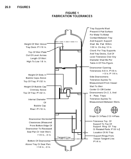
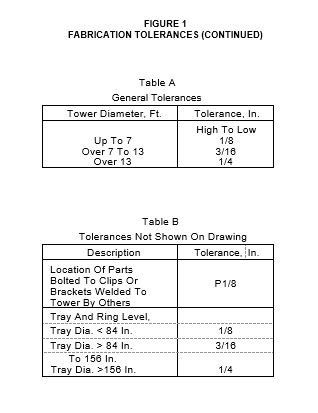
7.3 Tolerances
Fabrication tolerances for pressure vessel internals shall be in accordance with Figure 1.
THERMOWELLS
- Thermowells shall be designed to resist collapse due to external pressure, or other loads, in the fully corroded condition.
- The clearance between thermowell and thermowell nozzle shall be minimized.
- Side entering thermowells shall be structurally supported within the vessel.
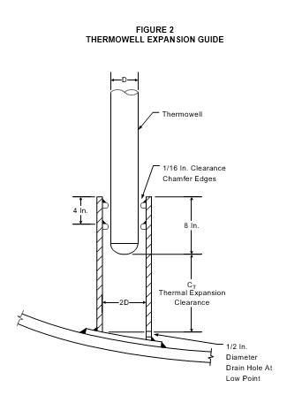
- (*)Expansion guides, per Figure 2, shall be provided for all vertical thermowell installations. The thermal expansion clearance (CT ) will be specified by the Owner's Engineer.
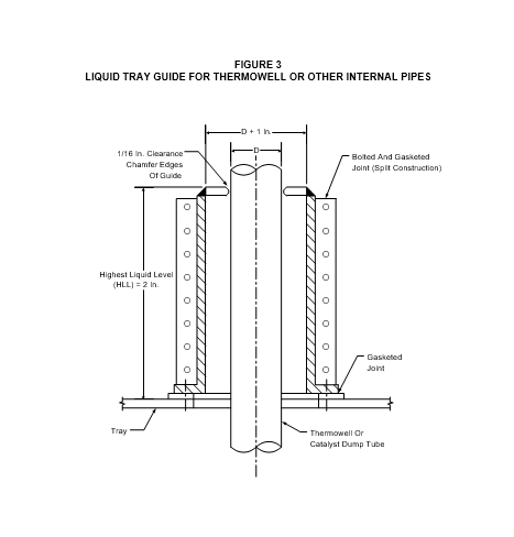
- (*)Tray guides, per Figure 3, shall be provided to minimize liquid leakage at points where thermowells pass through trays. The highest liquid level (HLL) will be specified by the Owner's Engineer.
- (*)Openings to permit thermowells to pass through other internals shall be sealed; the design of seals shall be approved by Owner's Engineer.
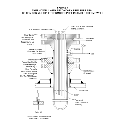
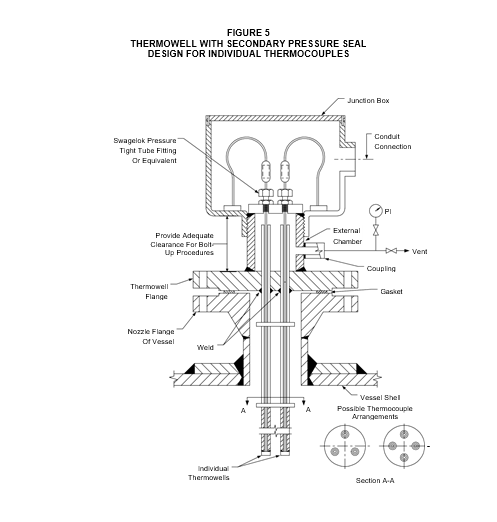
- (*)Unless otherwise specified, secondary seal thermowells per Figure 4 and Figure 5 shall be used with all fixed bed reactors. Alternative secondary seal thermowell designs require approval of the Owner's Engineer.
- In the Figure 4 design, the thermowell shall be designed for maximum external and internal pressure. Twice the specified vessel corrosion allowance shall be applied to the wall thickness of the thermowell.
- In the Figure 5 design, the individual thermowells shall be designed for maximum external pressure and the external chamber is designed for maximum internal pressure. The specified vessel corrosion allowance shall be applied to the wall thickness of the thermowell and the wall thicknesses of the external chamber components.
- For stainless steel thermowells, a bimetallic weld is required between the thermowell and the thermowell flange. Alternatively, the thermowell flange can be specified as stainless steel and a bimetallic bolted joint can be utilized. The choice of one of these alternatives is subject to the approval of the Owner's Engineer.
- The silver solder joint between the thermocouple and seal plate of the design shown in Figure 4 is to be used when thermocouple spacing is inadequate to permit utilization of pressure tight threaded fittings. The soldered joint is acceptable for temperatures up to 650F. A welded joint is acceptable if the weld procedure ensures that burn-through of the thin walled thermocouple can be prevented during welding and that the thermocouple will not be damaged during welding.
INTERNAL PIPES AND PIPE DISTRIBUTORS
- Internal piping shall be the same nominal alloy as the inside surface of the vessel. Thickness requiremeents for piping are covered in Table 2 .
- (*)Internal flanges shall be ASME/ANSI Class 150 weld neck or slip-on type unless otherwise specified by the Owner's Engineer. Designs for internal flanges fabricated from plate material are subject to the approval of the Owner's Engineer. Internal flanges shall be of a compatible metallurgy with the material specified for the internal pipe. Internal flange bolting shall be securely tightened, and the bolt heads and nuts shall be tack welded to prevent loosening.
- When an internal distributor or sparger is of the "bayonet" type, the external flange shall be marked in such a manner that the position of the slots or holes will be known from the outside of the vessel.
- (*)Tray guides per Figure10 shall be provided to minimize liquid leakage at points where internal pipes pass through trays. The highest liquid level (HLL) shall be specified by the Owner's Engineer.
- Openings to permit internal pipes to pass through other internals shall be sealed; the design of seals shall be approved by Owner's Engineer.
LIQUID DISTRIBUTOR TRAYS, QUENCH AND SPLASH DECKS
- The nominal diameter of trays, decks, and grids shall be determined to the nearest 1/4 inch per the following:
Diameter = Vessel ID - [1% Vessel ID + 3/4 inch]
- A minimum of 3/4 inch overlap under the most adverse operating conditions shall be provided between the support ring and the OD of trays, decks, and grids.
- Bolt hole spacing around the edge of tray, deck, or grid sections shall not exceed 6 inches.
- Access through grids, decks, and trays shall be provided either by split construction or by use of manways, as follows:
- Internal manways shall provide a minimum rectangular opening of 15 x 18 inches except as provided in subparagraph 2 below.
- Access through liquid distributor trays shall be at least 2 feet wide, and of sufficient length to permit catalyst leveling and arrangement of the inert ball layer at the top of each bed by a man lying on the tray; a maximum reach of 3 feet from the edge of any opening may be assumed for design purposes to meet this requirement.
- (*)Accesses and internal manways at all levels shall be vertically aligned unless otherwise specified by the Owner's Engineer.
- Tray or deck areas blanked by supporting members shall not exceed 3 inches in width for minor beams and support rings, and 8 inches in width for major beams.
- For trays or decks requiring liquid drainage, drain holes of 1/2-inch diameter shall be provided as shown in Table 6.
- Holes in perforated trays shall be punched in the direction of flow.
- Requirements for support beams of liquid distributor trays, quench decks and splash decks shall conform to the following:
- The maximum depth of solid beam (not open truss type) tray and baffle supports perpendicular to the liquid flow on the tray below shall not exceed:
- 2-1/2 inches for tray spacing of 18 inches.
- 20% of the vertical tray spacing for trays spacing greater than 18 inches.
- Designs which utilize support beams integral with deck plates are preferred.
- (*)Support beams or trusses may be cambered subject to the approval of the Owner's Engineer. Camber shall not exceed the deflection due to dead load and shall be shown on the manufacturer's drawings.
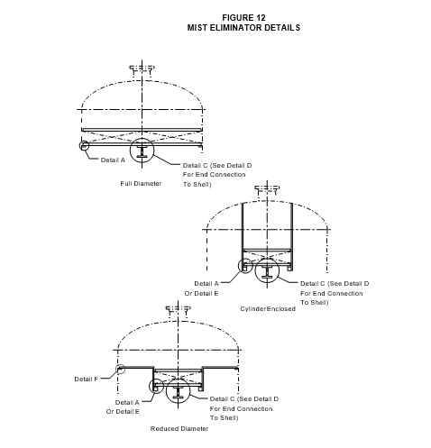
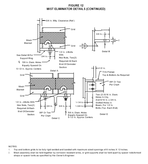
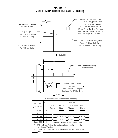
MIST ELIMINATORS
- (*)Wire mesh mist eliminators shall be of the sandwich type consisting of entrainment mesh, retained between welded grid supports as shown in Figure 12. The sandwich shall be held together by corrosion-resistant wires, or the grid supports shall be held apart by spacer rods passing through the mesh, or by formed straps welded to the top and bottom grids, or spacer bolts as specified by Owner's Engineer. Materials for the supports, rods, straps, or bolts shall be at least equivalent in terms of corrosion resistance to the other vessel internals. Support and hold-down grids shall have maxmum-sized openings of 6-inches x 12-inches. Spacer rods shall be 1/4-inch diameter and located on a maximum spacing of 12 inches.Figure 12
- (*)Unless other specified by the Owner's Engineer, the mesh for mist eliminators shall be 6 inches thick and knitted from 0.012 0.002-inch diameter wire. Material shall be AISI Type 304 stainless steel, Monel or Inconel 600. Mesh weight shall be 5 to 10 pounds per cubic foot. Proposals to use plastic mesh (e.g., polypropylene or polyethylene) shall be submitted to Purchaser for approval by Owner's Engineer.
- (*)The screen assembly shall be attached to the support beams at a minimum of four (4) points per panel with 1/2-inch minimum diameter J-bolts with locknuts. Other methods of attachment must be approved by the Owner's Engineer.
- (*)Other types of mist eliminators are chevron style, fiber bed, structured packing. Specific application of mist eliminators other than wire mesh must be approved by the Owner's Engineer.
- (*)For vessel support and mist eliminator grid design, a pressure drop of 0.5 psi shall be used unless otherwise specified by the Owner's Engineer.
FOR CATALYST BEDS SUPPORT GRIDS
- (*)Unless otherwise specified by the Owner's Engineer, bed support beams and grids shall have a minimum open area of 65 percent. The largest clearance for openings that can have direct contact with the inert balls shall not exceed 70 percent of the diameter of the balls. The clear dimension of support grid openings in at least one direction shall be no greater than 1-1/2 inches.
- (*)Unless otherwise specified by the Owner's Engineer, bed support grids for catalyst beds shall be covered by two layers of AISI Type 321 Stainless Steel 3-mesh, 0.054-inch wire diameter screen, followed by one layer of AISI Type 321 Stainless Steel 8-mesh, 0.028-inch wire screen. All three layers of screen shall extend a minimum distance of 3 inches up the web section of the support beams and the vessel shell. Screen installation shall be: first layer, 3- mesh screen; second layer, 3-mesh screen; and third layer (top), 8-mesh screen.
- (*)Profile wire screen meeting the following requirements may be proposed as an alternative to conventional support grid and wire screen construction. Mechanical designs using profile wire screen shall be submitted for approval by the Owner's Engineer.
- It shall have a nominal gap between wires equal to one-half the least dimension of the catalyst and a minimum gap of 1/32 inch.
- It shall provide a minimum open area of 20 percent.
- Design requirements for grid support beams shall conform to the following:
- Grid support beams shall be fabricated "T" sections with the flanges downward and webs intruding into the catalyst bed. The beam flanges shall be used to support bed grids and screens.
- Support beams shall be bolted to set pads or clips using slotted oversize holes to permit thermal expansion. Nuts shall be installed "hand-tight," with provisions to prevent subsequent loosening.
SHROUDS
- (*)Shroud designs, and the attachment detail to the vessel shall be submitted to Purchaser for approval by Owner's Engineer and shall conform to the following criteria:
- The shroud-to-head or shroud-to-shell connection shall be designed to minimize stresses resulting from differential thermal expansion.
- Shrouds shall be continuously welded.
- Holes in shrouds are not permitted.
- Provision must be made to purge gas from the space between the vessel lining and the back of the shroud.
- (*)When castable lining is used, the shroud (except the support ring) shall be installed after castable dryout has been completed and accepted by Owner's Engineer.
- Shroud joints shall be full-penetration butt-welded using backing strips, except that "orange- peel" joints of shroud in bottom heads may be lap welded.
OUTLET COLLECTORS
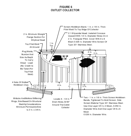
- (*)Outlet collector construction shall be one of the following types. All outlet collector designs shall be submitted for approval by Owner's Engineer.
- The design shown in Figure 6. In this design, the web between slots shall be analyzed for both top and side loadings.
- (*)A design which utilizes profile wire screen which has a nominal gap equal to one-half the least dimension of the catalyst and a minimum gap of 1/32 inch. The minimum open area will be specified for the individual application. Mechanical designs using this construction shall be submitted to the Owner's Engineer for approval.
- (*)A design made from perforated pipe components with a wire mesh screen. Mechanical designs using this construction shall be submitted to the Owner's Engineer for approval.
- (*)The design pressures acting on outlet collectors shall be specified by the Owner's Engineer. The design pressure shall be established by considering the dead weight loading of the catalyst and a differential pressure drop. This pressure drop shall include effects of increased pressure drop associated with catalyst plugging of the outlet collector screen.
- (*)All outlet collector design shall be analyzed for structural stability. A factor of safety of 3.0 shall be used in the design. Structural stability or buckling calculations are subject to the approval of the Owner's Engineer.
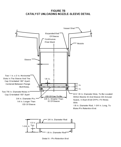
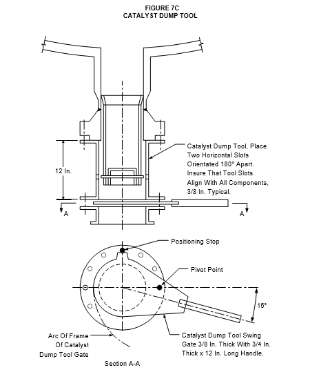
CATALYST UNLOADING NOZZLE
- (*)Unless otherwise specified by the Owner's Engineer, catalyst unloading nozzles shall be provided for all fixed bed reactors.
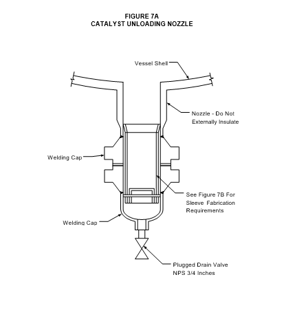
- (*)The design of the catalyst unloading nozzle and the catalyst dump tool which facilitates catalyst unloading, shall be in accordance with Figure 7A, Figure 7B and Figure 7C. Alternative designs for catalyst unloading nozzles are subject to the approval of the Owner's Engineer.
- Catalyst unloading nozzle shall be packed with mineral wool fiber prior to catalyst loading. The mineral wool fiber shall extend to the outside surface of the catalyst bed.
- Catalyst unloading nozzles shall not be externally insulated.
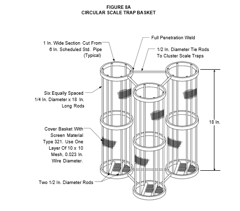
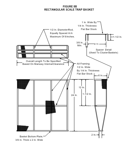
SCALE TRAP BASKETS
- (*)Unless otherwise specified by the Owner's Engineer, scale trap baskets shall be in accordance with the designs shown in Figure 8A and Figure 8B.
- Scale trap baskets may be used individually or clustered together to facilitate catalyst loading.
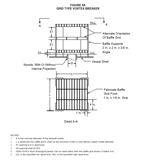
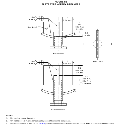
VORTEX BREAKERS
- The design of vortex breakers shall be in accordance with Figure 9A and Figure 9B.
- (*)Alternative designs for vortex breakers are subject to the approval of the Owner's Engineer.
BAFFLE AND WEAR PLATES
- (*)Designs for baffle and wear plates to be used with tangential nozzles for atmospheric and vacuum pipestill columns shall be submitted to the Owner's Engineer for approval.
- Baffle plate and wear plate material shall be of the same nominal composition as the interior shell surface.
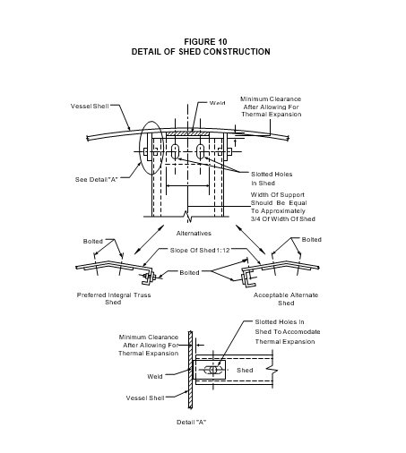
SHEDS AND SHED TROUGHS
- Sheds and shed troughs shall have their unsupported edges stiffened by an integral or bolted member as shown in Figure 10. This stiffening member shall be through-bolted to vessel shell clips or other supporting members with sufficient clearance for thermal expansion. Hold down clamps in lieu of through-bolting are not permitted for sheds or shed troughs.
- (*)Alternative designs for sheds and shed troughs are subject to the approval of the Owner's Engineer.
INTERNAL VESSEL FLOATS
- In vessels equipped with an internal float of any kind, each connection at the bottom of the vessel shall be protected with a guard designed to prevent a loose float from lodging over the nozzle opening.
- (*)Details for internal vessel floats shall be submitted to the Owner's Engineer for approval.
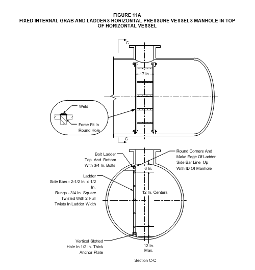
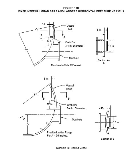
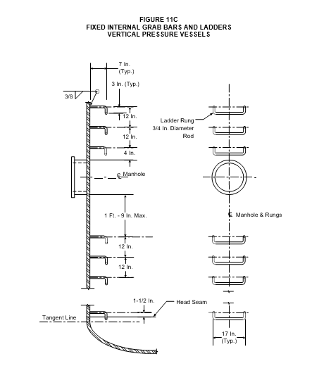
LADDERS
- (*)Fixed internal ladders and grab bars shall be provided when specified by the Owner's Engineer, in accordance with details shown in Figure 11A, Figure 11B and Figure 11C. All ladders shall be 17 inches wide, with rungs on 12-inch spacing.
- (*)Alternative ladder designs are subject to the approval of the Owner's Engineer.
- The Manufacturer shall verify that the design and location of all ladders satisfy OSHA requirements for safe vessel entry.
- Ladder design loads shall be in accordance with paragraph 6.3.2.
FCCU INTERNALS
- Design requirements for FCCU reactor and regenerator cyclones are described in EP 7-2-3.
- (*)The design for plenum chambers, air distributor pipes or grids, risers, and cyclone systems shall be submitted for approval to the Owner's Engineer. A load histogram describing pressure and temperature cycles for the start-up, normal operating, and upset conditions shall be developed by the Owner's Engineer and included in all design specifications for FCCU internals.
- The design stress basis for all FCCU internals shall be in accordance with the ASME Code, Section III - Division 1, Subsection NH.
INSPECTION AND REJECTION
- Inspection
- All materials, fabrication, and packaging shall be subject to inspection by the Purchaser during all stages of manufacture.
- All shop drawings shall be available to the inspector at the time of inspection.
- One tray, grid, and deck of each diameter and type shall be assembled in the vessel at the fabricator's shop to the extent necessary to verify fitup.
- The shroud support ring-to-reactor head or shell welds shall be 100 percent examined by the magnetic particle method from both sides of the shroud prior to vessel post weld heat treatment (PWHT). After PWHT, the welds shall be 100 percent ultrasonically examined from the outside surface of the reactor head or shell.
- Shroud joints shall be 100 percent examined by liquid penetrant; test fluids shall be chloride free. In addition, all shroud welds shall be vacuum box tested.
- Magnetic particle, Ultrasonic, and Liquid Penetrant examination and acceptance criteria shall be per EP 7-1-1.
- Material hardness shall be per EP 10-2-3.
- Rejection
Materials containing defects, completed trays and parts of trays or vessel internals having improper fabrication or excessive repairs, or components that are not in complete compliance with the requirements of the Purchase Order will be rejected. Compliance with the Purchase Order will be determined by the Inspector.
MARKING, PACKAGING, AND SHIPPING
- Marking for pressure vessel internal components shall conform to the following requirements:
- Each tray part shall be piece-marked for identification during assembly. Like pieces shall have the same piece mark.
- Bolting shall be marked in accordance with Paragraph 5.7.4.
- Paint for marking ferritic, austenitic, and high nickel alloy parts shall not contain substances (e.g., metallic pigments, sulfur, or chlorides) which could be harmful to the materials at ambient or elevated temperatures.
- Packaging and Shipping for pressure vessel internal components shall conform to the following requirements:
- The component manufacturer shall be responsible for suitably packaging all parts to protect them from damage or loss during handling and shipment and to meet any special requirements or storage conditions specified in the Inquiry.
- All parts shall be clear of debris, thoroughly clean, and free of any dirt and foreign matter before preparation for shipment.
- All carbon steel and low alloy parts shall be coated with a light coat of oil or an easily removable non-sulfur, non-arsenic-bearing rust preventatives.
- (*)Austenitic stainless steel equipment and components shall never be exposed to wetting by salt water or salt spray. Protective coatings or coverings used to prevent such exposure shall be approved by the Owner's Engineer.
- All packaging and protective material shall maintain its integrity and perform its intended function through all phases of handling, transport, and storage.
- Each package or crate shall be durably marked with the receiving address, Purchase Order Number and the vessel item number in which the trays are to be installed.
- Package markings shall be in the English language.
- Internal parts for different vessels shall not be intermixed in the same package.
- Small parts such as bolts, nuts, clamps, washers, and gaskets shall be placed in separate waterproof containers and properly identified in accordance with Paragraph 24.2.6. Different types of bolting material shall not be placed in the same container.
- The Manufacturer shall provide any special protection or packaging and details of any storage or maintenance instructions which are not within the scope of the Purchase Order, but which pertain to the Manufacturer's guarantee or warranty.

TABLE 2
MINIMUM METAL THICKNESS OF INTERNALS, INCLUDING CORROSION ALLOWANCE
| Type of Internal | Vessel Materials (1) | Vessel Materials (1) | Minimum Thickness of Internal | Minimum Thickness of Internal | Minimum Thickness of Internal | Minimum Thickness of Internal |
|---|---|---|---|---|---|---|
| Type of Internal | Vessel Materials (1) | Vessel Materials (1) | Vessel Shell Corrosion Allowance | Vessel Shell Corrosion Allowance | Vessel Shell Corrosion Allowance | Vessel Shell Corrosion Allowance |
| Type of Internal | Shell | Internals | □1/16 in. | 1/8 in. | 3/16 in. | 1/4 in. |
| Non-Supporting Members, such as: Trays, Decks,Integral Minor Beams | CS | CS | 0.134 in. | 0.179 in. | 0.224 in. | .312 in. |
| CS | Alloy | 0.075 in. | 0.075 in. | 0.075 in. | 0.075 in. | |
| CS/Alloy(2) | Alloy | 0.075 in. | 0.075 in. | 0.075 in. | 0.075 in. | |
| Alloy | Alloy | 0.134 in. | 0.179 in. | 0.224 in. | ||
| Tray Accessories such as: Bubble Caps, Chimneys, Weirs, Baffles, Vortex Breakers | CS | CS | 0.060 in. | 0.134 in. | 0.179 in. | .312 in. |
| CS | Alloy | 0.060 in. | 0.060 in. | 0.060 in. | 0.060 in. | |
| CS/Alloy(2) | Alloy | 0.060 in. | 0.060 in. | 0.060 in. | 0.060 in. | |
| Alloy | Alloy | 0.060 in. | 0.105 in. | 0.179 in. | .312 in. | |
| Internal Piping (non-pressure) | CS | CS | Sch STD | Sch STD | Sch XS | Sch XS |
| CS | Alloy | Sch 10 | Sch 10 | Sch 10 | Sch 10 | |
| CS/Alloy(2) | Alloy | Sch 10 | Sch 10 | Sch 10 | Sch 10 | |
| Alloy | Alloy | Sch STD | Sch STD | Sch STD | Sch XS | |
| Supporting Members such as: All Major Beams and Non-Integral Minor Beams; Trusses; Inlet Distributors; Out let Collector Rings; any Load Bearing Components welded to the shell. |
CS | CS | 3/8 in. | 1/2 in. | 5/8 in. | 3/4 in. |
| CS | Alloy | 3/8 in. | 3/8 in. | 3/8 in. | 3/8 in. | |
| CS/Alloy(2) | Alloy | 3/8 in. | 3/8 in. | 3/8 in. | 3/8 in. | |
| Alloy | Alloy | 3/8 in. | 1/2 in | 5/8 in. | 3/4 in. |
NOTE:
- Abbreviations used in the above table are: CS-designates carbon, low alloy and intermediate alloy steels; Alloy - designates stainless steels (300 and 400 series), Nickel alloys, Copper Alloys, Aluminum alloys.
- Interior surface of shell has an alloy cladding or weld overlay resistant to corrosion (CA=0.0) resulting from the process environment.
TABLE 3
SUPPLEMENTARY MATERIAL QUANTITIES
| Parts | Additional Per Cent Of Total Required |
|---|---|
| Bolts, Nuts, Washers Tray Clamps Gaskets, Packing |
5% 2% 10% |
TABLE 4
MINIMUM THICKNESS OF TOWER PACKING
| Packing Type | Carbon Steel | Alloy |
|---|---|---|
| Random Packing | not permitted | 0.025 inches (1) |
| Structured Packing | not permitted | Manufacturers Standard (2) |
| Grid Packing | not permitted | Manufacturers Standard (2) |
NOTES:
- Vendor may request variance from this Refining Practice.
- (*)Subject to the approval of the Owner's Engineer.
TABLE 5
MINIMUM WIDTH OF SUPPORT RINGS
| Vessel Inside Diameter (feet) | Support Ring Width (inches) |
|---|---|
| 3 and under | 1-1/2 |
| Over 3 to 6 | 2 |
| Over 6 to 10 | 2-1/2 |
| Over 10 to 15 | 3 |
| Over 15 | 3-1/2 |
TABLE 6
DRAIN HOLE REQUIREMENTS
| Tray or Deck Area (ft2) | Number of Drain Holes Per Tray |
|---|---|
| < 30 | 1 |
| 30 to 100 | 2 |
| 100 | 3 |
© 2026 Inflection Point Engineering, LLC. All rights reserved. The content of this page — including calculation methods, reference data, written analysis, interactive tools, and source code — is the intellectual property of Inflection Point Engineering, LLC and is protected under applicable copyright, trademark, and trade secret laws. Unauthorized reproduction, redistribution, modification, or derivative use in whole or in part is prohibited without prior written consent.
Disclaimer. This material is provided for informational and educational purposes only and does not constitute professional engineering advice. Calculations, reference data, and methodologies are based on published standards and accepted engineering practice but are not a substitute for engineering judgment, site-specific analysis, or review by a licensed Professional Engineer. Inflection Point Engineering, LLC makes no warranties, express or implied, regarding the accuracy, completeness, or fitness for a particular purpose of any content presented here, and shall not be liable for any direct, indirect, incidental, or consequential damages arising from its use. Users assume all risk associated with applying this content to real-world design, operations, or decisions.
© 2026 Inflection Point Engineering, LLC. All rights reserved.