 Section 7 — Pressure Vessels
Design Specification for Low Chrome
IPE Engineering Practice IPE-EP-7-1-8
Document number: IPE-EP-7-1-8 · Section: 7 — Pressure Vessels
SCOPE
- This specification provides supplemental requirements for the materials, design, fabrication, welding, inspection, testing, documentation, and shipment preparation of pressure vessels and heat exchangers in high temperature hydrogen service constructed of low chrome alloys.
- Pressure vessels covered by this Specification shall be designed, fabricated, inspected, and tested to the ASME Boiler and Pressure Vessel Code, Section VIII, Division 1 or Division 2. For vessels constructed to Division 1, paragraph references are made directly. Corresponding paragraph references to the ASME Code for vessels constructed to Division 2, when applicable, are contained within parentheses. All questions and discrepancies regarding the use of the ASME Code and its interaction with this Specification shall be resolved by the Owner’s Engineer.
- Any conflict between this specification, and any attachment, publication, code or standard is to be brought to the attention of the Owners Engineer in writing for clarification prior to any action by the vessel fabricator. In all cases, the most stringent requirement shall govern until written clarification is provided by the Owners Engineer.
2.0 REFERENCES
The latest edition of the following standards and publications are referred to herein.
STANDARDS AND PUBLICATIONS
| ASME Codes |
|---|
| Sec II Material Specifications Sec V Non–Destructive Examination Sec VIII Pressure Vessels, Division 1 Sec VIII Pressure Vessels, Alternative Rules, Division 2 Section IX Welding Qualifications B16.20 Metallic Gaskets for Pipe Flanges B16.47 Large Diameter Steel Flanges B16.5 Pipe Flanges and Flanged Fittings B16.9 Factory-Made Wrought Steel Buttwelding Fittings |
| ASCE |
| 7-95 Minimum Design Loads for Buildings and Other Structures |
| API Publications |
| RP 934 Materials and Fabrication Requirements for 2-1/4Cr-1Mo and 3Cr-1Mo Steel Heavy Wall Pressure Vessels for High Temperature, High Pressure Hydrogen Service Publ941 Steels for Hydrogen Service at Elevated Temperatures and Pressures in Petroleum Refineries and Petrochemical Plants. |
STANDARDS AND PUBLICATIONS
| NACE |
|---|
| RP0472–95 Methods and Controls to Prevent In–Service Environmental Cracking of Carbon Steel Weldments in Corrosive Petroleum Refining Environments |
| TEMA |
| Standards of Tubular Exchanger Manufacturer’s Association |
DEFINTIONS
- Aggressive Environmental Service (AES) - Process services which result in material degradation such as cracking, scaling, blistering, and severe pitting and/or corrosion. Examples of such services are hydrogen service, wet hydrogen sulfide, cyanides, caustic, amine, and hydrofluoric acid.
- ASME Code - Refers to the ASME Boiler and Pressure Vessel Code, Section VIII, Division 1 or Division 2, as applicable.
- Certified Material Test Report (CMTR) - A document, or documents, on which are recorded the results of tests, examinations, repairs, or treatments required by the Material Specification. Supplementary or special requirements, in addition to the requirements of the Material Specification, as required by the Purchase Order shall also be included on the CMTR. The specification of the material being represented including the year of issue and the material heat number shall also be included on the CMTR. All such documents shall identify the applicable Material Specification and shall be identified to the material represented.
- Contractor - Company or business that agrees to furnish materials or perform specified services at a specified price and/or rate to the Owner.
- Hydrogen Service - A service defined as a combination of hydrogen partial pressure and temperature above the curve for carbon steel per Figure 1 of API Publication 941, latest edition.
- Inspector - A Coastal Petroleum appointed engineer or inspector.
- Manufacturer - The recipient of a direct or indirect purchase order for materials and/or equipment. In this context, a direct order is one issued to a manufacturer by a contractor or the Owner. An indirect order is one issued to a Manufacturer by a vendor (recipient of a direct order) for materials, fabricated components, or subassemblies.
- Owner – Coastal Petroleum
- Owner’s Engineer - A Coastal Petroleum appointed engineer.
MATERIALS
- General
- All materials used in the manufacture of pressure vessels in hydrogen service shall be in accordance with Section II of the ASME code and the following requirements. The use of castings or reclaimed materials is prohibited.
- Unless otherwise specified by the Owner’s Engineer, materials for pressure vessel construction shall be in accordance with Table 1 and Table 2. Material substitutions shall not be made without written approval from the Owner’s Engineer.
- The use of Enhanced 2-1/4Cr-1Mo (formerly known as Code Case 1960 Material) requires Owner’s Engineer approval. This material has experienced poor performance in laboratory tests in hydrogen service.
- The use of Advanced 2-1/4Cr-1Mo-V and 3Cr-1Mo-V steels is acceptable where needed or cost effective and API 934 shall be used as a reference for materials testing and acceptance criteria.
- Plate made of 1-1/4 Cr – ½ Mo, Class 2 material shall not be used over 750oF.
- When butt weld nozzle designs (see Figure 1) are specified, the nozzle butt welding ends shall be contoured to match the curvature of the vessel head.
- Heat Treatment
- All vessel shell plates are to be normalized or quenched and tempered (See Table 1) prior to fabrication. All vessel heads are to be normalized in the formed condition. This can be done by either of the following methods:
- Hot form the head and then reheat the formed head for normalizing.
- Form the head above normalizing temperature and then allow it to normalize in the formed condition. If this method is chosen, the head manufacturer must provide proof that the head is still at or above normalizing temperature at the completion of the forming process.
- All forgings and flanges are to be normalized.
- Documentation
- Certified Material Test Reports are required for all materials. Heads and shell plates are to be ordered with the material identification information stenciled (NOT steel die stamped) on the material per ASME Section II, Part A, specification SA-20.
- For all pressure containing materials and vessel internals, the Manufacturer shall supply a full specification including:
- Chemical Analysis.
- Guaranteed minimum mechanical properties after the maximum time at PWHT temperature.
- Heat treatment, if required, to achieve these properties.
- Results of Charpy Impact testing, if performed.
- Examination and Inspection
- Examination requirements for materials shall be as follows:
- Shell and head plates with a thickness less than four inches are to be ultrasonically examined on a 4-inch grid in accordance with SA-435.
- Shell and head plates with a thickness greater than or equal to 4 inches are to be ultrasonically examined in a 4-inch grid in accordance with SA-435, supplementary requirement S1.
- Before welding in place, the entire barrel of all nozzle neck forgings is to be ultrasonically inspected in accordance with SA-388. Any recordable indications that are found in the area to be welded will be cause for rejection of the forging.
- Forgings with a nominal thickness of two inches and greater shall be examined ultrasonically to meet the requirements of Paragraph AM–203.2 of the ASME Code, Section VIII Division 2. Insofar as possible, the forgings shall be inspected so that 100% of the material is scanned from two perpendicular directions.
- All accessible surfaces of forgings, including machined faces, shall receive a magnetic particle examination in accordance with Article 9–1 of the ASME Code, Section VIII, Division 2 and ASTM E 709.
- Repair of Original Defects
- Repairs in vessel plates or forgings shall be in accordance with the following:
- Repairs to surface, sub–surface, and internal defects up to a depth of 1 inch from the surface may be permitted subject to Owner’s Engineer’s approval. Gouging and welding shall be in accordance with an approved procedure and preheat shall be uniform through the full section thickness for a distance of not less than 2t longitudinal and circumferential distance from the repair (t is the wall thickness of the item).
- If repairs are performed after PWHT, the repair shall be PWHT’d again. Controlled deposition welding is not allowed.
- Repairs to internal defects at a depth greater than 1 inch are not permitted.
DESIGN
- Code and Jurisdictional Requirements
- Vessels and their components shall be designed, fabricated, inspected, tested, and stamped in accordance with the ASME Boiler and Pressure Vessel Code, Section VIII, Division 1 or Division 2, latest revision, including all addenda officially issued by the ASME as of the date of purchase order award and the requirements of this Specification. In addition, all other requirements of local jurisdictions and the Department of Labor, Occupational Safety Health Standards (OSHA) shall be satisfied. All discrepancies between these requirements shall be brought to the attention of the Owner’s Engineer for resolution.
- The Manufacturer shall assign and stamp a National Board Registration Number on all vessels manufactured and stamped to the ASME Code.
- If the vessel is to be constructed in accordance with the ASME Code, Section VIII, Division 2, a User’s Design Specification shall be prepared by the Contractor. This specification shall include all the requirements stipulated in paragraph AG-301 in this Code. The Contractor shall submit the Design Specification to the Owner’s Engineer for approval no later than two (2) weeks before its issuance to the Manufacturer for quotations.
- In relation to the geometry of pressure of containing parts, the scope of the ASME Code shall include all components within the following boundaries. Only these components shall be listed on the ASME Code U-1 (UA-1) form.
- Where external piping is to be connected to the vessel:
- The welding end connection for the first circumferential joint for welded end connections,
- The first threaded joint for screwed connections,
- The face of the first flange for bolted, flanged connections,
- The first sealing surface for proprietary connections or fittings.
- Where non–pressure parts are welded directly to either the internal or external surface of the pressure vessel, the weld attaching the part to the vessel.
- Pressure retaining covers for vessel openings (manhole covers).
- The first sealing surface for proprietary fittings or components where design rules are not provided by the ASME Code (e.g. pressure gages, instruments, nonmetallic components).
- Design Conditions
- The design pressure, measured at the top of vessel, shall be established on the basis of the following requirements. However, in no case shall the internal design pressure be less than 15 psig.
- Pressure vessels protected by conventional pressure relief valves shall be designed for an internal pressure not less than 10% or 10 psig above the maximum operating pressure, whichever is greater.
- Pressure vessels protected by pressure relief valves, with pilot operators or adapters providing bubble tight operation when pressures closely approach the set pressure, may be designed for an internal pressure not less than 5% or 5 psig above the maximum operating pressure, whichever is greater.
- When the operating pressure is below atmospheric, the vessel shall be designed for full vacuum.
- Pressure vessels normally shall not be designed for a vacuum condition caused by emptying water after filling, by condensing steam after steamout, or by other non-operating conditions. However, each vessel or compartment shall be evaluated, in the corroded state, for full vacuum at the vessel design temperature. If the vessel is not acceptable for full vacuum conditions, the maximum external pressure at 300 F shall be calculated and included on the vessel Code Stamp. Pressure vessels without pressure relief devices, but with an outlet that cannot be completely blocked off, shall be designed for the maximum pressure that can be developed in the vessel.
- The maximum allowable working pressure (MAWP) to be stamped on the vessel nameplate shall be the calculated maximum working pressure at the top of the vessel in the corroded condition. The maximum coincident temperature at this MAWP shall be stamped in the vessel nameplate.
- The maximum design temperature shall not be less than the maximum operating temperature of the contained fluid after quenching or flashing, plus 25F, except as follows.
- When the vessel is exposed to fluids before quenching or flashing occurs, the design metal temperature for vessel parts (such as inlets and the adjacent area) shall be the temperature of the fluid (before quenching or flashing) or the design metal temperature of the vessel, whichever is higher.
- For internally insulated vessel parts, the design metal temperature shall be based on thermal calculations using the maximum operating fluid temperature, no wind, and the 2% summer dry–bulb temperature.
- Vessels subjected to a temperature gradient due to the fluid contents may be separated into zones for purposes of establishing design metal temperatures.
- For carbon steel vessels, the design temperature shall be increased to the fullest extent possible to take advantage of the constant allowable stresses at temperature in the ASME Code, Section VIII Division 1. However, the design temperature increase shall not result in a higher ASME B16.5 flange rating unless approved by the Owner’s Engineer.
- The design temperature of uninsulated external flanges and their gaskets may be reduced to 90% of the design temperature of the vessel components to which they are attached. The corresponding bolting design temperature may be reduced to 80% of the vessel design temperature.
- The Minimum Design Metal Temperature (MDMT) used in the design and stamped on the vessel nameplate shall be the lowest temperature expected in service after considering all of the following:
- The start–up and shut–down conditions shall be considered when determining the MDMT. The MDMT may be based on controlled start–up and shut–down procedures that ensure that the MDMT and coincident pressure meet the requirements of the ASME Code. If this alternative is used, the operating manual for the unit must specifically address these procedures. Typically, the MDMT can be set at a temperature where the coincident pressure during the start–up and shut–down conditions is equal to or less than 25% of the design pressure.
- The MDMT can be determined by computation or by measurement from equipment in service under equivalent operating conditions. Consideration shall be given to normal operating conditions, operational upsets, auto refrigeration, and any other source of potential cooling.
- If controlled start–up and shut–down procedures are not utilized and the process design conditions do not result in special cooling effects, the MDMT shall be set to the lowest expected metal temperature for the site.
- The MDMT stamped on the vessel nameplate shall be established as the minimum permissible value based upon the selected material specification and furnished thickness. The ratio of required thickness to furnished thickness less corrosion allowance as given in paragraph UCS–66(b) (AM-218.3) of this Code shall be 1.0 for the design condition that governs the vessel wall thickness calculation.
- Unless otherwise specified by the Owner’s Engineer, all vessels and their supports shall be designed to enable full hydrostatic testing to be carried out with the vessel in the operating position and in the fully corroded condition. Particular attention shall be given to this requirement in the case of vertical vessels.
- Load Case Combinations And Loading Histograms
- The combination of loads and forces shown in Table 3 shall be used for design. Based on these loading conditions, a detailed operating history shall be developed that includes the information listed below. When establishing the loading histogram for a specific load, both the magnitude and time of the load (duration and time relationship to other applied loads) shall be included. This information is required for the fatigue evaluation.
- Pressure time history
- Temperature time history
- Time history for external loads on all nozzles.
- The design pressure and temperature shown on vessel drawing(s) shall be included as a design load considering the following:
- The design pressure shall be considered to be acting at the top of the vessel and the design temperature shall be assumed applicable to the entire vessel. The vessel components at lower elevations shall be designed for the design pressure plus the hydrostatic head of the maximum level of operating liquid, plus any additive pressure drop.
- When the vessel is divided into pressure and/or temperature zones, the design pressure shown on the vessel drawing for each zone shall include the effect of liquid head (if present) and any additive pressure drop.
- The common component(s) of multi–chamber pressure vessels shall be designed for the most severe combination of pressure and temperature conditions unless provisions are provided (e.g. balancing line) which ensure that only a differential pressure is possible during operation. In this case, the head may be designed for differential pressure. Consideration shall be given to liquid head and vacuum acting adjacent to a pressurized chamber.
- The pressure drop across vessel internal component(s), as defined on vessel drawing(s), shall be used for design of such components and of their supports and shall be included as a load condition.
- Component Thickness and Stress Analysis Requirements
- The thickness of all vessel components shall be established based on the design loads and load case combinations stipulated in paragraph 5.3, and the design requirements of the ASME Code.
- Localized stresses due to piping reactions at nozzles, loads at all appurtenances or support leg attachment points, and thermal loads shall be accounted for in the design (see Table 3). The design based on stress analysis procedures defined in Appendix 4 of the ASME Code, Section VIII, Division 2, shall be used to evaluate compliance for these stresses. The stress analysis methods used to compute localized stresses are subject to the approval of the Owner’s Engineer.
- When steady–state thermal gradients exceed 150 oF in a distance equal to
where R and t
are the radius and thickness of the vessel component in question, a thermal stress analysis shall be performed. Additionally, a thermal stress analysis is required for all specified thermal transient load cases. The procedures of the ASME Code, Section VIII, Division 2 may be used for this analysis.
- The following vessel components shall be subject to stress analysis. A thermal analysis may also be required depending on the loading histograms defined in paragraph 5.3. The results of these analyses shall be included in the Manufacturer Design Report in accordance with the ASME Code, Section VIII, Division 2. paragraph AG-302, This requirement is also mandatory for vessels constructed to the ASME Code, Section VIII, Division 1.
- Localized stresses in the shell at locations of thickness changes.
- Localized stresses in the shell at conical transitions.
- Localized stress analysis of all nozzles subject to piping loads.
- Localized stress analysis of all internal and external attachments to the shell.
- Thermal analysis of all nozzles, the skirt, and all appurtenances where thermal gradients may be induced into the shell. The information from this analysis shall be used to determine the need for a fatigue evaluation, see paragraph AD–160 of the ASME Code, Section VIII, Division 2. Note that if the vessel is exempt from fatigue evaluation the results of the thermal analysis shall be included as part of the User’s Design Specification.
- Thermal and stress analysis of vessel and skirt attachment region.
- Localized stresses at saddle supports on horizontal vessels. The method of L.P. Zick may be used for determining the required thickness of the shell, wear plate and saddle support. However, a finite element analysis is required for the fatigue evaluation.
- The fatigue screening in the ASME Code Section VIII, Division 2, paragraph AD-160 shall be performed for all vessels, including those constructed in accordance with Section VIII, Division
- If this screening criteria indicates that the vessel is not exempt from a fatigue analysis, this analysis shall be performed in accordance with Section VIII, Division 2.
- The design of non–standard vessel components (components where a design formula or procedure is not provided in the ASME Code) shall be finalized based on stress analysis. The methods used for stress analysis are subject to the approval of the Owner’s Engineer.
- Vertical vessels shall be designed to have a maximum static deflection at the top of the vessel when subjected to the normal operation and normal operation plus occasional load cases of H/200, where H is the total height of the vessel.
- Corrosion Allowance
- Unless otherwise specified by the Owner’s Engineer, the minimum corrosion allowance for all vessels shall be 1/8 inch. The corrosion allowance shall be added to both sides of common components for multi–chamber and jacketed pressure vessels.
- For vessel components whose corrosion allowances are not defined on vessel drawing(s) or elsewhere, the following rules shall apply.
- For bolted removable parts, the corrosion allowance shall be equal to one–half of the corrosion allowance of the adjacent shell, assuming the shell and the part in question are of the same material, and shall be added to each face of the part in contact with the vessel fluid.
- For non–removable attachments and welds in contact with the process fluid, the full corrosion allowance of the adjacent shell, assuming the shell and non–removable attachment are of the same material, shall be added to each surface in contact with the vessel fluid.
- If the shell and attachment are not of the same material, the Manufacturer shall submit proposed corrosion allowances to the Owner’s Engineer for approval.
- All vessel supports including skirts and legs shall have a minimum 1/8 inch corrosion allowance.
- Weld Joint Design
- Weld joint types for pressure vessels shall be as follows:
- Category A, B, C and D butt welds shall be made using full penetration double welded groove joints (Type 1).
- Category C and D corner joints shall be made using full penetration double welded groove joints.
- Category A, B, C and D welds that are not accessible from the backside may be made using a full penetration single welded groove joint.
- All Category A, B, C and D double–welded butt and corner joints shall be backgouged to clean metal and inspected per paragraph 7.4.2. Category A, B, C and D welds that are not accessible from the backside and require welding from one–side shall have the root pass deposited with the GTAW or GMAW process. Welds that have a GTAW root pass and are not backgouged shall be indicated on the weld map.
- Nozzle attachments to the shell shall be made with butt-welds (see Figure 1) or the “set–in” type corner welds (see Figure 2). For “set–in” type corner welds, the cover pass weld on the vessel outside diameter may be either a straight fillet weld (see Figure 3) or contoured fillet weld (see Figure 4) depending on the results of the fatigue analysis.
- Attachment details for the skirt shall be per Figures 5 and 6. The detail in Figure 6 is required for vessel thickness greater than 4 inches. The welded joint between the shell and skirt shall merge smoothly with the shell. A radius shall be provided at the junction of the skirt and vessel on the inside surface of the weld. The size of the radius shall be established using the results of the stress analysis defined in paragraph 5.4. All skirt butt welds shall be full penetration. Skirt attachment welds to the vessel and the base ring, and all other attachment welds shall be continuous.
- Attachment details for intermediate heads shall be per Figure 7 if the intermediate head is designed for the full pressure of the common chambers. If the intermediate head is designed for a differential pressure, the head may be attached using a fillet weld with plug welds (made from the inside of the head as required).
- Attachment welds on the vessel, including those for platform clips, shall be continuous. Welds attaching non-pressure parts to pressure parts shall be the full–penetration type or continuous double fillet welds. Fillet welds shall be limited to the following:
- Lightly loaded attachments such as clips for insulation, ladders, and davits.
- A maximum size of 3/8 inch.
- A minimum distance of from gross structural discontinuities, including weld seams,
where R and t is shell radius and thickness, respectively.
- The following rules shall supplement the ASME Code requirements regarding layout of pressure weld seams:
- Longitudinal and circumferential seams in vessel shells and heads shall be located to clear all nozzle openings.
- Weld joints in horizontal vessels shall not be located coincident with or across saddle supports.
- Structural attachment welds shall clear seam welds by three plate thicknesses measured from the centerline of the weld.
- Girth seams shall not be covered by tray supports, stiffening rings or vessel skirt. Downcomer bars, baffles or other longitudinal attachments shall not cover longitudinal seams.
- Longitudinal seams shall be so located that internal visual inspection can be made with as many of the vessel internals in place as possible.
- Longitudinal joints shall be offset between courses by not less than five times the plate thickness or 6 inches, whichever is greater.
- Shells, Heads, Transitions, Stiffening Rings and Expansion Joints
- The minimum thickness of vessel shells and heads shall be per Table 4.
- Cylinder and head-to-cylinder thickness transitions shall be made with a 4:1 taper.
- Formed heads shall be hemispherical or 2:1 elliptical. Straight flange length shall be a minimum of 2 inches, not including the weld bevel preparation.
- If additional reinforcement is required at a cylinder–to–cone junction, the cylinder–to–cone transitions shall be made using thickened insert plates or toriconical sections. Stiffening rings shall not be used. Knuckles for conical transition sections shall have an inside radius no less that 16.5% of the outside diameter of the adjoining cylindrical section.
- If the diameter to thickness ratio of an ellipsoidal, torispherical, or toriconical head, or of a toriconical transition exceeds 70 for stainless steel and 200 for carbon steel, a check shall be made by the vessel Manufacturer to insure that buckling or wrinkling during hydrotest will not occur.
- Unless otherwise specified by the Owner’s Engineer, requirements for vacuum stiffening rings shall be as follows:
- Stiffening rings shall be fabricated from a material with the same P–Number as the vessel shell to which they are attached.
- All stiffening rings shall be attached to the outside of the vessel.
- All stiffening rings shall be designed not to trap water (eg. Rings on vertical towers shall have holes drilled to freely drain water).
- The following forms of construction shall not be used as an alternative to conventional solid wall construction:
- Spiral wound
- Band reinforced
- Multiple layer
- Autofrettage or other prestress construction.
- The use and design of flexible shell elements (i.e., an expansion joint in the shell of a TEMA type BEM heat exchanger) are subject to the approval of the Owner’s Engineer.
- Nozzles
- Nozzles for process connections and pressure relief valves shall be specified by the Owner’s Engineer. In this Specification, the term “nozzle” is used to encompass process connections, vents, boots, manways, or any other pressure vessel openings.
- Nozzle attachments to the shell shall be butt welded (se Figure 1) or the “set–in” type (see Figure 2 and paragraph 5.6.3). Couplings shall not be used. All connections shall be flanged using a minimum nozzle size of NPS 1 inch, except for overlayed or clad vessels where the minimum nozzle size is NPS 2 inch. Nozzles sizes of NPS 1-1/4, 2-1/2, 3-1/2, and 5 inches shall not be used. Thermowell connections shall be flanged and shall be NPS 2 inch minimum.
- Nozzles with inside diameters 4 inches and less shall be per Figure 1 or Figure 2. Nozzles with inside diameters greater than 4 inches shall be per Figure 2. In cyclic service, or when a fatigue evaluation is required per ASME Code, Section VIII, Division 2, all nozzle connections shall be in accordance with Figure 2.
- The nozzle neck shall be fabricated from a material with the same P–Number as the vessel shell to which they are attached, unless approved by the Owner’s engineer.
- Nozzle necks shall be made from forgings, seamless pipe, or rolled plate using full penetration welds. The bore of weld neck flanges and the nozzle necks to which they are attached shall be the same.
- The minimum nozzle wall thickness shall be as shown in Table 5. Clad nozzles shall have a base material thickness at least equal to the thicknesses shown in Table 5 with zero corrosion allowance. Nozzle designs of other alloys shall be subject to approval by Owner’s Engineer.
- All nozzles shall be designed using integral reinforcement. Pad reinforced nozzle are not permitted (i.e. Type 5 in Figure 2). Integral reinforcement may be provided by a shell insert plate and/or additional nozzle neck wall thickness. Circular plates, or rectangular plates with a minimum 3 inch radius are acceptable for shell insert plates. For corner welded nozzles, the ratio of the nozzle to shell thicknesses ( tn ts , see Figure 2) shall not exceed 3.0 for a nozzle
inside diameter–to–vessel inside diameter ratio is less than or equal to 0.5 ( d D 0.5 ). For
d D 0.5 , the maximum nozzle to shell thickness is given by the following equation:
tn 2 d
ts D
- Unless otherwise specified by the Owner’s Engineer, nozzles NPS 12 inches and smaller shall have a minimum external projection of 8 inches, and nozzles NPS 14 inches and larger shall have a minimum projection of 10 inches (all measured on the short side) with the following additional requirements:
- If the nozzle is made from pipe and a weld neck flange, the nozzle projection shall be increased as necessary to permit stud removal from the back side of the flange without interference from the insulation.
- If a long weld neck flange or other forged nozzle configuration (i.e. Figure 1, Types 1 through 4 or Figure 2, Type 4) is used, the nozzle projection shall be increase as necessary to permit stud removal from the back side of the flange without interference from the insulation provided the resulting projection is within common commercially available lengths. The vessel fabricator shall identify where “special orders” would be required and the associated cost. If the resulting nozzle projection requires “special order” nozzles, the minimum projections specified above shall be used.
- A thermal shield shall be used on all nozzles where the process fluid exceeds the nozzle metal temperature by 50F at any point in the operating history. Typical details for thermal shield are shown in Figure 8.
- All nozzles shall be flush with the inside surface of the vessel wall. Nozzles in portions of vessels with refractory linings shall have segmented retaining rings at edge of the refractory (see Figure 8). Vessel internals shall be designed to either be inserted through the nozzle, or attached to the nozzle. The method of attachment shall be designed to minimize stress concentration for applied loadings.
- Nozzles adjacent to shell girth flanges or horizontal vessel saddles shall be located with adequate clearance such that bolt tightening equipment can be used on the girth flange bolts. Adequate clearance in the form of additional saddle height shall be provided such that bolts between connecting nozzles of stacked heat exchangers can be removed without moving the heat exchangers.
- Nozzle Flanges
- The nozzle flange shall be fabricated from a material with the same P–Number as the nozzle neck to which it is attached.
- All nozzle flanges, excluding blind flanges, shall have a weld neck configuration. In addition, flanges integrally forged with long welding neck nozzles are acceptable. The design pressure and temperature used to establish the flange rating shall be the design conditions stipulated in paragraph 5.2.
- All nozzle flanges shall be designed for through bolting. Additional requirements for flange rating, facing, gasketing and bolting shall be specified by the Owners Engineer.
- Flanged connections and valves on vessel nozzles shall not be located inside a vessel skirt. The minimum wall thickness of the nozzle inside a skirt shall be per Table 5. The nozzle outlet pipe shall be sloped to drain outside of the skirt.
- The flange faces shall have a smooth finish, 125-250.
- Flange bolt hole orientation shall be as follows:
- When the nozzle axis lies in a plane perpendicular to the longitudinal axis of the vessel, the bolt holes shall straddle the flange centerline parallel to the vessel axis, see Figure 9A.
- When the nozzle axis is radial to the vessel head surface, the bolt holes shall straddle the flange face centerline lying in the plane containing the vessel axis, see Figure 9B.
- When the nozzle axis is parallel to or coincides with the longitudinal axis of the vessel, the bolt holes shall straddle the north–south flange centerline on vertical vessels and the vertical flange face centerline on horizontal vessels, see Figure 9C.
- Flanged Shell Girth Joints
- Girth flanges shall be designed per the ASME Code procedure, or selected from ASME B16.5 or ASME B16.47, and shall satisfy the following requirements:
- Girth flanges shall be fabricated from a material with the same P–Number as the vessel shell to which they are attached.
- Girth flanges shall be designed for through–bolting. All flanges, excluding blind flanges, shall have a weldneck configuration.
- The flange faces shall have a smooth finish, 125-250. The allowable flatness tolerances of gasket contact surfaces, after PWHT if required, shall be as shown in Table 6 for the designated service condition.
- For tongue and groove type joint construction (peripheral gasket confined on OD):
- When a tongue and groove design is used, the tongue shall be on the removable vessel section.
- The clearance between flanges after assembly shall be not less than 3/16 inch. This clearance shall extend from the periphery of the flange to within the bolt circle.
- Nubbins shall not be used unless approved by Owner’s Engineer. If provided, nubbins shall be located on the female (grooved) flange.
- A machining allowance of 1/4 inch shall be added to all flange gasket-seating surfaces to facilitate future field repairs. For weld overlayed flanges, the machining allowance shall be added to the base metal. This allowance shall not be included in the required thickness per the ASME Code. The future machining allowance shall be noted as such on the detail drawings. This allowance need not be included on ASME B16.5 and ASME B16.47 standard flanges or to specialty enclosure flanges for double pipe and multi–tube heat exchangers.
- Girth flanges designed with spiral wound gaskets shall include provisions to prevent over compression of the gasket.
- Girth flange gaskets shall satisfy the following requirements.
- Unless otherwise approved by the Owner’s Engineer, gaskets shall be spiral wound.
- When clad or solid alloy channels or shells are specified a material with comparable corrosion resistance shall be furnished for the gasket.
- Girth flange bolting shall satisfy the following requirements.
- Girth flange bolting shall be in accordance with the ASME Code.
- Bolting for flanges designed in accordance with the ASME Code Appendix 2 (Appendix 3) design rules shall:
- Have a 1 inch minimum diameter,
- Be supplied with continuous full length threads,
- Have a maximum and minimum bolt spacing per TEMA paragraph RCB-11.2.
- Bolting assemblies over 1–1/2 inch in diameter shall be furnished with 1/4-inch thick hardened washers.
- Hydraulic bolt tensioners shall be used on the following joints. The hydraulic tensioning equipment supplier shall be subject to approval by the Owner’s Engineer.
- All joints with nominal bolt diameter 2–1/2 inch and over.
- When specified by the Owner’s Engineer for nominal bolt diameter 1 inch and over.
- Vessel Supports, Structural Attachments, and Lifting Lugs
- Vessels shall be designed to be self-supporting. Vertical vessels shall be supported on a skirt; lug type and leg supports are prohibited. Horizontal vessels shall be supports on two or more saddles. Provision for thermal expansion shall be provided for vessels on saddle supports.
- The requirements of non–mandatory Appendix G of the ASME Code shall be regarded as mandatory.
- Vessel supports, structural attachments, and lifting lugs attached directly to the vessel shell shall be fabricated from a material with the same P–Number as the vessel shell to which they are attached.
- Where vertical vessels are provided with a support skirt the following requirements shall be met:
- Details of the skirt to vessel weld shall be shown on the vessel drawings and shall be subject to approval by Owner’s Engineer.
- For vessels with design temperature(s) greater than 450F and above, a hot box insulation detail shall be provided (see Figure 10).
- The minimum skirt thickness shall be the minimum of 3/8 inch or the thickness of the bottom course of the vertical vessel, whichever is less.
- For vertical vessels, the material of the top of the skirt for a length of ( 2.5
shall have the same P–Number as the vessel plate to which it is attached.
) or greater
- Skirts on vessels 60 inch or less in diameter shall have at least one access opening. Skirts on vessels larger than 60 inch shall have two access openings. The minimum access opening shall be 24 inches in diameter.
- Skirt openings for piping shall have a 1/2-inch maximum clearance between the pipe outside diameter, including insulation, and the skirt opening, when the inside of the skirt is not to be fireproofed. Pipe work shall not be routed through an access opening in a skirt.
- Saddle supports shall not be attached to vessel girth flanges. Wear plates between the vessel shell and saddle shall be provided.
- Wear plates and reinforcing pads for internal or external structural attachments to vessel shells shall be provided with a 1/4 inch NPT vent hole for the enclosed space between welds.
- Lifting lugs and tailing lugs, as required, shall be provided for all shop–fabricated vertical vessels. A minimum factor of safety of 1.5 applied to the maximum permissible load shall be used to design all lifting lugs. The location and type of lifting lugs attached to the vessel shall be subject to approval by the Owner’s Engineer and the erection contractor.
- Lifting lugs for maintenance shall be provided for all removable heads and covers, such as shell and tube exchanger channel, shell and floating head covers and spiral exchanger end covers. These lugs shall be located vertically above the cover centroid and shall be designed to support twice the dead load. The lugs shall have an opening not less than 2 inches in diameter.
- The design of supports shall be arranged to ensure that the temperature of any supporting concrete will not exceed 100 F. For low temperature vessels, this temperature shall be such that no condensation will occur under normal operating conditions. The mechanical design should provide for insulation sealing, adequate surface protection and prevention of condensate–collecting areas.
- Support systems for horizontal heat exchangers shall satisfy the additional following requirements:.
- The shell support system shall be designed to ensure that the total weight supported, including stacked units, will not permanently deform the shell or cause binding of the tube bundles. In addition, the supports shall be designed for the horizontal pulling force specified by the Owners Engineer, and provisions for thermal expansion shall be provided.
- If existing exchangers are to be stacked on new units, or if new units are to be stacked on existing units, the Owner’s Engineer shall provide all information including hydrotest weights necessary for the Manufacturer to properly design the supports.
- When two or more exchangers are stacked, front and rear saddles shall be used between the exchangers to support the upper exchanger. Use of the crossover pipe as a support is prohibited. The saddle adjacent to the crossover pipe shall be insulated such that its thermal expansion will closely match that of the crossover pipe to minimize thermal stress in these components and the vessel shells. Only one set of supports shall be rigidly bolted together. The other set shall be designed to provide provisions for differential thermal expansion.
- When two or more exchangers are stacked, the entire stack shall be shop–erected and checked for accuracy of saddle and nozzle fit–up. Shims (1/2 inch minimum thickness) shall be supplied between intermediate supports. The shims shall be tack welded to the upper base plate of the lower shell after checking accuracy of shop fit–up. Bolts, nuts and washers shall be supplied by the Manufacturer and shall be shipped in place on the lower intermediate supports.
- Vessel Attachments
- All vessel internals attached to the shell shall be made using full penetration welds. The weld profile shall be contoured.
- Vessel internals attached to the shell shall be fabricated from a material with the same P– Number as the vessel shell to which they are attached.
- External welds (those not exposed to the process environment) attaching non-pressure parts to pressure parts shall be the full–penetration type or continuous double fillet welds. Fillet welds shall be limited to the following:
- Lightly loaded attachments such as clips for insulation, ladders, and davits.
- A maximum size of 3/8 inch.
- A minimum distance of Rt from gross structural discontinuities, including weld seams, where R and t are shell radius and thickness, respectively.
- Insulation, Refractory and Fireproofing
- Vessel attachments required for support of refractory, insulation and/or fireproofing shall be supplied and installed by the vessel Manufacturer. Materials for insulation and fireproofing supports shall be as follows:
- Support clips welded to the vessel shall be fabricated from a material with the same P– Number as the vessel shell to which they are attached.
- Insulation support ring materials shall be as follows:
- Carbon steel for carbon steel and low alloy vessels with a design temperature of 800 F or less.
- The same as the vessel material for all other cases.
- Installation of insulation, refractory and fireproofing shall be by others, unless otherwise noted by the Owner’s Engineer on the vessel drawing(s) or in the applicable specifications.
- The welding of refractory anchors or insulation and fireproofing support rings or clips to the vessel wall shall be done in the manufacturer’s shop before PWHT. All insulation and fireproofing supports shall be located at a minimum distance of 4 inches from all vessel seam welds. Insulation rings that cross the vessel longitudinal seams shall be coped to meet this requirement. In addition, a minimum of 1 inch on each side of the insulation support ring butt weld joint shall not be fillet welded to the shell. Partially insulated vessels shall be provided with a welded weather shield to prevent water ingress and corrosion under insulation (CUI).
FABRICATION
- General
- Fabrication shall be in accordance with the ASME Code and the additional requirements of this Specification. In case of conflict among these requirements, the most stringent requirements, as determined by the Owner’s Engineer, shall govern.
- Written approval shall be obtained from the Owner’s Engineer before any welding, preparation for welding fabrication, or forming, including bending and rolling, is subcontracted to another shop or supplier.
- Unless otherwise specified by the Owners Engineer, the vessel is to be completely shop fabricated. There is to be no field welding, including seal welding, to the vessel.
- All spaces fully enclosed by welds (for example, continuous fillet welded attachments) shall be vented.
- When this Specification or an ASME specification requires normalized plate, the manufacturer shall not destroy the normalized properties of the plate during fabrication process.
- Cut-outs from the vessel, for installation of nozzles, are to be suitably marked to identify the origin and retained until the vessels are shipped. The purpose is to have available material in the event testing becomes necessary.
- Welding
- Weld Procedure Specifications and associated Procedure Qualification Records are to comply with ASME Section IX. Each welding procedure shall specify the procedure to be used to examine the backgouged surfaces. All weld procedures shall also include proper PWHT.
- Weld Procedure Qualification hardness testing shall be in accordance with NACE RP0472–95 and the following additional requirements:
- Subject to Owner’s Engineer approval, the hardness test may be performed on a weld procedure qualification for a different test plate material, if the other material is of the same ASTM specification and has a specified tensile strength within 5 ksi of the steel used in the fabrication.
- Per NACE RP0472–95 Paragraph 5.7, the fabricator shall submit PQR and WPS forms that reflect the procedure qualification hardness tests.
- Electroslag, Electrogas, and Flux Core Arc Welding without shielding gas are not permitted. Welding shall be done using one of the following processes (or any approved combination thereof):
- Shielded Metal Arc Welding (SMAW)
- Submerged Arc Welding (SAW)
- Gas Tungsten Arc Welding (GTAW)
- Gas Metal Arc Welding (GMAW), GMAW is to be by the SPRAY-ARC method only.
- The vessel fabricator is to keep a record of the identification number of all coated electrodes and each coil of bare wire used during vessel fabrication.
- Welding preheat temperatures shall be in accordance with Appendix R of ASME Section VIII, Division 1.
- All tack welds shall be made with the same electrode that will be used for the root pass. Tack welds shall be in accordance with paragraph UW-31.
- All welding is to be low hydrogen Specification. All surfaces to be welded shall be clean, dry, and free from paint, oil, dirt, scale, and any other foreign material detrimental to weld integrity.
- The following surface preparation shall be performed after completion of welding:
- All welds shall be free from undercut, overlap, or abrupt ridges or valleys
- All longitudinal and circumferential welds on the inside of the vessel are to be ground flush.
- All longitudinal and circumferential welds on the outside of the vessel are to be smooth. In this context, smooth, is defined as the smooth merger of the contour of the cap into the base metal without any sharp change in the metal surface. In many cases, grinding will be required to attain the smooth finish. Significant ripples in welds and deep lines between weld passes will not be permitted and both must be ground to comply with the smooth requirement.
- Welds attaching butt weld nozzle designs (see Figure 1) to the shell are to be ground flush on the inside of the vessel. The outside surfaces of these welds are to be smooth as defined above.
- Welds attaching corner joint nozzle designs (see Figure 2) to the shell are to be ground flush on the inside of the vessel. The outside surfaces of these welds are to be smooth as defined above.
- All remaining pressure containing welds and welds to pressure containing parts are to be smooth as defined above.
- When doing any grinding, care must be taken not to gouge the base metal.
- Fatigue life improvement of attachments welds can be improved by application of weld toe surface treatment as shown in Figure 11. This treatment may be applied to all welds depending on the results of the fatigue analysis.
- Peening of a weld is permitted only to the extent required to clean slag from the weld.
- Temporary attachment welds on pressure shells shall be removed by grinding. The surface under such welds and under backing rings that have been removed shall be properly conditioned to eliminate surface stress concentrations. If the thickness in the conditioned area is less than the original design metal thickness plus the corrosion allowance, the area shall be weld repaired, see Section 8 of this Specification. These surfaces shall be examined in accordance with paragraph 7.4.6. Backing rings used in vessel fabrication shall be removed prior to performing the required NDE.
- Arc strikes on the pressure shell shall be minimized. When they occur, the surface shall be properly conditioned to eliminate surface stress concentrations. Such surfaces shall be examined in accordance with paragraph 7.4.4. Any defects found shall be removed and the surface repaired and reexamined.
- Structural fabrication and attachment welds shall follow the requirements of ANSI/AWS D1.1.
- After a vessel has been Postweld Heat Treated, there is to be no welding of any kind done on the vessel without written permission from both the Authorized Inspector and the Owners Engineer.
- Weld Overlay Requirements
- Material requirements for weld overlay are specified in Table 7. The minimum clad, overlay or strip lining thickness shall be as shown in Table 8.
- Weld Overlay procedures shall be qualified in accordance with Section IX of the ASME Code, but shall use the same P–Number base material and type or brand of flux, weld wire, or electrode as that to be used in production welding. The postweld heat treatment temperature range used on the overlay qualification test plates shall be the same as that used in production. The postweld heat treatment time at temperature for the qualification test plates shall be the same as that used in production.
- The weld overlay shall be applied in such a manner that the weld beads run circumferentially around the vessel. The surface contour shall be relatively smooth. Waviness is permissible but without notches and undercuts which might act as stress raisers. The beads may run longitudinally for nozzles with an inside diameter of 12 inches and smaller and for pipe elbows if followed by blend grinding.
- Alloy Limitations for Austenitic Stainless Steel are listed below
- For any low–carbon (L, LC, or ELC) grades, the percent carbon shall not exceed 0.04 percent.
- For columbium (niobium) bearing grades (e.g., 347 and 309 Cb) the columbium to carbon ratio of the deposited metal shall not exceed 16:1.
- For weld overlay using the strip electrode technique, the maximum permissible strip width is 3.5 inches (90 mm).
- Nozzles NPS 2 inches and larger shall be weld overlayed or of clad material, see Figure 11. Nozzle necks (NPS 8 inches and larger) made from rolled plate may be fabricated from integrally clad plate if the size is large enough to produce satisfactory weld joints where the inside surface can be back-chipped and welded after the carbon or low alloy steel weld is completed.
- Nozzles NPS 1-1/2 inches and smaller shall be either of the following:
- Weld overlay or integrally clad by the explosive bonding method, see Figure 11.
- Solid alloy, see Figure 12, provided the following conditions are met:
- Vessel design temperature is 450 F maximum for stainless steel alloys and 800F maximum for Inconel or Incoloy alloys.
- When cladding is 11–13% chrome, couplings shall be Ni base alloy or austenitic stainless steel welded with ENiCrFe–2 electrodes. Couplings of 11 to 13% chrome shall not be used.
- When the vessel clad or overlay is Ni base or austenitic stainless steel, the coupling shall be of matching chemistry and welded with ENiCRFe–2 (Incro–A) electrodes.
- Material selection, welding procedures, and installation details are approved by Owner’s Engineer.
- Forming of Vessel Components
- Unless otherwise specified by the Owners Engineer, each shell course shall be made from one continuous plate with only one longitudinal seam. Shell courses made from more than one plate or with more than one longitudinal seam are not permitted.
- Requirements for the vessel head are as follows:
- The head is to be hot formed and certified accordingly. The wall thickness at any point on a head shall be equal to, or greater than, the specified minimum thickness for the head.
- Unless otherwise specified by the Owners Engineer, the head is to be made from one continuous plate. Welding of two or more plates together to create a head blank will not be permitted.
- When the design drawings specify a head thickness greater than the shell thickness, the taper from head to shell shall be on the exterior surface of the head straight flange. The taper is not to include any part of the head to shell weld.
- When a difference in thickness exists between shell sections or shells and heads, the inside surface shall be aligned.
- Heat Treatment
- All vessels shall be subject to a post–weld heat treated (PWHT) regardless of thickness. PWHT shall be in compliance with ASME Section VIII, Division 1 or 2, as applicable and the requirements of this Specification. Post Weld Heat Treatment Temperatures shall be in accordance with Table 2.
- All heat treatment to be performed on the vessel, including intermediate and final post weld treatment temperatures and times, shall be submitted to the Owner’s Engineer for approval before starting fabrication.
- Local postweld heat treatment shall not be performed without advance written approval from the Owner’s Engineer.
- Temperatures during furnace post weld heat treatment (PWHT) shall be recorded using thermocouples attached to the vessel. At least two thermocouples are required for each head and one for each shell course randomly distributed around the circumference. Vessels larger than 144 inch nominal diameter shall have at least two thermocouples for each shell course. Additional thermocouples are required for field or localized PWHT. The number and location of these thermocouples shall be subject to the approval of the Owner’s Engineer.
- Lifting attachments, insulation support clips, as well as all other external shell attachments shall be welded to the vessel before the final heat treatment. The PWHT sequence for vessels with welded internal attachments shall be as follows:
- Ferritic vessels with ferritic attachments; complete welding of attachments to shell, then PWHT.
- Ferritic vessels with stainless steel overlay or cladding, with ferritic attachments that are overlayed; complete welding of the ferritic attachments to the shell and application of the first overlay, then PWHT.
- Ferritic vessels with stainless steel overlay or cladding with stainless steel attachments; PWHT before welding the stainless steel attachments to the shell.
- Machined surfaces and flange facings shall be protected against oxidation and scaling during heat treatment.
- Dimensional Tolerances
- Dimensional tolerances for vertical and horizontal pressure vessels shall be per Figures 13 and 14, respectively. Fabrication tolerances for heat exchangers shall be in accordance with TEMA.
- For vessels not exempt from fatigue analysis, the following tolerances for weld misalignment, shell out-of-roundness and peaking of shells is listed below. .
- Weld misalignment – the permissible tolerance is one-half of the value shown in the ASME Code, Section VIII, Division 2, paragraph AF-142.
- Shell-out-of-roundness – the permissible tolerance for shells and formed heads is one-half of the value shown in the ASME Code, Section VIII, Division 2, paragraphs AF-130 and AF135, respectively. In addition, the internal vessel profile shall be checked using a 30° arc template, supplied by the Manufacturer. The deviation of the shell inside diameter shall not exceed 1/8".
- Peaking – peaking at the vessel longitudinal seams is not permitted.
INSPECTION AND TESTING
- General
- Inspection and testing shall be in accordance with the ASME Code and the additional requirements of this Specification. In case of conflict among the requirements of these documents, the most stringent requirements, as determined by the Owner’s Engineer, shall govern.
- Fabrication drawings of the vessel, Manufacturer’s Data Reports, and other pertinent information shall be available to the Inspector at the time of the inspection. Surfaces shall not be painted nor the vessel shipped until the Owner’s inspection is complete. In addition to any required code inspection, all materials, fabrication and methods of shipping shall be subject to inspection by the Inspector. Rejections by the Inspector are final. The inspection does not relieve the Manufacturer of his responsibility for complying with this Specification.
- Prior to final inspection and hydrostatic test, the inside and outside of the vessel shall be thoroughly cleaned and shall be free from all slag, scale, dirt, grit, weld splatter, and pieces of metal, paint, oil, etc. All welds shall be free of slag, oil, grease, paint and other foreign substances that might prevent proper interpretation of the required tests. Only stainless steel brushes, stainless steel grit, or clean iron–free sand or glass beads shall be used to mechanically clean stainless steel, high nickel alloy and titanium surfaces. Any marking paints or inks used on stainless steel vessels or exchangers shall contain no chlorides.
- The Manufacturer shall submit for Purchaser’s approval, a detailed plan of applicable examinations and tests required for the individual components and weldments of each vessel. Specific examinations applicable to linings or claddings shall be included to the extent of Manufacturer’s responsibility.
- The responsibility for examination rests with the Manufacturer. However, the Purchaser shall at all times have access to the shop of any Manufacturer engaged in supplying material or in fabricating the vessel for the purpose of inspecting and, if necessary, rejecting such material and work which does not meet with the applicable requirements of this Specification.
- Heads and shell sections that are annealed or normalized shall be freed of any mill scale by sand blasting or pickling prior to inspection.
- Dead space in a vessel shall not be closed off until the Inspector has had an opportunity to inspect the area and give his approval.
- Requirements for Positive Materials Identification (PMI) shall be specified by the Owners Engineer.
- Radiographic Examination
- Radiographic examination is to be done in accordance with ASME Section V, Article 2. Acceptance criteria shall be per the ASME Code, Section VIII Division 1 or Division 2 as applicable; however, that no undercutting is allowed.
- All weld seams shall be 100% examined by radiography. UT in lieu of radiography per Code Case 2260 may be used, if approved by the Owner’s Engineer.
- The skirt to vessel weld seam shall be radiographed if it is a butt weld. If the skirt to vessel weld seam is a fillet weld, Magnetic Particle Examined (MT) shall be performed. Butt welds in the skirt shall be spot radiographed and must include all weld intersections.
- Manual “stringer bead” or irregular surface welds shall be flat–topped prior to radiography to remove surface ripples that may obscure internal indications.
- Radiographs disclosing defects shall be followed by tracer radiographs until the extent of the defect is determined, or the entire weld shall be removed and rewelded. All tracer radiographs and subsequent weld repair shall be at the contractor’s expense.
- All repair radiographs and the corresponding original radiographs of defective welds shall be retained for review by the Inspector.
- Ultrasonic Examination
- Ultrasonic (UT) examination and acceptance criteria shall be per the ASME Code, Appendix 12 (Article 9–3).
- Ultrasonic examination in lieu of Radiographic examinations is acceptable per Code Case 2235- 3 for materials greater than 0.5 inch thickness. All requirements and acceptance criteria shall be per this Code Case.
- When ultrasonic examinations are used, a written procedure shall be submitted as part of the final documentation. This procedure shall include the minimum requirements of the ASME Code.
- Ultrasonic examination shall be performed on the following:
- All butt-welded joints in the shell and heads with a thickness greater than or equal to 2 inches shall be 100% ultrasonically examined after hydrotest.
- All nozzle–to–shell or nozzle–to–head corner joints shall be 100% ultrasonically examined after hydrotest.
- All weld build–ups, for the attachment of the skirt or vessel internals to the shell or head, shall be 100% ultrasonically examined before completion of the attachment weld and after intermediate post weld heat treatment (PWHT).
- The skirt weld to the vessel shall be 100% ultrasonically tested.
- Magnetic Particle and Liquid Penetrant Examination
- Magnetic particle examination (MT) and acceptance criteria shall be per the ASME Code Appendix 6 (Article 9–1) and Liquid penetrant examination (PT) and acceptance criteria shall be per the ASME Code Appendix 8 (Article 9–2). PT is to be used only when MT cannot be performed as approved by the Owners Engineer.
- All welds made from two sides (i.e. back welded or double welded butt and corner joints) shall be backgouged to clean metal and MT or PT inspected before welding of the second side.
- Vessels fabricated from ferritic materials in Aggressive Environmental Service (AES), shall have wet fluorescent magnetic particle examination performed on all completed welds, and temporary attachment locations, on the inside of the vessel after the post–weld heat treatment. Examination of completed welds in non–ferritic vessels in AES service shall be performed using the liquid penetrant method.
- The following welds and areas of vessels shall be inspected as indicated using the magnetic particle or liquid penetrant method. Any defects found shall be repaired in accordance with the procedures of paragraph 8 of this specification.
- All weld joint preparations for all pressure parts and all parts welded directly to pressure parts are to be magnetic particle examined prior to welding, there are to be no laminar indications permitted on any weld joint preparation
- All back-gouged surfaces
- The root pass of single-sided welds.
- The inside and outside surface of all pressure containing welds and all welds to a pressure containing parts (i.e. platform clips, lifting lugs, etc.) are to be 100% examined after hydrotest. The examination must include a band of base metal one inch (25 mm) on either side of the weld. If the vessel is to be heat treated, the attachments shall be re–examined after PWHT.
- All areas on the vessel subject to arc strikes.
- The attachment welds on intermediate heads (see Figure 7); examination shall be both before and after hydrotest.
- The skirt to shell weld; examination shall be before and after hydrotest.
- Welds subject to severe working (see paragraph 7.2.2).
- When access to a weld is not permitted upon completion of fabrication then the weld shall be examined before hydrotest while it is still accessible (i.e. vessel internals).
- Production Hardness Testing Procedures
- Production hardness tests shall be made per NACE RP 0472–95 Appendix A. Tests should be conducted on clean metal surfaces that have been hand filed or sanded with a coarse grit paper or wheel. A minimum of 1/32 inch shall be removed from the surface. Care should be taken to avoid excessive heating. If approved by the Owner’s Engineer, a grinder may be used to prepare welds for testing. All tests should be conducted after any final bending/straightening/ heat treatment operation, including PWHT. If accessible, hardness tests must be conducted on the metal surface that will be in contact with the process environment as well as the opposite surface. For a repair, if access to the repaired area is not possible, hardness testing may be waived by Owner’s Engineer.
- The production hardness of a component will be determined per ASTM A833, using a portable Brinell hardness tester. Alternate hardness tests may be approved by Owner’s Engineer. For example, a full sized Brinell tester may be appropriate for production parts and the use of a Rockwell C tester is required for valve stems.
- The hardness of weld metal shall not exceed 200 BHN. Hardness testing shall be made after PWHT and in the presence of the inspector as follows:
- One hardness reading per circumferential weld (Category B joint).
- One hardness reading per longitudinal weld per shell course (Category A joint).
- One hardness reading per nozzle weld (Category D joint).
- Whenever possible, the tests should be performed on the inside surface of the vessel.
- A test is defined as a single valid hardness impression for base metal hardness and a set of two valid impressions for weld metal, with one reading centered in the heat affected zone and the other on the weld crown.
- If any individual hardness test exceeds the specified limits then a retest is permitted. The retest shall consist of three (3) additional tests taken in the same area as the high test and all additional tests must meet the hardness limit.
- If the hardness exceeds the specified limits after retesting, then weld softening heat treatment may be conducted or the Owner’s Engineer should be contacted. If after additional heat treatment the hardness still exceeds the specified limits, then the Owner’s Engineer shall be contacted for review or the component shall be discarded.
- Weld Overlay Inspection
- Weld overlay deposit shall be a minimum of 3/16” thick for overlay, 1/8” thick for back cladding, or 0.10 for clad plate repairs and shall be spot verified by ultrasonic examination. At least 2 spots per plate or head and one spot per weld seam shall be examined. Areas of clad or weld overlay that have been ground or machined below the surface of the surrounding area shall be measured to insure a minimum alloy depth in accordance with paragraph 6.3.1.
- Weld Overlay Deposits shall be inspected to the following requirements unless otherwise specified by the Owner’s Engineer.
- The ultrasonic examination technique shall be per SA 578. All ultrasonic testing shall use a transducer of approximately 1 inch diameter except for nozzles, which may use smaller diameters to accommodate the nozzle circumference.
- Inspection shall be done prior to the final postweld heat treatment, but after at least one intermediate or dehydrogenation (hydrogen out–gassing) heat treatment.
- For weld overlayed shell plates, ultrasonic testing shall be performed on each plate. The inspection shall consist of two 6 inch wide paths across the full length of the plate. The inspection paths shall be perpendicular to the direction of weld overlay travel and shall be within 1 foot of each end of the plate.
- For weld overlayed heads, each head shall be inspected by ultrasonic testing of two 6 inch wide strips tested at 90 degrees such that they intersect at the center of the head.
- For weld overlayed nozzles, inspection shall be from either the inside diameter or outside diameter. The inspection path shall be a 3 inch wide strip around the nozzle circumference.
- For back cladding of weld seams, inspection shall be 10% of the total weld seam area equally distributed among the total number of seams.
- All areas for major structural attachments shall be inspected for overlay dis-bonding before welding of the attachment in place.
- For all inspections, indications of dis-bonding greater than 1 inch diameter in any direction shall be cause for rejection. If the test area is rejected, the entire plate, head, nozzle, or weld seam shall be inspected.
- PMI examination of weld consumables prior to welding shall be performed on one electrode or one wire sample from each lot or package of alloy weld rod. The remainder of the lot shall be compared to the sample to verify that the markings of the electrodes/wires are correct. PMI testing of the weld metal (e.g. deposited weld metal or undiluted weld buttons), is an acceptable alternative to PMI testing of an electrode or wire sample, provided it is conducted immediately prior to welding or during the welding process).
- Chemical analysis of weld overlay deposits shall be taken at a minimum depth of 1/16 inch below the final surface of the weld. Results of the chemical analysis shall meet the deposit analysis of undiluted weld metal. For production welds of overlay and back cladding, chemical analysis shall be taken at approximately 8 foot intervals along the shell and from each head.
- Liquid penetrant examination shall be done on 10% of the first layer of weld deposit overlay or back cladding. Inspection shall include as many “T” joints as possible.
- Completed weld overlay, back–cladding, and attachment welds to overlay or cladding, shall be 100 percent liquid penetrant examined. Examination and acceptance criteria shall be per paragraph 7.4.
- The ferrite number for austenitic stainless steel weld overlay procedures and production welds shall be between 3 and 12FN as determined by the WRC 1988 diagram for ferrite prediction in stainless steels. Ferrite content for production welds shall be checked by a Ferritescope or chemical analysis. The Ferritescope shall be calibrated using the AWS Standard A4.2. If the production weld is subject to Post Weld Heat Treatment, the ferrite reading shall be measured before PWHT. The extent of the testing shall be one test per:
- Every 10 square feet of continuous overlay
- Each nozzle or manway installation
- Each area of overlay or clad stripback
- Each new spool of continuous overlay strip or wire electrode
- Visual Examination
- All pressure containing welds shall be visually examined per the ASME Code.
- All attachment welds to the shell (e.g., nozzle reinforcing pads, insulating clips, platform clips, tray support rings, davit connections, etc.) shall be visually examined. Welds considered to have a marginal quality as determined by the Inspector shall be re–examined using the magnetic particle or liquid penetrant method or repaired.
REJECTION AND REPAIR
- Defects that are outside the limits of the codes, project specifications, or other requirements stated on the Purchase Order shall be cause for rejection. The Contractor or Manufacturer shall take such remedial action as is necessary to secure acceptance.
- Repairs of major defects and all repairs in plate or forgings require prior approval by the Owner’s Engineer. Repairs of weld defects are considered major when the defect size exceeds 3/8 inch in depth or one–half the wall thickness of the component, whichever is less; or when the defect resulted in leakage during a hydrostatic test. The repair procedure shall be in writing and shall include information on methods used for defect removal, inspection of cavity, welding procedures, post weld heat treatment (if required for original) and details of nondestructive examination of the repaired area.
- All welds (including weld overlays) that are found by inspection to be unsound, or that are deposited by procedures differing from those properly qualified, shall be rejected. They shall be completely removed from the equipment and replaced in accordance with approved procedure or shall be repaired subject to approval by the Owner’s Engineer.
- Repair of local cavities in overlay welds that penetrate the base metal by more than 10 percent or 1/8 inch, whichever is the smaller, shall include repair of base metal. The welding procedure used for repair shall follow the same requirements as the original weld.
- Removal of defects by chipping, grinding, or gouging shall be done in such a manner as to avoid reducing the adjacent base material thickness. If the adjacent material thickness is reduced, it shall be restored to its original condition. Complete removal of defects shall be verified by nondestructive examination before repair is started. Repair welding shall be performed only by qualified welders using qualified procedures
- All defects that require repair shall be examined when the repair is complete using the same inspection procedure that originally detected the defect.
- Repairs to weld defects are to be performed using the same welding procedure used for the original weld. Only two repair attempts are allowed on anyone weld defect. Upon failure of the second attempt, the vessel fabricator is to notify the Owners Engineer in writing with specific details of the defect and provide a detailed repair procedure. The Vessel fabricator is not to attempt further repair to the defect in question without approval from the Owners Engineer.
PRESSURE TEST REQUIREMENTS AND NOZZLE PAD TESTING
- All ASME Code stamped vessels shall be hydrostatically pressure tested in accordance with provisions of the ASME Code and this Specification.
- The Vessel Manufacturer shall take all necessary precautions to avoid brittle fracture of vessels during the pressure test. The minimum vessel metal temperature shall be 60 oF above the specified minimum design temperature (MDMT). Heating of the vessel wall by direct flame impingement to increase the water temperature is prohibited. It is the responsibility of the vessel Manufacturer to avoid brittle fracture of vessels; the hydrotest temperatures discussed above are the minimum required values.
- Water shall be used for hydrostatic testing unless a pneumatic test is specified by the Owner’s Engineer. To prevent chloride stress cracking, vessels fabricated, lined, or welded with austenitic stainless steels e.g., AISI Type 300 Series, shall be tested with water that has a maximum chloride content not exceeding 50 ppm. In addition, maximum vessel metal temperature during test shall not exceed 120F. The vessel shall be drained immediately after testing until all standing water is removed and then dried by blowing air through the vessel.
- The test pressure shall be maintained for a minimum of one hour per inch of thickness. A minimum of two test gauges shall be provided for testing of vessels.
- Vessels with linings that may be damaged by water shall be hydrostatically tested prior to installation of such linings.
- If a shop tested vessel is damaged during shipment, the vessel shall be retested to at least the shop test pressure after repairs, if the Owner’s Engineer judges that the nature of the repairs so warrant.
- All pressure tests shall be made in the presence of the Inspector. Vessels shall not be subject to a pressure test by the vessel Manufacturer prior to this witnessed hydrotest. The Manufacturer shall ensure that all vessel connections are completely tight and without leaks prior to notifying the inspector of the time of the test.
- The Manufacturer’s procedures for pressure testing of field fabricated vessels shall be presented to the Owner’s Engineer for approval prior to testing. Such procedures shall describe the locations and types of pressure gauges, the method that will be used by Manufacturer to heat water (if necessary), and safety precautions that will be taken by the Manufacturer during the tests.
- The gaskets and bolting, used on all flanged connections during pressure testing shall be of identical material and dimensions as those specified for the operating duty unless otherwise approved by the Owner’s Engineer. Following the pressure test, if flanged connections are opened for access, the gaskets used during the hydrotest shall be replaced with new service gaskets. This requirement only applies to gaskets that are being furnished to the Owner by the Manufacturer.
- Bolts shall be tightened as necessary to eliminate leaks during a pressure test. If the bolt stress required to pass the hydrotest exceeds the recommended torque values for 45,000 psi bolt stress, inspection of the gasket and gasket seating surface shall be performed by the Inspector after the test. This surface inspection is required to locate the source of the leak. Retesting of the vessel is required after this inspection. Gaskets for flanges that are re–opened for inspection in this manner, shall be replaced with new gaskets for subsequent hydrotests.
- Each structural (e.g. wear plates for saddle supports) reinforcing pad or each segment thereof shall be tested at 15 psig with dry air and a soap solution before hydrotest.
PAINTING AND INTERNAL LININGS
- Vessels shall be painted as specified by the Owners Engineer. Machined surfaces shall not be painted.
- The Owners Engineer shall specify internal linings.
NAMEPLATE
- Any vessel built in the United States or Canada shall be National Board Registered and shall indicate the National Board Number on the vessel nameplate.
- The nameplate shall be properly attached to a bracket that is welded to the vessel support skirt, the nameplate is not to be attached to a pressure containing part.
MARKING
- Impression stamping of pressure containing parts for work lines or welder identification is not permitted. Weld stamp mapsare to be substituted for welder's stamps. Impression stamps are permitted on non-pressure containing parts (i.e. vessel skirt).
- Marking paint or water insoluble ink for use on austenitic and high nickel alloy steels shall contain no substance (e.g., metallic pigments, sulfur or chlorides) that would be harmful to these materials at ambient or elevated temperatures. The Manufacturer shall submit analysis of marking material to the Purchaser. The submittal shall demonstrate (by chemical analysis and history of use) that the material meets these requirements.
- Internals, clips, lugs, or other similar attachments that are removable and are to be assembled by others shall be marked with piece numbers or identification in assembly and match–marked.
- For vessels that have been post-weld heat treated, the following sign shall be painted on the vessel after heat treatment. The sign shall be in letters approximately 4 inches high painted with white paint.
- On vertical vessels, this sign shall be located on two opposite sides near the bottom tangent line and repeated at approximately each ten (10) feet of height, but rotated 90 degrees.
- On horizontal vessels, the sign shall be located on both sides near the horizontal centerline.
“POST WELD HEAT TREATED . . . NO WELDING OR BURNING PERMITTED ON THIS VESSEL”
- All temporary support components required for maintaining vessel roundness or shipping shall be painted yellow and marked with the following statement:
“SHIPPING/FABRICATION DEVICE . . . REMOVE BEFORE UNIT STARTUP”
PACKAGING AND SHIPPING
- Vessels shall be free of loose scale, dirt and foreign material. Liquid used for testing or cleaning shall be completely drained. Vessel openings shall be blanked. High alloy vessels shall be blown dry with air, and all nozzle, manhole, vent and connection openings shall be blanked, plugged or capped to prevent the entry of moisture.
- The Manufacturer shall be responsible for suitably packaging each vessel or component and adequately supporting and securing all vessel internals to protect them from damage or loss during handling and shipment in accordance with the Purchase Order and the following requirements:
- All material and methods of packing shall conform to the specifications referenced in the Purchase Order.
- Packages shall include lifting lugs or designated lifting points.
- Each vessel, crate, or bag shall be durably marked with the receiving address. Purchaser’s vessel Item Number, and the complete Purchase Order Number. As a minimum, all markings shall be in the English language.
- Special tools shall be separately boxed, shipped and identified with the vessel on which they are to be used, and the boxes marked as special tools.
- The Manufacturer shall include a packing list in each shipment, listing the contents by assembly piece mark, individual piece mark, or by vessel number of each box, crate, bag, and skid. The list shall state whether the contents constitute complete or partial shipment.
- Vessels shall not be transported to the jobsite as above–deck cargo without prior written approval of the Purchaser.
- Where clearances for shipping require alteration or cutting off of vessel nozzles, clips, lugs, or other similar attachments, the Manufacturer shall submit loading diagrams showing the attachments which require reorientation or removal. No changes shall be made unless written approval has been obtained by the Purchaser.
- Small parts of the vessel shall be shipped bagged, boxed, or otherwise protected from damage or loss. Spare gaskets shall be tagged with the equipment item number and location. Gaskets shall be boxed separately and shipped with the vessel.
- The Manufacturer shall provide any special protection or packaging, and details of any storage, shelf life, or maintenance instructions which are not within the scope of the Purchase Order but which pertain to the Manufacturer’s guarantee or are otherwise necessary for protection of the vessel.
- Protection for flange faces, threaded connections, weld bevels, etc., shall be as follows:
- All machined and threaded surfaces of carbon steel and ferritic alloy steel materials, except weld bevels, shall be coated with a rust preventive approved by the Purchaser.
- Weld bevels shall be free of dirt, oil, grease, scale, rust, and other foreign materials. All weld bevels of carbon steel and ferritic alloy steel materials shall be coated, after cleaning, on the inside and outside for a distance of approximately 3 inches from the end of the weld bevel with a weldable rust preventive approved by the Purchaser.
- All weld bevels shall be closed with metal or plastic caps to prevent damage and entrance of foreign materials.
- All socket–weld ends and plain ends shall be closed with metal or plastic protectors that fit either inside or outside to prevent damage and entrance of foreign materials.
- Threaded openings shall be plugged with round headed threaded plugs of the same material as the connected part and sealed with tetrafluoroethylene tape thread sealant.
- Flanged openings shall be protected and made waterproof with plastic flange covers or full size No. 10 gage minimum thickness steel covers and 1/8 inch thick rubber gaskets between the flange and cover. When steel flange covers are furnished, they shall be secured with appropriately sized machine bolts as follows: For flanges having 4 to 28 bolt holes, a bolt shall be placed in at least every other hole, with a minimum of 4 bolts. For flanges having more than 28 bolt holes, bolts shall be placed in at least every fourth bolt hole.
- Austenitic stainless steels used in vessels shall not be exposed to wetting by salt water or salt spray. Protective coatings used to prevent such exposure are required and shall be approved by the Purchaser.
- The following additional requirements shall be met for shell and tube heat exchangers.
- Longitudinal leaf seal strips shall not be creased or mishandled. Bundles with this type of seal shall be shipped with wooden blocks wired or strapped to the bundle to protect the seal strips during lifting.
- Eyebolt holes used for lifting lugs located in the periphery of the stationary tubesheet shall be plugged with a stiff grease.
SPARE PARTS
- Two (2) sets of spare gaskets shall be furnished for all vessel girth and manway flanges.
- An additional 10% of stud bolts for all vessel girth and manway flanges shall be furnished.
ERECTION PLANS AND DRAWINGS
- A layout sketch and erection procedure shall be prepared to show the erection plan for major vessels (greater than 10,000 lbs empty weight) involving heavy lifts or other lifts to be made in congested or critical areas.
- The pressure vessel installation drawings shall instruct the vessel erector as follows:
- Install the vessel plumb and at the designated elevation, using shims, if necessary. If special erection tolerances are required (e.g., where tower bubble trays must be level for proper operation), these tolerances shall be shown on the installation drawings.
- When removal of trunnions or lifting lugs on nonstress-relieved vessels is required, they shall be cut off flush with the reinforcing pad. If the vessel has been stress relieved, the lug or trunnion shall be cold cut with 1–inch clearance maintained between the cut and the vessel. That part of the trunnions or lugs remaining after the cut shall have the edges ground smooth and shall be insulated as required.
DOCUMENTATION
- Final Fabrication Drawings
- The final or “as–built” fabrication drawings shall include, but shall not be limited to, the following:
- Design conditions
- Materials of construction
- Dimensions of all vessel components
- General vessel details including all nozzle details
- Gasket and flange details including flange face finishes
- Internal construction details including all shell attachments and location
- Full scale drawing of the vessel nameplate
- Support and other appurtenance details including an anchor bolt template
- All weld joint details in cross section, weld map, and applicable welding procedures
- Clad and weld overlay details, when applicable
- Heat treatment requirements
- Weld hardness requirements
- Non–destructive testing requirements
- Identification of pressure limiting components
- For shell–and–tube heat exchangers, bundle details and tube layout details.
- For double–pipe heat exchangers, bundle details, tube layout details, and special fittings and joint details that are not ANSI standard.
- For spiral heat exchangers, end closure details and internal details such as channel dimensions, plate spacer size and arrangement, plate welding details, etc.
- Fabrication drawings shall use the English System of units.
- Fabrication drawings with proprietary clauses are unacceptable.
- After the Owner’s Engineer approval and final revision, approved fabrication drawings shall be furnished to the Owner’s Engineer. The number of copies of approved fabrication drawings will be specified by the Purchaser.
- If modifications to the approved fabrication drawings are required during fabrication, one reproducible and four copies of “as–built” drawings (only those affected) shall be issued to the Owner’s Engineer. Modification shall not be made to the approved design without receiving approval from the Owner’s Engineer and the Inspector.
- Vessel Design Report
- A Vessel Design Report shall be provided for each vessel. This report shall include the following:
- All mechanical design calculations required to demonstrate compliance to the ASME Code. For components falling beyond the scope of the ASME Code, the Manufacturer shall be responsible for providing adequate calculations to justify the design. The English system of units shall be used by the Manufacturer for drawings and calculations (pressure and stress shall be expressed as lb/in2, length as inches, and force as lbs).
- For vessels constructed to ASME Division 2, the Manufacturer’s Design Report per paragraph AG–302 of this Code.
- Vessel design calculations made with the use of computer programs must either be accompanied by the appropriate program documentation or substantiated by detailed hand calculations.
- Pressure Vessel Record Book
- On completion of construction of each vessel the Manufacturer shall assemble and deliver with the vessel, two copies of a Pressure Vessel Record Book, which as a minimum, shall contain the information in Table 9. The book shall be delivered prior to delivery of the vessel.
- Where applicable, the Manufacturer shall furnish the Owner’s Engineer with all correspondence relating to the approval of state special designs as required by the local government jurisdiction. This information shall be included in the Pressure Vessel Data Book.
- All documentation is to be in the English language or should indicate English translation.
- Unless otherwise specified in the Purchase Order, the Manufacturer shall retain the Pressure Vessel Record Book for five (5) years.
17.0 TABLES
TABLE 1
PERMISSIBLE LOW CHROME MATERIALS OF CONSTRUCTION FOR PRESSURE VESSELS AND HEAT EXCHANGERS (1)
| Materials | Plate | Forgings and Fittings (2) | Pipe |
|---|---|---|---|
| 1–1/4 Cr - 1/2 Mo | SA–387 Grade: 11 Class 1, 2 |
SA–182 Grades: F11, F11B SA–336 Grades: F11, F11B SA–234 Grade: WP11 Class: 1,2 |
SA–335 Grade: P11 |
| 2–1/4 CR - 1 Mo (Conventional) |
SA–387 Grade: 22 Class 1, 2 |
SA–182 Grades: F22, F22A SA–366 Grades: F22, F22A SA–234 Grade: WP22; Class: 1,2 |
SA–335 Grade: P22 |
| 2-1/4Cr -1 Mo (Enhanced) | SA-542, Type B, Cl.4 | SA-508 Gr. 22, Cl.3 SA-541 Gr 22, Cl.3 | - |
| 2-1/4Cr-1Mo-0.25V | SA-542, Type D, Cl. 4a SA-832, Gr. 22V |
SA-182 Gr. F22V SA-336 Gr. F22V SA-541 Gr. 22V | - |
| 3Cr-1Mo-0.25V-Ti-B | SA-542, Type C, Cl. 4a SA-832, Gr. 21V |
SA-182 Gr. F3V SA-336 Gr. F3V SA-508 Gr. 3V SA-541 Gr. 3V |
|
| 3Cr-1Mo-0.25V-Cb-Ca | SA-542, Type E, Cl. 4a SA-832, Gr. 23V |
SA-182 Gr. F3VCb SA-336 Gr. F3VCb SA-508 Gr. 3VCb SA-541 Gr. 3VCb |
NOTE:
- Bolting materials shall be in accordance with the ASME Code.
- Welding fittings for pressure parts shall be of seamless construction, or shall be of welded construction with a weld joint efficiency of 1.0.
TABLE 2
MATERIAL REQUIREMENTS
| Material Requirement | Product Form | 1–1/4 Cr–1/2 Mo | 2–1/4 Cr–1 Mo Conventional (1) |
|---|---|---|---|
| Material Specification | Pressure Vessels: Plate, Pipe (Nozzles) (2) Forging | Per Table 1 | Per Table 1 |
| Material Specification | |||
| ASTM Class (3) | Plate, Pipe Fabricated from Plate | N&T Class 1 Q & T – Class 1, 2 and 12 |
Class 1 and 2 (4) |
| Temperature Limitations | Pressure Vessels: Plate, Pipe (Nozzles) Forgings; Pipe and Piping Components | –50 to 1100°F (5) | –50 to 1100°F (5) |
| Maximum Thickness (T) | Plate, Pipe Fabricated from Plate | 4 inches | None |
| Heat Treatment | Plate, Forgings | N & T or Q & T; Tempering Temperature DT < 700°F – 1300 25°F DT 700°F – 1325 25°F |
N & T or Q & T Tempering Temperature 1325 25°F |
| PWHT | Pressure Vessels: Plate, Pipe (Nozzles) Forging | 1300oF Min | 1275oF Min |
TABLE 2 (CONTINUED)
MATERIAL REQUIREMENTS FOR PRESSURE CONTAINING EQUIPMENT FABRICATED FROM LOW ALLOY STEEL
| Material Requirement | Product Form | 1–1/4 Cr–1/2 Mo | 2–1/4 Cr–1 Mo |
|---|---|---|---|
| Ca Treatment for Sulfide Shape Control | Plate, Pipe Fabricated from Plate, Forgings | Required when: T 1 inch | Required when: T 1 inch |
| J* | Plate, Pipe Fabricated from Plate, Seamless Pipe, Forgings | NA | J* 130 for all heats of material except weld metal. Required when: DT 700°F and T>1 inch, or when specified by the Owner’s Engineer. |
| X | Plate, Pipe Fabricated From Plate, Seamless Pipe, Forgings | X 15 for all heats including weld metal (each lot, batch of flux, heat or filler). Required when: DT 700°F and T>1 inch | X 15 for all heats including weld metal (each lot, batch of flux, heat or filler). Required when: DT 700°F and T>1 inch |
| Step Cooling | Plate, Pipe Fabricated from Plate, Seamless Pipe, Forgings | NA | Required when: DT 700°F and T>2 inches |
| Charpy Impact Test | Pressure Vessels: Plate, Pipe and Forgings; Pipe and Piping Components with T>1 | Required for all Thicknesses | Required for all Thicknesses |
| Charpy Impact Test | Pressure Vessels: Plate, Pipe and Forgings; Pipe and Piping Components with T>1 | Acceptance Level Avg./Min. (ft.–lbs.) (6) | Acceptance Level Avg./Min. (ft.–lbs.) (6) |
| Charpy Impact Test | Pressure Vessels: Plate, Pipe and Forgings; Pipe and Piping Components with T>1 | T 1 inch 25/20 T>1 inch 30/25 (7) |
T 1 inch 25/20 1<T inch 30/25 T>2 inch 40/35 |
| Charpy Impact Test | Pipe and Piping Components, T 1 | Need for testing and acceptance levels per ASME B31.3 | Need for testing and acceptance levels per ASME B31.3 |
NOTES:
- Enhanced and advanced 2-14Cr-1Mo-0.25V and 3Cr-1Mo-V steels shall follow API 934 Requirements. In addition see Para
4.1.3 for cautionary note for Enhanced material.
- Piping components include fittings, flanges and valves.
- Class II Material shall not be used above 750oF.
- Excludes flange forgings purchased in accordance with ASME B16.5 and B16.47.
- The use above the maximum temperature requires approval by Owner’s Engineer.
- STEP cooling Impact Test Acceptance criteria shall be as specified by the Owner’s Engineer
- An additional requirement is that the % shear for the Charpy specimens shall exceed 20%.
TABLE 3
LOAD CASE COMBINATIONS AND DESIGN CRITERIA FOR PRESSURE VESSELS
| Loading Condition |
Description Of Loads (1) | Design Stresses |
|---|---|---|
| Erection | Dead load of vessel less: fireproofing, piping, all loose internals, catalyst, packing, and insulation. Temporary loads and forces caused by erection. Full wind or earthquake, whichever is greater. |
Per paragraph UG–23 (AD–150) of the ASME Code |
| Hydrostatic Testing or Flushing of Equipment | Dead load of vessel plus fireproofing, all installed internals, insulation, and platforms and other equipment supported from the equipment Applicable live loads excluding vibration, and maintenance live loads (3) Piping Loads including pressure thrust (4) Pressure and fluid load (water) for testing or flushing equipment and piping unless pneumatic test is specified. Wind load for a wind speed of 35 mph. |
Per paragraph UG–23 (AD–150) of the ASME Code and the following: Tensile membrane stresses shall not exceed 90% of the minimum specified yield strength of the material at 100 F multiplied by the applicable joint weld efficiency. Longitudinal compressive membrane stresses shall not exceed the allowable compressive stress calculated at 100F, see paragraph UG–23 (b) (AD–340) of the ASME Code. Requirements of paragraph 5.10.3 shall be carefully noted and followed. |
| Normal Operation | Dead load of vessel plus fireproofing, all internals, catalyst, packing, refractory, insulation, and platforms and other equipment supported from the equipment. Applicable live loads excluding vibration, and maintenance live loads (3) Piping Loads including pressure thrust (4) Pressure and fluid load during normal operation, excluding fluid transient loads. Thermal loads (5) |
Per paragraph UG–23 (AD–150) of the ASME Code and the following: |
| Normal Operation plus | 1. Dead load of vessel plus fireproofing, all internals, catalyst, packing, refractory, | Per paragraph UG–23 (AD–150) of the ASME Code, the basic allowable tensile |
TABLE 3
LOAD CASE COMBINATIONS AND DESIGN CRITERIA FOR PRESSURE VESSELS
| Loading Condition |
Description Of Loads (1) | Design Stresses |
|---|---|---|
| Occasional | insulation, and platforms and other equipment supported from the equipment. Applicable live loads excluding vibration, and maintenance live loads (3) Piping Loads including pressure thrust (4) Pressure and fluid load during normal operation, including normal fluid transients. Thermal loads (5) Full wind or earthquake load, whichever is greater. |
stress may be increased by 20%. However, the allowable tensile stress shall not exceed the yield point of the material. In addition, an increase in the allowable compressive stress is not permitted. |
| Abnormal or Startup Operation plus Occasional (2) | Dead load of vessel plus fireproofing, all internals, catalyst, packing, insulation, and platforms and other equipment supported from the equipment. Applicable live loads excluding vibration, and maintenance live loads (3) Piping Loads including pressure thrust (4) Pressure and fluid load during abnormal operation, including startup or abnormal fluid transients. Thermal loads (5) Windload for a wind speed of 35 mph fastest–mile. |
Per paragraph UG–23 (AD–150) of the ASME Code, the basic allowable tensile stress may be increased by 20%. However, the allowable tensile stress shall not exceed the yield point of the material. In addition, an increase in the allowable compressive stress is not permitted. |
NOTES:
- The loads listed in paragraph UG–22 (AD–110) of the ASME Code shall be considered, as applicable.
- Abnormal or startup operating conditions need only be analyzed if conditions are not specified by the Owner’s Engineer.
- Live loads shall not be included in this load case when their exclusion results in a more conservative design.
- Piping loads and loads due to other equipment (such as agitators) acting on all vessel nozzles shall be included as a design load. Nozzles subjected to piping forces and moments shall be analyzed for additional shell reinforcement requirements. Forces and moments, and their orientations, to be used in the calculations shall be those given on the vessel drawing.
- Thermal loads resulting from using materials with different coefficients of thermal expansion and/or from temperature gradients introduced during normal operation and/or start–up, shut–down, or other transient modes of operation shall be included as a design load.
TABLE 4
MINIMUM VESSEL THICKNESS - HEADS AND SHELL
| Vessel Inside Diameter | Minimum Thickness (inches) (1) |
|---|---|
| 72 inches and less | 1/4 |
| Greater than 72 inches | 5/16 |
| Clad vessel, all sizes | 3/8 (1) |
NOTE:
(1) Including corrosion allowance, excluding clad thickness.
TABLE 5
MINIMUM NOZZLE THICKNESS
| Material | Size (NPS-inches) | Minimum Thickness (1) |
|---|---|---|
| Carbon Steel & Low Alloy, Clad Steels | 1 to 4 | Sch 160 |
| Carbon Steel & Low Alloy, Clad Steels | Larger than 4 | XS |
| High Alloy & Non–ferrous Materials | 2 or smaller | Sch 80 |
| High Alloy & Non–ferrous Materials | Larger than 2 | STD |
NOTES:
(1) Pipe wall thickness designations per ASME B36.10.
TABLE 6
FLATNESS TOLERANCES OF GASKET CONTACT SURFACE
| Vessel Diameter (inch) | Allowable Tolerance (inch) (2) | Allowable Tolerance (inch) (2) |
|---|---|---|
| Vessel Diameter (inch) | Normal Service | Special Service (2) |
| ≤15 | 0.03 | 0.003 |
| >15 to 30 | 0.03 | 0.006 |
| >30 to 45 | 0.03 | 0.009 |
| >45 | 0.03 | 0.012 |
NOTES:
- The total tolerance on the peripheral gasket contact surface shall not occur in less than a 20 arc.
- Design temperatures greater than 850 F, or a flange rating greater than ASME/ANSI Class 600.
TABLE 7
MATERIALS FOR METAL LININGS WELD OVERLAY OR CLADDING
| Corrosion Resistant Alloy | Composition | Spec. Clad/Liner |
|---|---|---|
| Ferritic Stainless Steel | 405 (1) 410S (0.08C max) |
SA263/SA240 SA263/SA240 |
| Austenitic Stainless Steel | 304, 304L (0.035 C max) 316, 316L (0.035 C max) 317L, 321 347 |
SA264/SA240 SA264/SA240 SA264/SA240 SA264/SA240 |
| Monel | 400 (Annealed) | SA265/SB127 |
| Inconel | 600 (Annealed) 625 (Annealed) |
SA265/SB168 SA265/SB168 |
NOTE:
(1) Do not use for new fabrication.
TABLE 8
MINIMUM LINING THICKNESS
| Lining Type | Minimum Thickness (inches) |
|---|---|
| (*)Strip Lining | 1/16 with Owner’s Engineer approval, otherwise 1/8 |
| Clad Lining | 0.10 |
| Weld Overlay | 3/16 |
TABLE 9
DOCUMENTATION REQUIREMENTS FOR PRESSURE VESSELS
| Item | Description | Format | As–Built |
|---|---|---|---|
| 1 | Manufacturer’s Data Report (for ASME Code, Division 1, U–1 Form, for ASME Code, Division 2, A–1 Form). The user’s name and the plant location where the vessel is to be installed shall be specified on the Manufacturer’s Data Reports by the Manufacturer. |
CALS G4 TIFF (Compressed) |
Yes |
| 2 | Photocopy or rubbing of the vessel nameplate. | CALS G4 TIFF (Compressed) |
Yes |
| 3 | The Vessel Design Report. | CALS G4 TIFF (Compressed) |
Yes |
| 4 | Quality Control Plan including; fabrication sequence including all heat treatment requirements, forming and rolling procedure, an inspection and test plan with schedule identifying all inspection points required by the Owner, and signed inspection reports. | CALS G4 TIFF (Compressed) |
Yes |
| 5 | Fabrication drawings | CALS G4 TIFF (Compressed) |
Yes |
| 6 | Welding Procedure Specifications (WPS), Procedure Qualification Records (PQR), weld map and welder or welding operator qualification test results. | CALS G4 TIFF (Compressed) |
Yes |
| 7 | Personnel qualification certificates for all nondestructive examinations. | CALS G4 TIFF (Compressed) |
Yes |
| 8 | All reports required by this specification and the ASME Code stating the results of nondestructive inspection and testing including radiographic examination, ultrasonic testing, magnetic particle examination, liquid dye penetrant examination and hardness tests. | CALS G4 TIFF (Compressed) |
Yes |
| 9 | Pyrometer charts or other detailed records for all heat treatment performed, such as post-weld, normalizing, and heating for forming. | CALS G4 TIFF (Compressed) |
Yes |
| 10 | All non-conformance reports including resolution and a detailed description of any repairs including a sketch, photo, or drawing indicating the location and size of the repaired area. | CALS G4 TIFF (Compressed) |
Yes |
|---|---|---|---|
| 11 | Charts or other records of required hydrostatic, pneumatic, or other tests. Test logs shall include the test date, testing fluid, duration of the test, temperature of the test fluid, test pressure, a traceable identifying number such as a shop order number and equipment item number, and the signature of the Manufacturer’s shop inspector witnessing the test. | CALS G4 TIFF (Compressed) |
Yes |
| 12 | *Certified Material Test Reports or Certificates of Compliance that fully identify the specific materials they represent. Certified Material Test Reports are required for all pressure boundary and internal components. If approved by the Owner’s Engineer, Certificates of Compliance are permitted in lieu of Certified Material Test Reports for bolting, or for carbon steel internals. |
CALS G4 TIFF (Compressed) |
Yes |
| 13 | The PMI report for all materials subject to PMI examination. | CALS G4 TIFF (Compressed) |
Yes |
| 14 | A completed inspection checklist | CALS G4 TIFF (Compressed) |
Yes |
| 15 | Results of all Impact Testing (when applicable). | CALS G4 TIFF (Compressed) |
Yes |
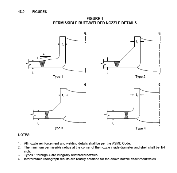
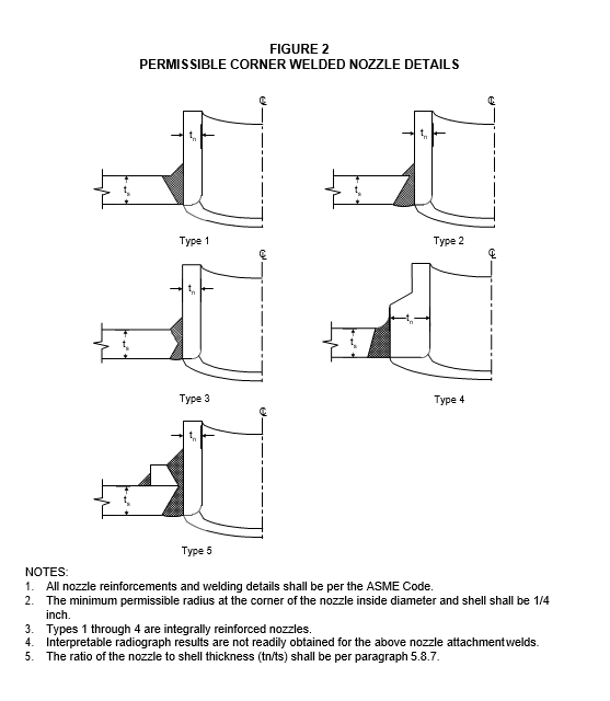
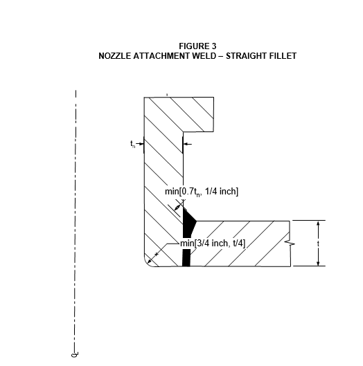
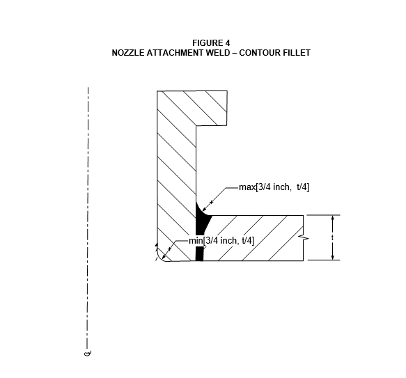
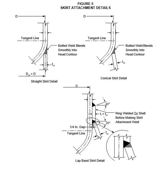
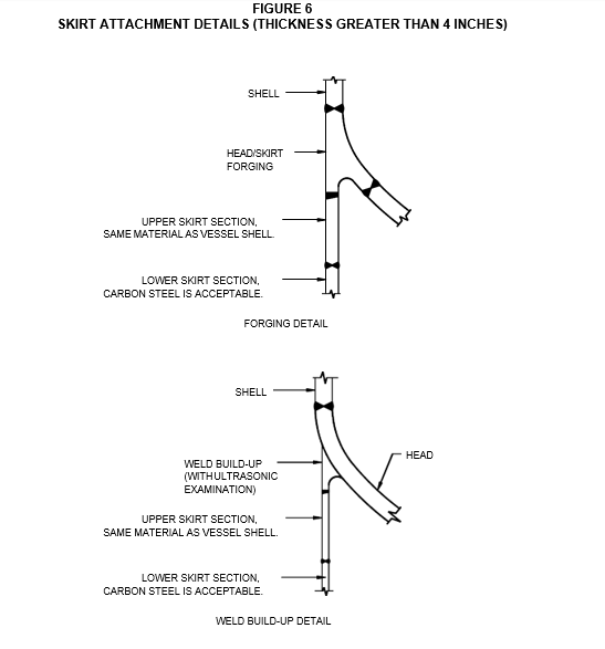
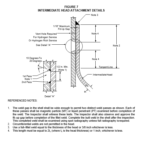
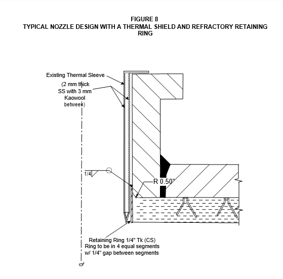
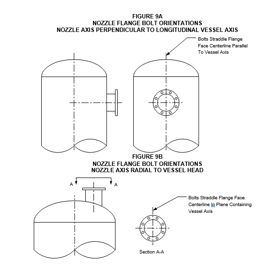
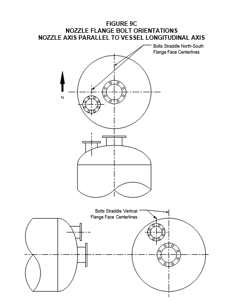
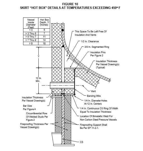
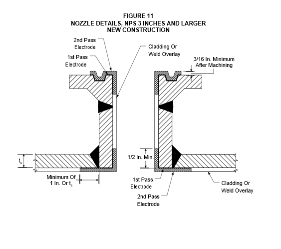
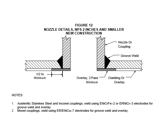
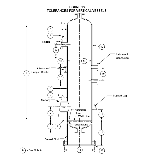

FIGURE 13
TOLERANCES FOR VERTICAL VESSELS (CONTINUED)
NOTES:
- Tolerance on longitudinal dimensions from the reference plane shall be the smaller of 1/64 in. per foot of length or 1/2 in., unless otherwise noted.
- Reference plane, mark inside and outside of the vessel with a low stress stamp.
- Flange face of nozzle from outside of vessel ±1/4 in.
- Flange face of nozzle shall be parallel with the indicated plane in any direction ±1/2 , but not to exceed 3/16 in
- Location of nozzle from reference plane ±1/4 in.; exception shall be liquid level controller nozzles
±1/16 in. nozzles related to tray, draw–off pans, etc., so dimensioned on drawings, distance from support ring ”1/8 in.
- Flange face of manway from outside of vessel ±1/4 in.
- Flange face of manway shall be parallel with the indicated plane in any direction ±1/2 degree.
- Location of manway from reference plane ±1/2 in.
- Flange face of top or bottom nozzle to reference plane ±1/4 in.
- Maximum deviation from straight applied to shell shall be: 1/8 in. in any 10 feet or 1/2 in. per 50 feet of length with a maximum total deviation of 1 inch. In addition, distortion caused by welding of longitudinal or circumferential joints shall not exceed 1/4 in. maximum depth in a 36 in. length of shell centered on the weld.
- Distance from reference plane to base +0 in, - 1/4 in. or lug +1/4 in, -0 in.
- Base or support lug out of level over any diameter shall be as given in Table F12.1.
- Bolt hole circle tolerance shall be as given in Table F12.1.
- Tolerance from nominal inside shell diameter as measured by external strapping shall be as given in Table F12.1.
- Instrument centerlines, 1/8 in.
- Distance between bolt holes, ±1/32 in.
- Distance from bottom bolt hole to reference plane, ±1/8 in.
- Orientation of nozzles and other attachments shall be within ±1/8 in.
- 1/8 in. maximum lateral translation.
- 1/16 in. maximum rotation of flanges from indicated position measured as shown.
TABLE F12.1
| Note Number | Tolerances (Inches) | Tolerances (Inches) | Tolerances (Inches) | Tolerances (Inches) |
|---|---|---|---|---|
| Note Number | Specified Inside Diameter | Specified Inside Diameter | Specified Inside Diameter | Specified Inside Diameter |
| <4 Ft. | 4 Ft. Up To 7 Ft. | 7 Ft. Up To 16 Ft. | >16 Ft. | |
| 12 | ±1/8 | ±3/16 | ±1/8 | ±1/4 |
| 13 | ±1/8 | ±1/8 | ±1/4 | ±1/4 |
| 14 | ±3/8 | ±1/2 | ±3/4 | ±1 |
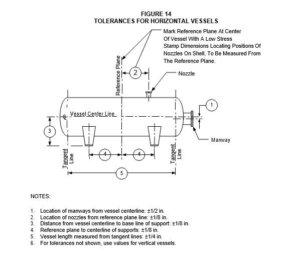
© 2026 Inflection Point Engineering, LLC. All rights reserved. The content of this page — including calculation methods, reference data, written analysis, interactive tools, and source code — is the intellectual property of Inflection Point Engineering, LLC and is protected under applicable copyright, trademark, and trade secret laws. Unauthorized reproduction, redistribution, modification, or derivative use in whole or in part is prohibited without prior written consent.
Disclaimer. This material is provided for informational and educational purposes only and does not constitute professional engineering advice. Calculations, reference data, and methodologies are based on published standards and accepted engineering practice but are not a substitute for engineering judgment, site-specific analysis, or review by a licensed Professional Engineer. Inflection Point Engineering, LLC makes no warranties, express or implied, regarding the accuracy, completeness, or fitness for a particular purpose of any content presented here, and shall not be liable for any direct, indirect, incidental, or consequential damages arising from its use. Users assume all risk associated with applying this content to real-world design, operations, or decisions.
© 2026 Inflection Point Engineering, LLC. All rights reserved.