 Section 7 — Pressure Vessels
Pressure Vessel Details
IPE Engineering Practice IPE-EP-7-1-7
Document number: IPE-EP-7-1-7 · Section: 7 — Pressure Vessels
SCOPE
- This Practice provides supplemental design details for standard pressure vessel supports, structural attachments, appurtenances, and lifting lugs. The basic requirements for the design, materials, fabrication, inspection and testing, and shipment of pressure vessels are covered in EP 7-1-1.
- Any deviation from this Practice must be approved by the procedure described in EP 1-1-3.
- An asterisk (*) indicates that a decision by the Owner or Owner's Engineer is required, or that additional information is furnished by the purchaser.
- A revision bar indicates all changes made to this Revision.
2.0 REFERENCES
The latest edition of the following standards and publications are referred to herein.
STANDARDS AND PUBLICATIONS
| IPE Engineering Practices |
|---|
| EP 1-1-3 Deviations to r Engineering Practices EP 7-1-1 Pressure Vessels EP 7-1-3 Heavy Wall and Special Service Pressure Vessels EP 7-1-5 Welding Requirements for Pressure Vessels EP 13-15-1 Equipment Grounding Details |
| ASME Codes |
| Sec II Material Specifications Sec VIIIPressure Vessels, Division 1 Sec VIIIPressure Vessels, Alternative Rules, Division 2 |
DEFINITIONS
- Aggressive Environmental Service (AES) - Process services which result in material degradation such as cracking, scaling, blistering, and severe pitting and/or corrosion. Examples of such services are hydrogen service, wet hydrogen sulfide, cyanides, caustic, amine, and hydrofluoric acid. AES process fluid are defined in EP 10-2-1.
- ASME Code - Refers to the ASME Boiler and Pressure Vessel Code, Section VIII, Division 1 or Division 2, as applicable.
- Contractor - Company or business that agrees to furnish materials or perform specified services at a specified price and/or rate to the Owner.
- Hydrogen Rich Service - A service defined as a combination of hydrogen partial pressure and temperature at or below the curve for carbon steel per Figure 1 of API Publication 941, latest edition, and with a hydrogen partial pressure greater than 100 psia.
- Hydrogen Service - A service defined as a combination of hydrogen partial pressure and temperature above the curve for carbon steel per Figure 1 of API Publication 941, latest edition.
- Inspector - A Inflection Point Engineering, LLC appointed engineer or inspector.
- Lethal Substances - As defined by the ASME code, Section VIII, Division 1: "By 'lethal substances' are meant poisonous gasses or liquids of such a nature that a very small amount of the gas or of the vapor of the liquid mixed or unmixed with air is dangerous to life when inhaled."
- Manufacturer - The recipient of a direct or indirect purchase order for materials and/or equipment. In this context, a direct order is one issued to a manufacturer by a contractor or the Owner. An indirect order is one issued to a manufacturer by a vendor (recipient of a direct order) for materials, fabricated components, or subassemblies.
- Owner - Inflection Point Engineering, LLC.
- Owner's Engineer - A Inflection Point Engineering, LLC appointed engineer.
- Purchase Order - The contractual document given to the Manufacturer to authorize a purchase.
- Purchaser - The party placing a direct purchase order. The purchaser is the Owner's designated representative.
MATERIALS
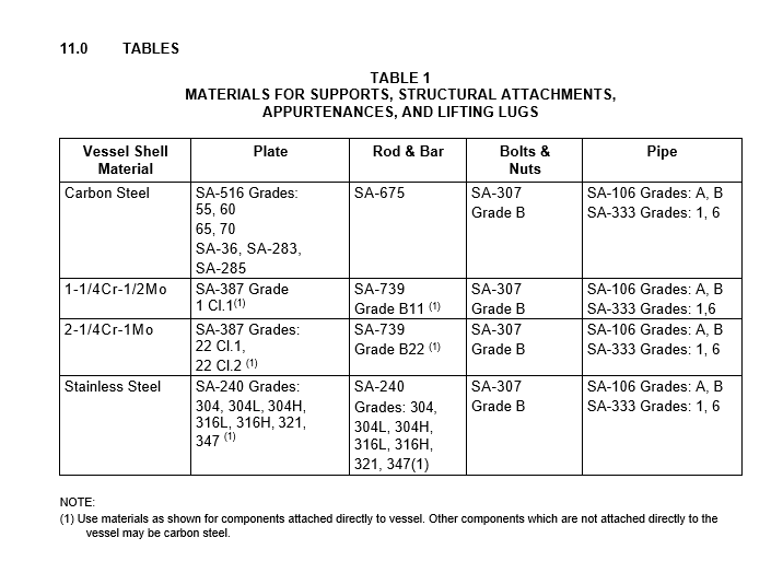
- (*)Unless otherwise specified by the Owner's Engineer, materials for construction of pressure vessel supports, structural attachments, appurtenances, and lifting lugs shall be in accordance with Table 1.
- Support skirt material requirements for vertical vessels constructed of materials other those shown in Table 1 are stipulated in EP 7-1-1.
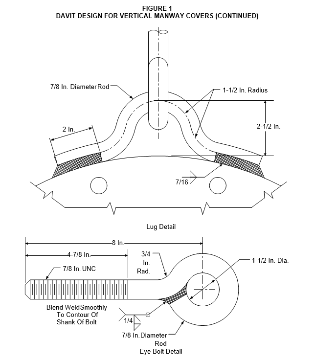
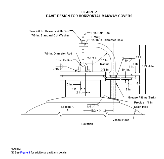
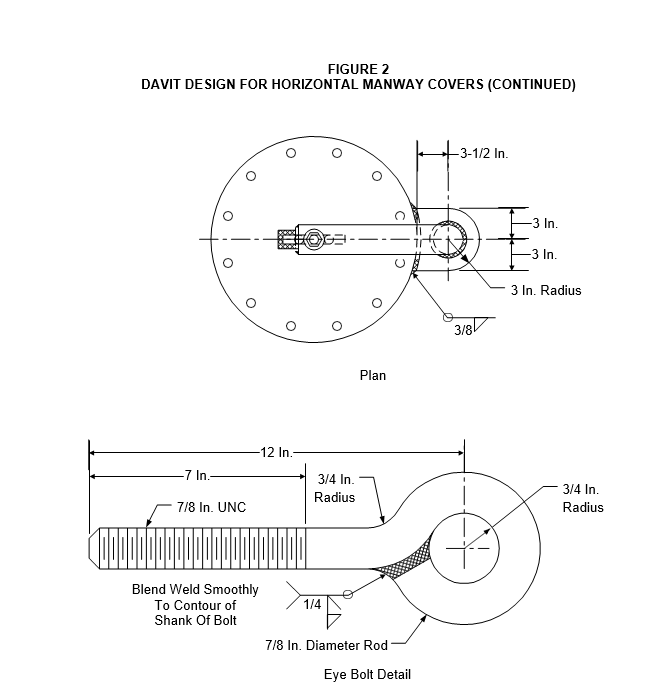
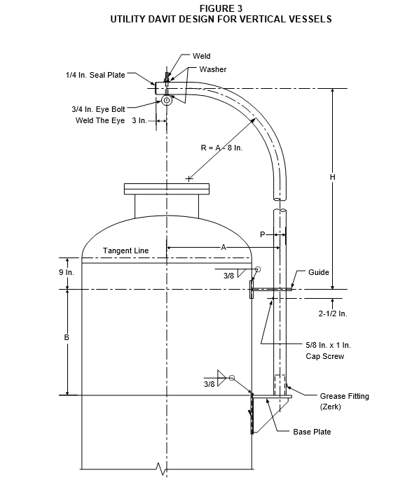
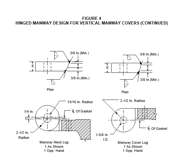
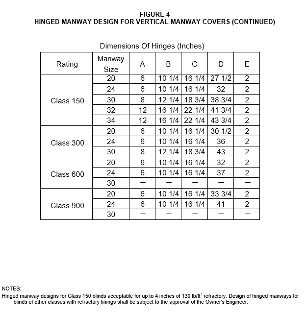
DAVITS AND HINGED MANWAYS
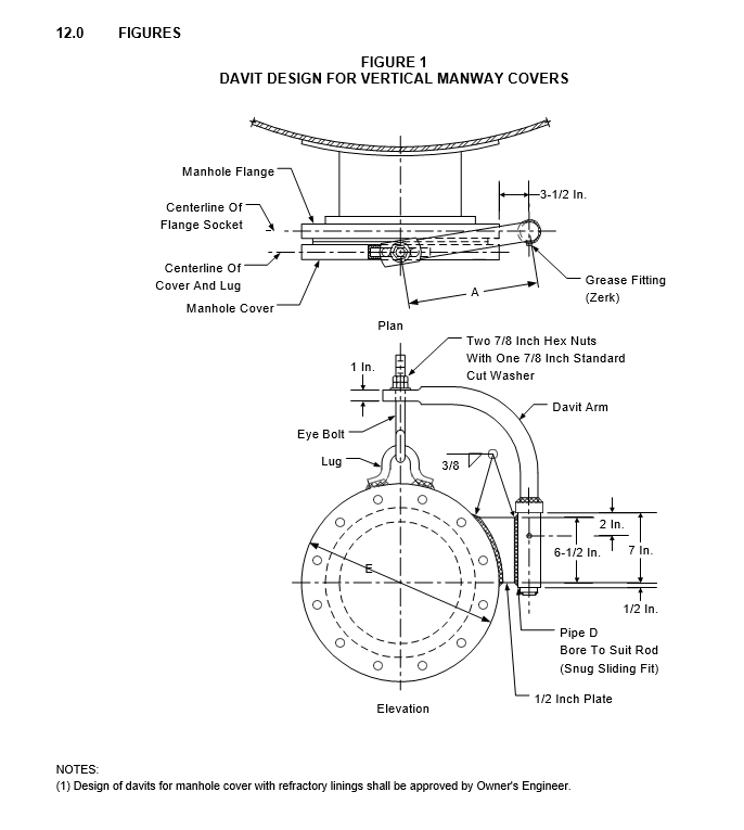
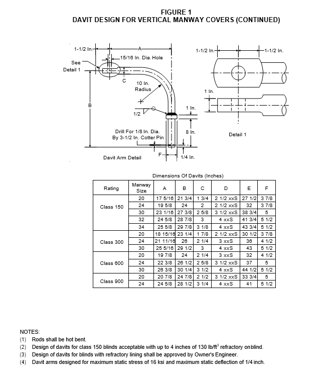
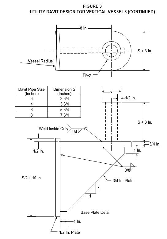
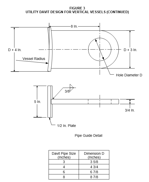
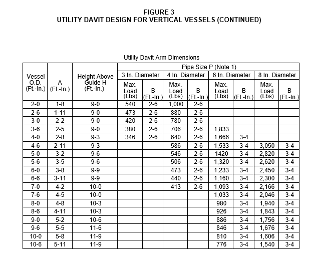
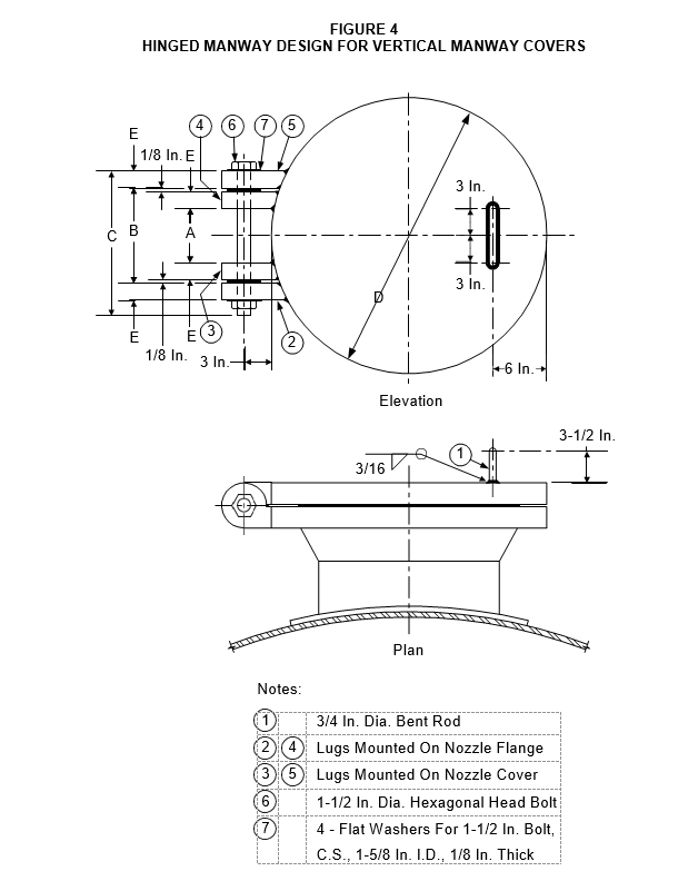
- (*)Davit and hinged manway designs shall be in accordance with details illustrated in Figure 1, Figure 2, Figure 3, and Figure 4. Alternative davit and hinged manway designs are subject to the approval of the Owner's Engineer.
- All davits shall be furnished with a stainless steel tag which lists the maximum lifting capacity of the davit. The capacity tag shall be located such that the marked lifting capacity is visible from the vessel access platform or location in which the davit would be operated. The letters and figures marked on the capacity tag shall be at least 5/32 inch high.
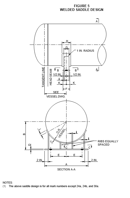
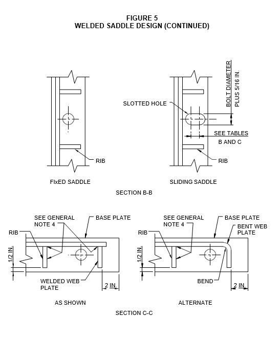
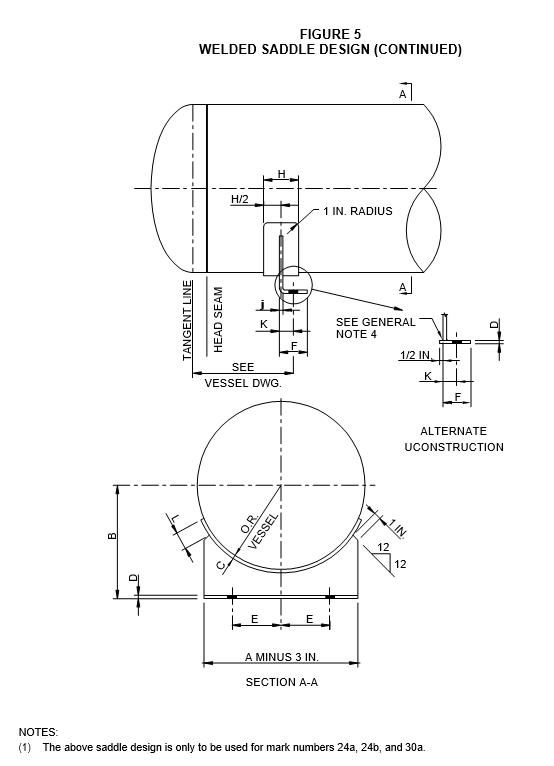
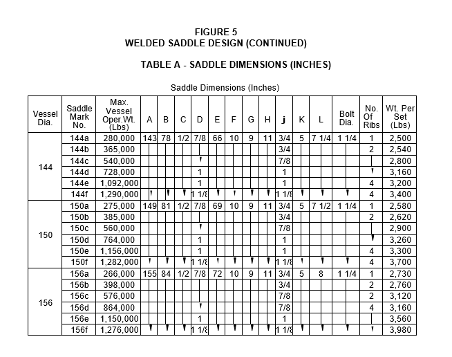
SADDLE SUPPORTS FOR HORIZONTAL VESSELS AND HEAT EXCHANGERS
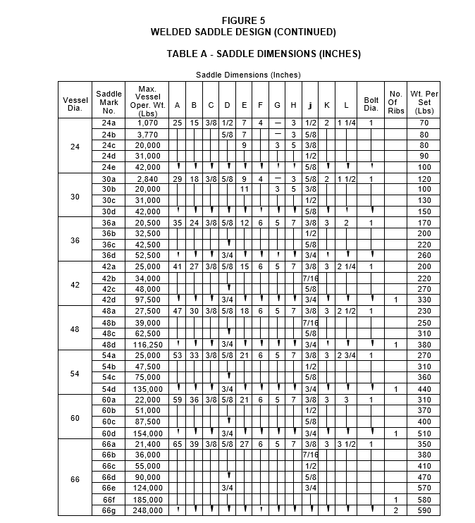
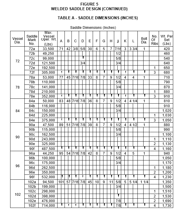
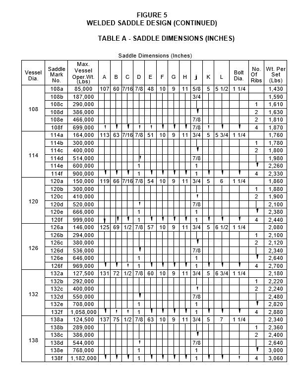
- Saddle supports shall be in accordance with details illustrated in Figure 5. In the case of vessel geometries not addressed in Table A of this figure, alternate saddle supports shall be designed and included on the vessel fabrication drawings.
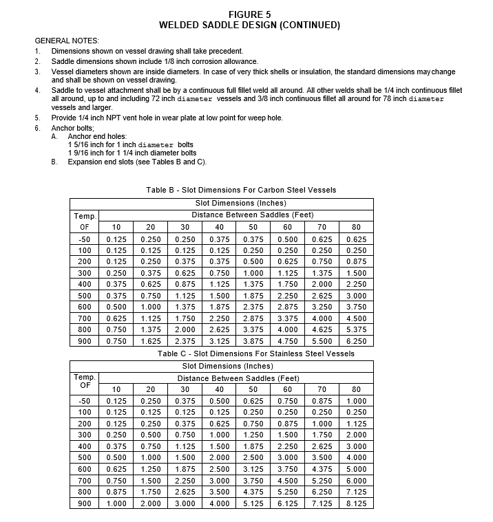
- Saddle supports shall have unslotted holes in the fixed end support and slots in the movable end support. The length of the slots shall be per Figure 5, Tables B and C based on the design temperature of the shell.
- (*)Slide plates shall be installed underneath the baseplate of the movable end support. The slide plate design shall be in accordance with EP 4-2-9 unless otherwise specified by the Owner's Engineer.
- Stiffening rings at the saddle supports, when required shall be located on the outside of the vessel.
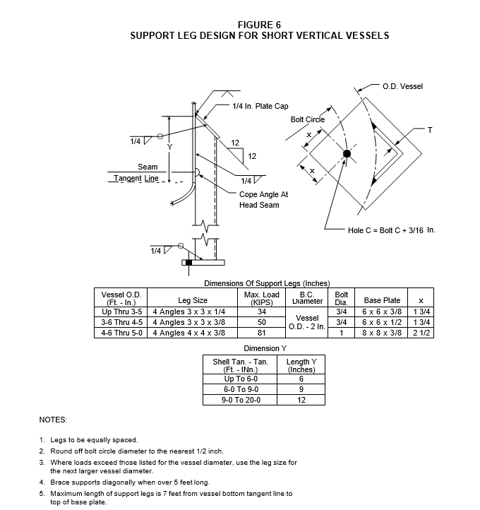
SKIRT AND LEG SUPPORTS FOR VERTICAL VESSELS
- (*)Leg supports shall be in accordance with Figure 6. Alternative designs for leg supports are subject to the approval of the Owner's Engineer. Details for lug type supports shall be as shown on the vessel drawing(s) and are subject to the approval of the Owner's Engineer.
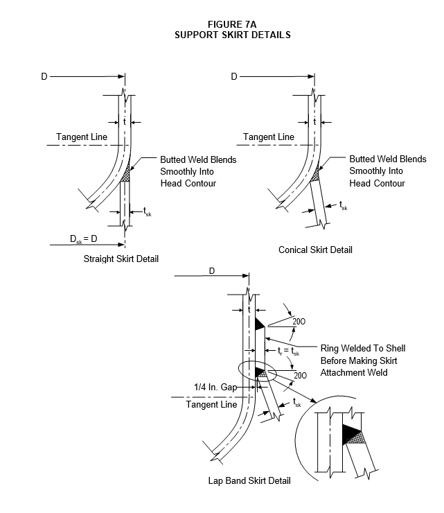
- (*)Skirt supports shall be in accordance with details illustrated in Figure 7A. Alternative designs for skirt supports are subject to the approval of the Owner's Engineer.
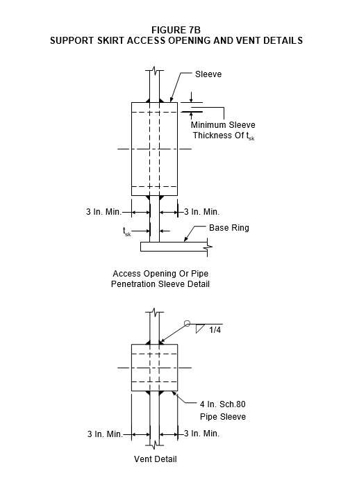
- Access and pipe penetration openings shall be in accordance with Figure 7B.
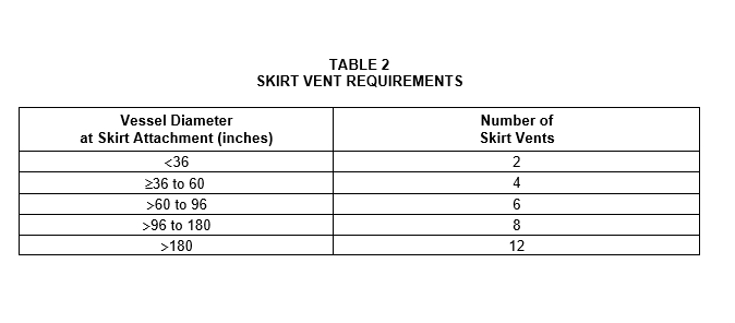
- Nipples shall be provided near the top of the skirt to vent the space at the bottom head intersection. The vent openings shall be in accordance with Figure 7B and shall be equally spaced around the circumference of the skirt and shall be clear of all insulation and fireproofing. The number of vents required is shown in Table 2.
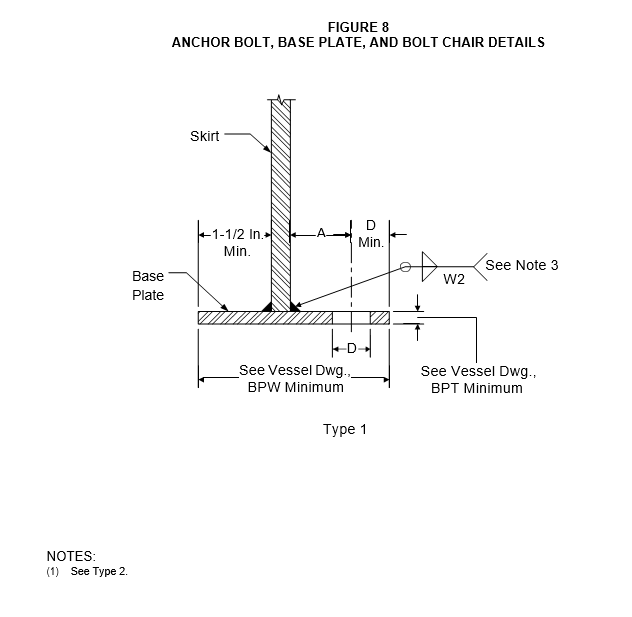
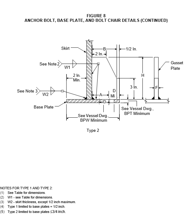
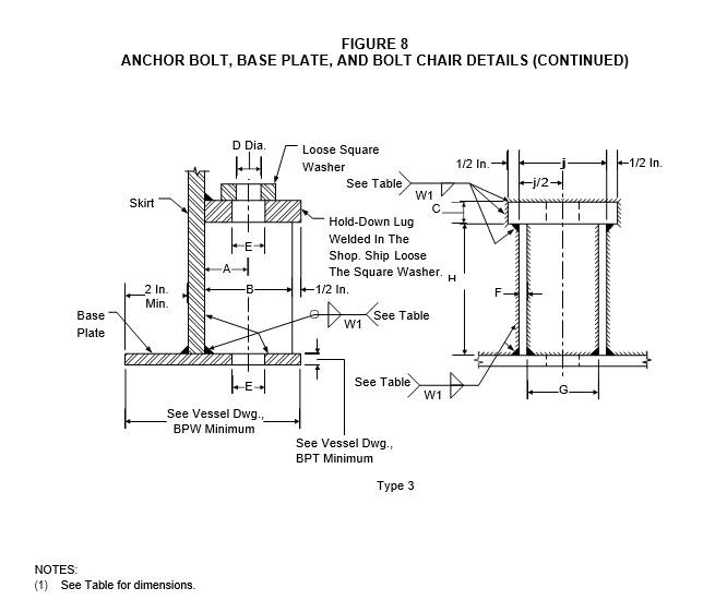
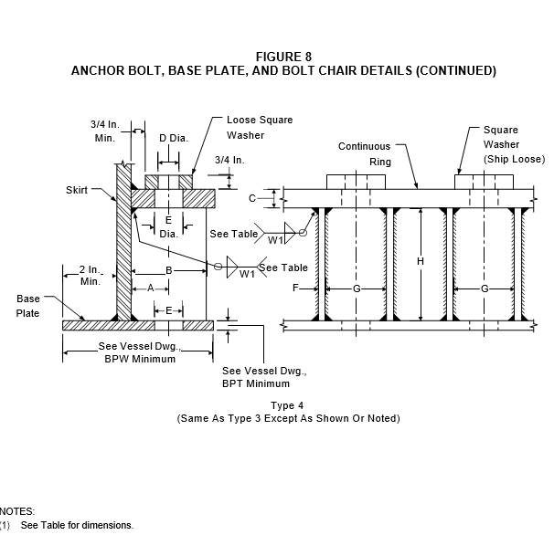
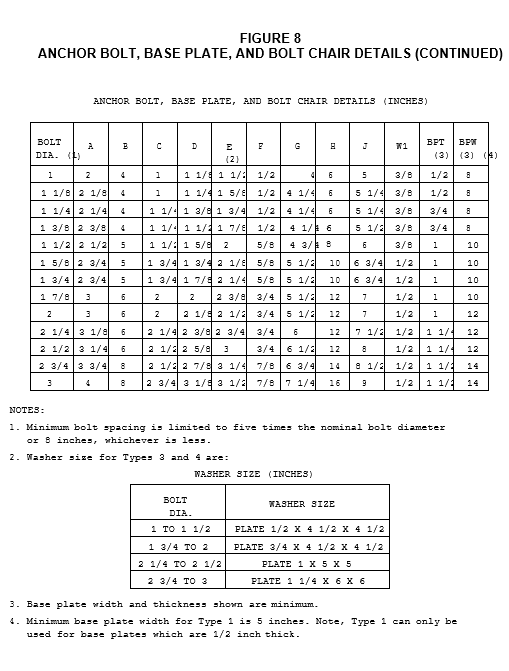
- Support skirt base plate and anchor bolt chair designs shall be one of the types (I, II, III, or IV) shown in Figure 8.
LIFTING LUGS
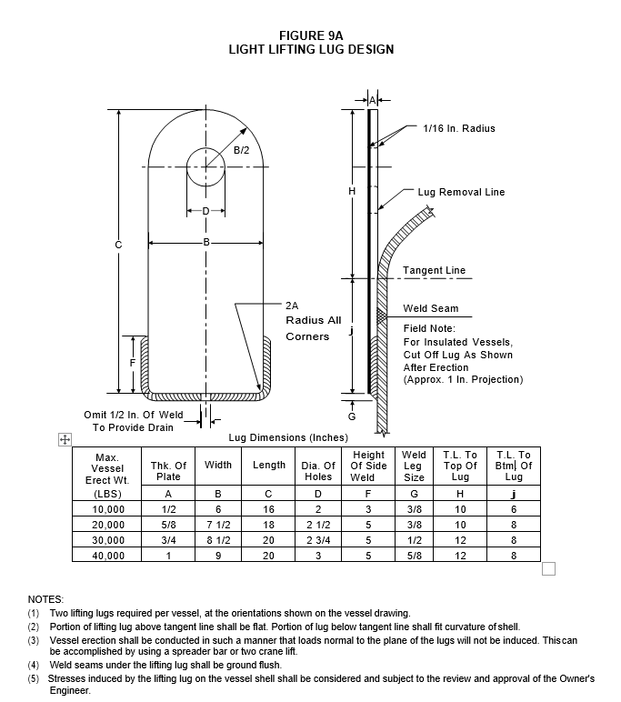
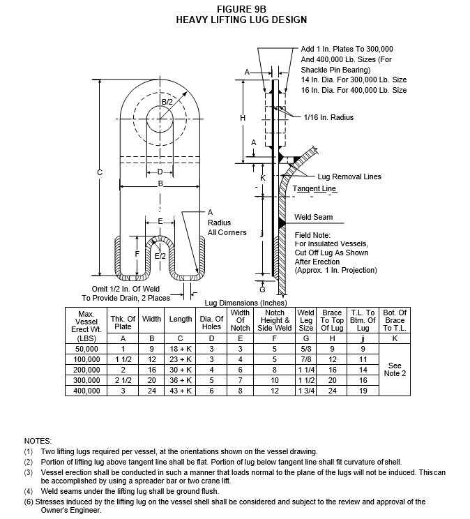
- (*)Lifting lugs shall be in accordance with the applicable designs given in Figure 9A and Figure 9B. Alternative designs are subject to the approval of the Owner's Engineer.
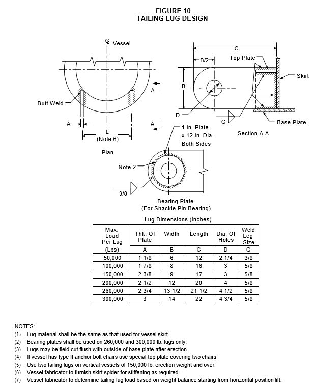
- (*)Tailing lugs shall be in accordance with Figure 10. Alternative tailing lug designs are subject to the approval of the Owner's Engineer.
9.0 GROUNDING DETAILS
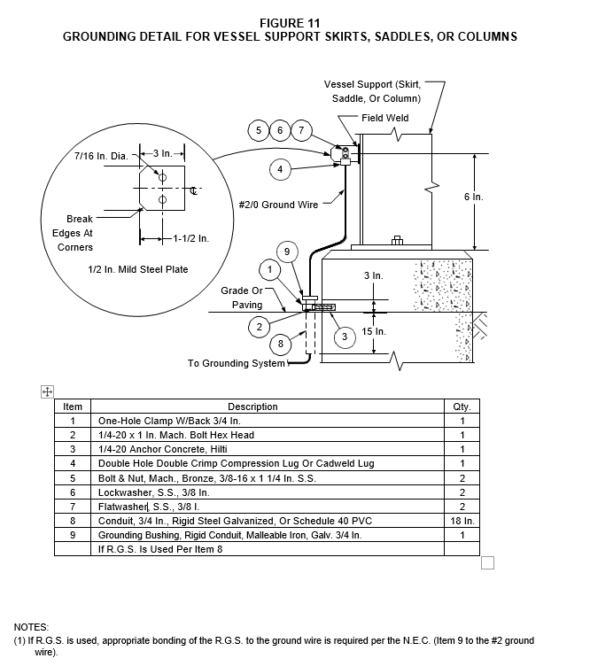
(*)Grounding details for vessels supported on saddles, columns, or skirts shall be in accordance with Figure 11 and EP 13-15-1. Alternative grounding details are subject to the approval of the Owner's Engineer.
10.0 DIMENSIONAL TOLERANCES
The tolerance on pressure vessel support, structural attachment, appurtenance, and lifting lug length and width dimensions given in the details in this Practice shall be -0, +1/4 inch, unless otherwise noted. All thickness dimensions given in this Practice shall be interpreted as minimum, unless otherwise noted.
© 2026 Inflection Point Engineering, LLC. All rights reserved. The content of this page — including calculation methods, reference data, written analysis, interactive tools, and source code — is the intellectual property of Inflection Point Engineering, LLC and is protected under applicable copyright, trademark, and trade secret laws. Unauthorized reproduction, redistribution, modification, or derivative use in whole or in part is prohibited without prior written consent.
Disclaimer. This material is provided for informational and educational purposes only and does not constitute professional engineering advice. Calculations, reference data, and methodologies are based on published standards and accepted engineering practice but are not a substitute for engineering judgment, site-specific analysis, or review by a licensed Professional Engineer. Inflection Point Engineering, LLC makes no warranties, express or implied, regarding the accuracy, completeness, or fitness for a particular purpose of any content presented here, and shall not be liable for any direct, indirect, incidental, or consequential damages arising from its use. Users assume all risk associated with applying this content to real-world design, operations, or decisions.
© 2026 Inflection Point Engineering, LLC. All rights reserved.