 Section 7 — Pressure Vessels
Metal Lining and Cladding
IPE Engineering Practice IPE-EP-7-1-6
Document number: IPE-EP-7-1-6 · Section: 7 — Pressure Vessels
SCOPE
- This Practice covers integral cladding, weld overlay, and alloy strip lining applications to carbon or low alloy steel base material. The alloy cladding, overlay, or strip lining shall be ferritic alloy steel, austenitic alloy steel, or nickel base alloy.
- Alloy strip lining shall be applied only as a repair method for existing "in-plant" equipment. New equipment shall not be strip lined.
- Any deviation to this Practice must be approved by the procedure described in EP 1-1-3.
- An asterisk (*) indicates that a decision by the Owner's Engineer or Owner is required, or that additional information is furnished by the Purchaser.
- A revision bar indicates all changes made to this Revision.
2.0 REFERENCES
The latest edition of the following standards and publications are referred to herein.
STANDARDS AND PUBLICATIONS
| IPE Engineering Practices |
|---|
| EP 1-1-3 Deviations to IPE Engineering Practices EP 7-1-1 Pressure Vessels EP 15-1-4 Positive Materials Identification (PMI) |
| ASME Code |
| Sec II Material Specifications Sec VIIIPressure Vessels, Division 1 and Division 2 Sec IX Welding Qualifications |
| API Publications |
| Publ 941 Steels for Hydrogen Service at Elevated Temperatures and Pressures in Petroleum Refineries and Petrochemical Plants. |
| AWS Standard |
| A4.2 Standard Procedures for Calibrating Magnetic Instruments to Measure the Delta Ferrite Content of Austenitic Stainless Steel Weld Metal. |
DEFINITIONS
- Alloy, Clad, or Weld Overlay Minimum Thickness - The minimum depth of weld overlay, cladding or lining that maintains the nominal composition of the specified alloy.
- Alloy Lining - The application of a thin corrosion resistant alloy sheet to the process side of a nozzle or pressure vessel constructed of a less noble alloy. The liner is attached to the base material by some combination of fillet welds, plug welds or spot welds.
- Contractor - Company or business that agrees to furnish materials or perform specified services at a specified price and/or rate to the Owner.
- Hydrogen Rich Service - A service defined as a combination of hydrogen partial pressure and temperature at or below the curve for carbon steel per Figure 1 of API Publication 941, latest edition, and with a hydrogen partial pressure greater than 100 psia.
- Hydrogen Service - A service defined as a combination of hydrogen partial pressure and temperature above the curve for carbon steel per Figure 1 of API Publication 941, latest edition.
- Inspector - A Inflection Point Engineering, LLC appointed engineer or inspector.
- Integral Cladding - The product of roll bonding or explosive bonding alloy steel to a carbon steel or low chrome alloy backing plate.
- Manufacturer - The recipient of a direct or indirect purchase order for materials and/or equipment. In this context, a direct order is one issued to a manufacturer by a contractor or the Owner. An indirect order is one issued to a manufacturer by a vendor (recipient of a direct order) for materials, fabricated components, or subassemblies.
- Owner - Inflection Point Engineering, LLC.
- Owner's Engineer - A Inflection Point Engineering, LLC appointed engineer.
- Purchaser - The party placing a direct purchase order. The purchaser is the Owner's designated representative.
- Weld Overlay - The application of a corrosion resistant alloy weld deposit directly onto the base material surface of a nozzle or steel plate used to fabricate a pressure vessel.
MATERIALS
- (*)Materials for cladding, weld overlay, or strip lining shall be specified by the Owner's Engineer and shall comply with Table 1. Any request for a change in the specified material in this table or for a material substitution not listed in this table shall include the proposed material's ASME Code Designation, material grade, service properties and any previous known history in the proposed service environment.
- (*)The minimum clad, overlay or strip lining thickness shall be as shown in Table 2 for all components except heat exchanger tubesheets. The minimum clad or overlay thickness for heat exchanger tubesheets shall be as shown in Table 6.
- Austenitic stainless steel materials that will be subjected to PWHT as part of the vessel's fabrication sequence shall be "L" grade, or stabilized with additions of Ti or Cb.
CLAD PLATE REQUIREMENTS
- Welding of the alloy layer, including weld repair of clad plates, shall follow the requirements of paragraph 6.0.
- Inspection of clad plates for purchase or during fabrication shall follow the requirements of paragraph 11.1.
- Inspection requirements for back cladding shall be per paragraph 11.2.
- Brass clad tubesheets for heat exchangers shall be furnace brazed at temperatures greater than 1000F.
WELD OVERLAY REQUIREMENTS
- Weld Overlay procedures shall be qualified in accordance with Section IX of the ASME Code, but shall use the same P-Number base material and type or brand of flux, weld wire, or electrode as that to be used in production welding. The postweld heat treatment temperature range used on the overlay qualification test plates shall be the same as that used in production. The postweld heat treatment time at temperature for the qualification test plates shall be the same or greater than that used in production.
- (*)All weld overlay or back cladding procedures and production welds shall have a minimum of two weld layers unless approved by the Owner's Engineer. The number of weld layers used in production welds shall not be less than the number used for procedure qualification.
- The weld overlay shall be applied in such a manner that the weld beads run circumferentially around the vessel. The surface contour shall be relatively smooth. Waviness is permissible but without notches and undercuts which might act as stress raisers. The beads may run longitudinally for nozzles with an inside diameter of 12 inches and smaller and for pipe elbows if followed by blend grinding.
- Alloy Limitations for Austenitic Stainless Steel are listed below:
- For any low-carbon (L, LC, or ELC) grades, the percent carbon shall not exceed 0.04 percent.
- For columbium (niobium) bearing grades (e.g., 347 and 309 Cb) the columbium to carbon ratio of the deposited metal shall not exceed 16:1.
- For weld overlay using the strip electrode technique, the maximum permissible strip width is 3.5 inches (90 mm).
- Vessels with Monel weld overlay designated for HF Acid service shall have the following requirements:
- Vessel overlay chemistry shall contain a maximum of 5% iron (Fe) in the top 1/16 inch of the final deposit.
- Overlays, deposited by manual processes, shall have a minimum of three layers.
- ERNi-1 filler metal is required for the first pass when welding with the GTAW or GMAW process.
- The maximum diameter of SMAW electrodes shall be 1/8 inch.
- Inspection requirements for weld overlay shall be per 11.2.
STRIP LINING REQUIREMENTS FOR VESSEL REPAIR
- Strip lining shall only be used for repair of existing pressure vessels. Strip lining shall not be used for the following services:
- (*)Non-vented liners in hydrogen or hydrogen rich service. Proposals to consider strip lining of existing equipment in hydrogen service will be considered only if the design employs venting. Such proposals shall be submitted for approval to the Owner's Engineer.
- Vessels subject to postweld heat treatment (PWHT) unless special procedures for design and installation can be used.
- Vessels with design temperature greater than 700F.
- Vessels with a design pressure greater than 250 psi.
- Vessels that operate at negative pressure or, that cycle between positive and negative pressure.
- Vessels that are designated as "Lethal Service" per the ASME Code.
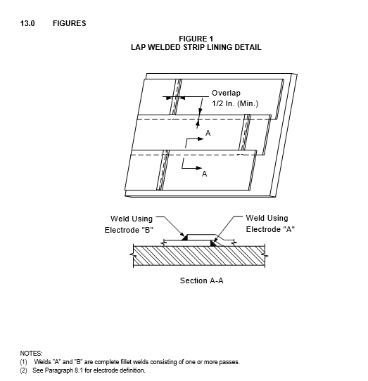
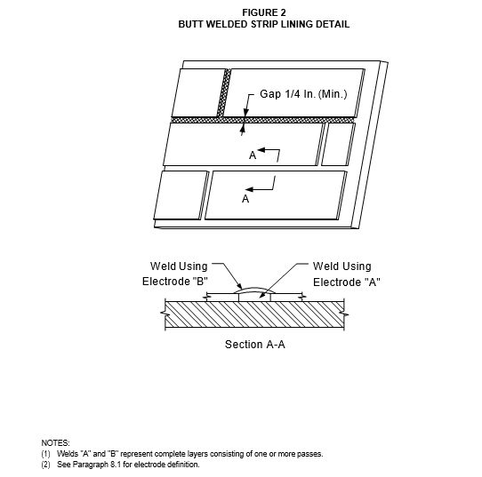
- Strip linings shall be lap welded per Figure 1 or butt welded per Figure 2. Fabrication drawings and the welding procedure specification shall describe the system to be used; and the welding procedure shall be qualified for the specific method and in accordance with the ASME Section IX Code.
- Dimensions of individual strips, excluding single piece sleeves, shall be limited by the following:
- (*)Thickness, unless specified and approved by the Owner's Engineer, shall not be less than 1/8 inch or more than 1/2 of the thickness of the shell to which it is attached.
- Widths shall be limited by design temperature and material, see Table 3.
- (*)Alternate proposals to use strips which are wider or thinner, or both, shall be submitted for approval by Owner's Engineer.
- Surfaces to be strip lined shall be cleaned to remove rust, mill, scale, dirt, weld spatter, and other foreign substances prior to the application of lining.
- Strip linings shall not terminate on top of a circumferential pressure boundary weld seam or be welded directly to any longitudinal seam.
- Inspection requirements for strip lining shall be per 11.3.
FILLER METAL REQUIREMENTS FOR STRIP LINING, CLADDING, AND WELD OVERLAY
- Filler metal (electrode) requirements for lap or butt-welded strip lining are shown in Table 4.
- Filler metal (electrode) requirements for clad and weld overlayed plate are shown in Table 5.
VESSEL SEAM AND NOZZLE CONNECTIONS
- Vessel Seam Details
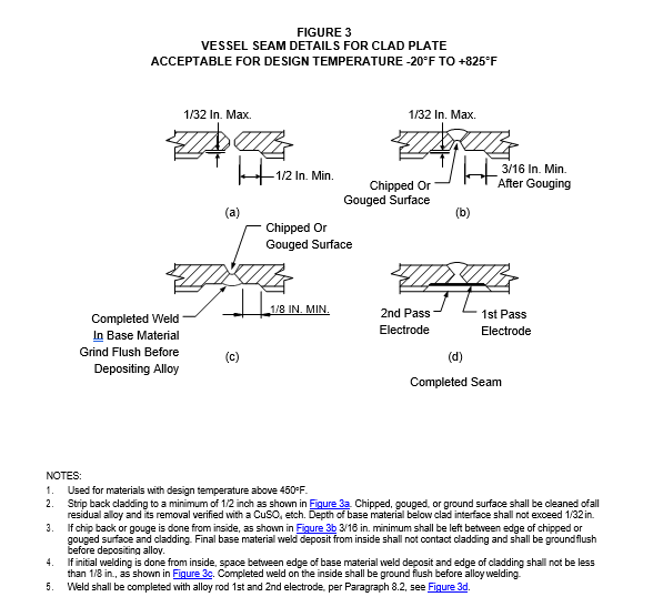
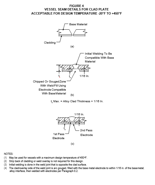
- Weld seam details for vessels with clad plate shall follow the requirements as shown in Figure 3 and Figure 4 .
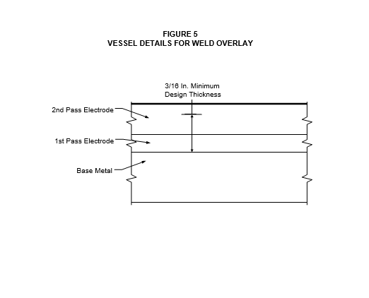
- Weld seam details for vessels with weld overlayed plate shall follow the requirements as shown in Figure 5.
- Nozzles and Manways
- Sleeve liners, overlay or clad material used for connections shall be the same material and thickness as used for the lining or cladding of the vessel or head to which they are attached.
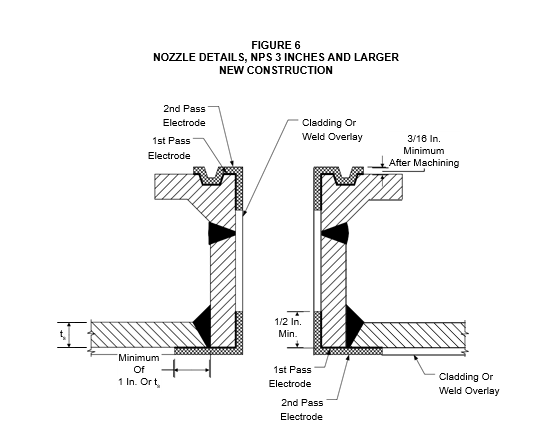
- Nozzles NPS 3 inches and larger shall be weld overlayed or of clad material, see Figure 6 . Nozzle necks (NPS 8 inches and larger) made from rolled plate may be fabricated from integrally clad plate if the size is large enough to produce satisfactory weld joints where the inside surface can be backchipped and welded after the carbon or low alloy steel weld is completed.
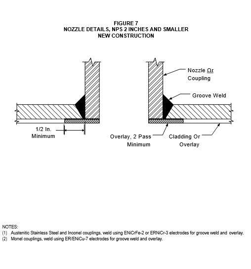
- Nozzles NPS 2 inches and smaller shall be either of the following:
- Weld overlay or integrally clad by the explosive bonding method, see Figure 6.
- Solid alloy, see Figure 7, provided the following conditions are met:
- Vessel design temperature is 450F maximum for stainless steel alloys and 800F maximum for Inconel or Incoloy alloys.
- When cladding is 11-13% chrome, couplings shall be Ni base alloy or austenitic stainless steel welded with ENiCrFe-2 electrodes. Couplings of 11 to 13% chrome shall not be used.
- When the vessel clad or overlay is Ni base or austenitic stainless steel, the coupling shall be of matching chemistry and welded with ENiCRFe-2 (Incro-A) electrodes.
- (*)Material selection, welding procedures, and installation details are approved by Owner's Engineer.
- All nozzles and manways shall be welded to the vessel by first stripping the clad from the weld area, verifying complete alloy removal with a CuSO4 etch, installing the fitting, then rewelding the alloy overlay using the electrodes listed in Table 5. Installation details are shown in Figure 6 or Figure 7.
- All connections shall be trimmed flush with the inside surface of the vessel and shall have a minimum 1/4 inch ground radius at inner corner of nozzle neck. In no case shall the required finished overlay be thinned by grinding.
- Flange faces of lined nozzles and manways that are weld overlayed with corrosion-resistant alloy shall be finish-machined over the gasket area, see Figure 6 . Machined overlay shall be 3/16 inch minimum thickness and comply with requirements for weld overlays outlined in this Practice.
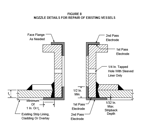
- Alloy liners or sleeves shall only be used for repair of existing vessels. Replacement of an existing liner or sleeve with a new one is an acceptable method of repair. However, if the complete nozzle is to be replaced, it shall be of clad or weld overlay construction. Repair of existing liners and sleeves shall satisfy the following requirements.
- (*)Sleeves or strip lining may be installed as a repair, but shall not be used, unless otherwise approved by the Owner's Engineer, if the vessel is subject to PWHT after installation, design temperature exceeds 700F, or design pressure exceeds 250 psi.
- Alloy sleeve liners shall be either seamless or rolled and welded with full fusion GTAW weld, before being inserted into a nozzle neck. The liner shall be rigidly attached to the vessel shell.
- Sleeve liners shall be welded to the connection at their extremities with welds of sufficient cross-section to develop the full strength of the sleeve liner and to withstand forces due to differential expansion. Weld overlay shall be used for the flange facing, see Figure 8.
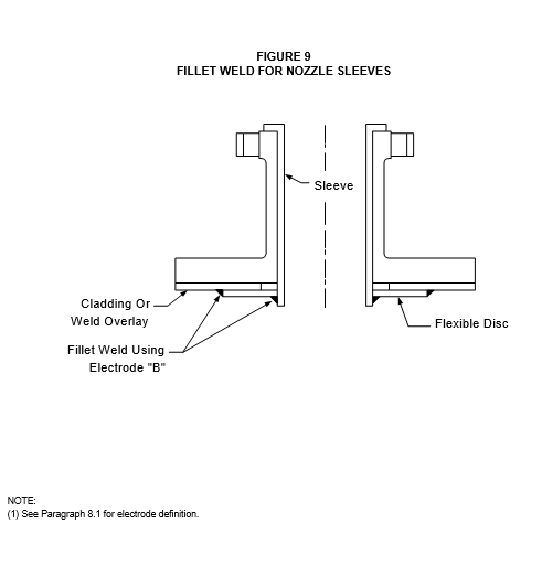
- (*)Sleeve designs using a flexible disc - similar to that illustrated in Figure 9 shall be submitted for review and approval by the Owner's Engineer.
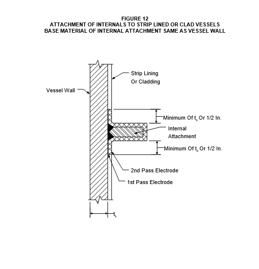
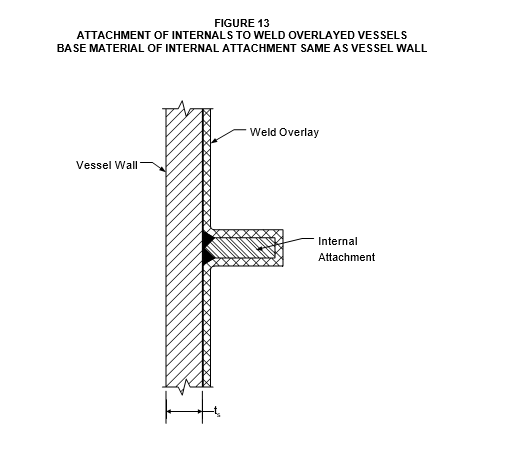
ATTACHMENT OF INTERNALS
- When the base material of the attachment is the same as the cladding material, the attachment shall be as given below.
- For clad or strip lined vessels, the internals shall be attached as follows:
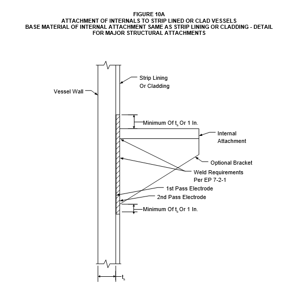
- (*)Major structural attachments - the internal attachment weld shall be made to a weld overlayed surface, see Figure 10A. When approved by the Owner's Engineer, major structural attachments may be made directly to the cladding if the integrity of the clad plate can be substantiated by test records and/or inspection. Major structural attachments include the following attachment types.
- Point supports (chair or lug) for beams and columns
- Tray support rings with a thickness greater than or equal to 1/2 inch
- Supports for internal piping with a thickness greater than 1/2 inch
- Any other attachment (regardless of thickness) where the computed bending stress exceeds 80% of the allowable stress of the internal evaluated at the vessel design temperature per the ASME Code, Section VIII, Division 1.
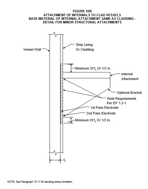
- Minor structural attachments - the internal component may be welded directly to the cladding, see Figure 10B. Minor structural attachments include all attachments that are not major structural attachments, see above.
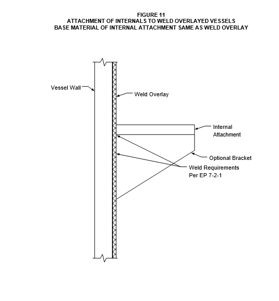
- For weld overlayed vessels, the internal attachment shall be welded directly to the weld overlay, see Figure 11.
- When the base material of the attachment is the same as the base material of the vessel shell, the attachment shall be welded directly to the shell using a full penetration weld. The attachment and the shell in the vicinity of the attachment shall then be weld overlayed with a material that is compatible with the strip, cladding or overlay lining of the vessel, see Figure 12 and Figure 13.
INSPECTION AND TESTING
- Integral Cladding
- Clad plate shall be purchased with shear test requirements or as otherwise specified by the Owner's Engineer. Shear strength tests of the clad interface shall be conducted for 11%-13% chrome (AISI Type 405, 410, 410S) steel, austenitic stainless steel, nickel alloy, and copper- nickel integrally clad base materials and shall meet the shear strength test requirements of the ASME Code, Section II, SA 263, SA 264, SA 265, and SB 432 respectively.
- Clad plate for vessels in Hydrogen service shall be ultrasonically tested to the following requirements unless otherwise specified by the Owner's Engineer. Inspection should be done at the Manufacturer's location before shipment to the fabricator.
- Subsequent to cladding and prior to fabrication, integrally clad material shall be subjected to an ultrasonic examination from the clad side per the ASME Code, Section II, SA 578, Supplement S-6. Scanning shall be in continuous parallel paths on 3 inch centers per paragraph 5.6 of SA-578. Indications of unbond per Supplement paragraph S6.4 shall be 1 inch rather than the 3 inch as currently specified in the paragraph.
- Material that is to receive a PWHT shall have all indications that show a 50% or greater loss of back reflection marked and recorded prior to heat treatment. Subsequent to PWHT, integrally clad material shall be re-examined ultrasonically in all locations of previously recorded discontinuities and other indications that resulted in 50 percent or greater loss of back reflection.
- For clad heads, final ultrasonic testing shall be performed after forming. All weld overlay seams in the heads shall be inspected for lack of bond at the weld to clad interface along the (100%) seam length.
- All weld seams that require radiographic inspection shall be tested before the alloy weld overlay backing is applied to the seam.
- For 11-13% chrome (405, 410S) clad vessels, each main seam shall be spot radiographed per the ASME Code, Section VIII paragraph UCL-36 after the weld overlay backing is complete.
- Cladding shall be removed where any rejectable lack of bond is detected and the area shall be repaired by weld overlay.
- Weld Overlay
- Weld overlay deposit shall be a minimum of 3/16" thick for overlay, 1/8" thick for back cladding, or 0.10 for clad plate repairs and shall be spot verified by ultrasonic examination. At least 2 spots per plate or head and one spot per weld seam shall be examined. Areas of clad or weld overlay that have been ground or machined below the surface of the surrounding area shall be measured to insure a minimum alloy depth in accordance with paragraph 4.2.
- (*)Weld Overlay Deposits shall be inspected to the following requirements unless otherwise specified by the Owner's Engineer.
- The ultrasonic examination technique shall be per SA 578. All ultrasonic testing shall use a transducer of approximately 1 inch diameter except for nozzles, which may use smaller diameters to accommodate the nozzle circumference.
- Inspection shall be done prior to the final postweld heat treatment, but after at least one intermediate or dehydrogenation (hydrogen out-gassing) heat treatment.
- For weld overlayed shell plates, ultrasonic testing shall be performed on each plate. The inspection shall consist of two 6 inch wide paths across the full length of the plate. The inspection paths shall be perpendicular to the direction of weld overlay travel and shall be within 1 foot of each end of the plate.
- For weld overlayed heads, each head shall be inspected by ultrasonic testing of two 6 inch wide strips tested at 90 degrees such that they intersect at the center of the head.
- For weld overlayed nozzles, inspection shall be from either the inside diameter or outside diameter. The inspection path shall be a 3 inch wide strip around the nozzle circumference.
- For back cladding of weld seams, inspection shall be 10% of the total weld seam area equally distributed among the total number of seams.
- All areas for major structural attachments shall be inspected for overlay disbonding before welding of the attachment in place. Major attachments are listed in paragraph 10.1.1.
- For all inspections, indications of disbond greater than 1 inch diameter in any direction shall be cause for rejection. If the test area is rejected, the entire plate, head, nozzle, or weld seam shall be inspected.
- PMI examination of weld consumables prior to welding shall be in accordance with EP 15-1-4. Chemical analysis of weld overlay deposits shall be taken at a minimum depth of 1/16 inch below the final surface of the weld. Results of the chemical analysis shall meet the deposit analysis of undiluted weld metal. For production welds of overlay and back cladding, chemical analysis shall be taken at approximately 8 foot intervals along the shell and from each head.
- Liquid penetrant examination shall be done on 10% of the first layer of weld deposit overlay or back cladding. Inspection shall include as many "T" joints as possible.
- Completed weld overlay, back-cladding, and attachment welds to overlay or cladding, shall be 100 percent liquid penetrant examined. Examination and acceptance criteria shall be per EP 7- 1-1.
- The ferrite number for austenitic stainless steel weld overlay procedures and production welds shall be between 3 and 12FN as determined by the WRC 1988 diagram for ferrite prediction in stainless steels. Ferrite content for production welds shall be checked by a Ferritescope or chemical analysis. The Ferritescope shall be calibrated using the AWS Standard A4.2. If the production weld is subject to Post Weld Heat Treatment, the ferrite reading shall be measured before PWHT. The extent of the testing shall be one test per:
- Every 10 square feet of continuous overlay
- Each nozzle or manway installation
- Each area of overlay or clad stripback
- Each new spool of continuous overlay strip or wire electrode
- Strip Lined Vessels
- Any vessels requiring hydrostatic testing and any joint requiring radiographic examination shall be so tested before the lining is applied.
- The final pass of all strip lining attachment butt welds and all exposed fillet welds shall be examined by the Liquid Penetrant Method. Examination and acceptance criteria shall be per EP 7-1-1. Alternate methods of examination may be used with approval of the Owner's Engineer.
12.0 TABLES
TABLE 1
MATERIALS FOR METAL LININGS WELD OVERLAY OR CLADDING
| Corrosion Resistant Alloy | Composition | Spec. Clad/Liner |
|---|---|---|
| Ferritic Stainless Steel | 405 (1) 410S (0.08C max) |
SA263/SA240 SA263/SA240 |
| Austenitic Stainless Steel | 304, 304L (0.035 C max) 316, 316L (0.035 C max) 317L, 321 347 |
SA264/SA240 SA264/SA240 SA264/SA240 SA264/SA240 |
| Monel | 400 (Annealed) | SA265/SB127 |
| Inconel | 600 (Annealed) 625 (Annealed) |
SA265/SB168 SA265/SB168 |
NOTE:
Do not use for new fabrication.
TABLE 2
MINIMUM LINING THICKNESS
| Lining Type | Minimum Thickness (inches) |
|---|---|
| (*)Strip Lining | 1/16 with Owner's Engineer approval, otherwise 1/8 |
| Clad Lining | 0.10 |
| Weld Overlay | 3/16 |
TABLE 3
MAXIMUM STRIP LINING WIDTHS
| Design Temperature F |
Materials | Maximum Width (inches) |
|---|---|---|
| 600 | All | 6 |
| 600 | Stainless Steel | 4 |
| 600 | 410S, Inconel | 6 |
TABLE 4
FILLER METAL REQUIREMENTS FOR LAP OR BUTT WELDED STRIP LININGS
| Strip Lining Material | Strip Lining Material | Filler Metal Material | Filler Metal Material | Electrode "A" (1) (2) (5) | Electrode "B" (1) (2) (5) |
|---|---|---|---|---|---|
| AISI Type 405, 410S (4) |
AISI Type 405, 410S (4) |
Stainless Steel | Stainless Steel | E/ER 309L or E/ER 309 |
E/ER 309L or E/ER 309 |
| Inconel (Inco 82) |
Inconel (Inco 82) |
ERNiCR-3 | ERNiCR-3 | ||
| Inconel (Inco A, Inco 82) |
Inconel (Inco A, Inco 82) |
ERNiCRFe-2 or ERNiCRFe-3 | ENiCRFe-2 or ERNiCRFe-3 | ||
| AISI Type | 304 304L |
AISI Type | 308 308L |
E/ER309 or E/ER309L | E/ER308 (3) E/ER308L |
| AISI Type | 316 316L 317L |
AISI Type | 316 316L 317L |
E/ER309 or E/ER309L | E/ER316 (3) E/ER316L E/ER317L |
| AISI Type | 321 or 347 |
AISI Type 347 | AISI Type 347 | E/ER309 or E/ER309L | E/ER347 |
| Monel | Monel | Monel 400 | Monel 400 | E/ERNiCu-7 or E/ERNi-1 | E/ERNiCu-7 |
| Inconel | Inconel | Inconel 600 | Inconel 600 | ERNiCR-3 or E NiCRFe-2 | ERNiCR-3 or ENiCRFe-3 |
| Inconel 625 | Inconel 625 | ERNiCR-3 or E/ERNiCRMo-3 or ENiCRFe-2 |
ERNiCRMo-3 or ENiCRMo-3 |
NOTES:
- See Figure 1 or Figure 2 for electrode definition for welding of strip lining. See Figure 9 for electrode definition for welding internal sleeves.
- EXXXX is for the SMAW Process; ERXXXX is for the GTAW. GMAW, PAW or SAW Processes.
- Filler metal alloy should match liner alloy type.
- Do not use AISI Type 405 for new construction.
- Use of filler metals other than those listed shall require approval of the Owner's Engineer.
TABLE 5
FILLER METAL REQUIREMENTS FOR CLAD AND WELD OVERLAYED PLATE
| Cladding or Weld Overlay Material | Cladding or Weld Overlay Material | Filler Metal Material | Filler Metal Material | 1st Pass Electrode (1) (2) (5) | 2nd Pass Electrode (1) (2) (5) |
|---|---|---|---|---|---|
| AISI Type 405, 410S (3) (Clad Material Only) |
AISI Type 405, 410S (3) (Clad Material Only) |
Stainless Steel (4) | Stainless Steel (4) | E/ER 309L E/ER 309 | E/ER 309L E/ER 309 |
| Inconel (4) (Inco 82) |
Inconel (4) (Inco 82) |
ERNiCR-3 | ERNiCR-3 | ||
| Inconel (4) (Inco A, Inco 82) |
Inconel (4) (Inco A, Inco 82) |
ERNiCRFe-2 ERNiCRFe-3 | ENiCRFe-2 ERNiCRFe-3 | ||
| AISI Type | 304 304L |
AISI Type | 308 308L |
E/ER309 or E/ER309L | E/ER308 E/ER308L |
| AISI Type | 316 316L 317L |
AISI Type | 316 316L 317L |
E/ER309 or E/ER309L | E/ER316 E/ER316L E/ER317L |
| AISI Type | 321 or 347 |
AISI Type 347 | AISI Type 347 | E/ER309 or E/ER309L | E/ER347 |
| Monel | Monel | Monel 400 | Monel 400 | E/ERNiCu-7 or E/ERNi-1 | E/ERNiCu-7 |
| Inconel | Inconel | Inconel 600 | Inconel 600 | ERNiCR-3 or E NiCRFe-2 | ERNiCR-3 or ENiCRFe-3 |
| Inconel 625 | Inconel 625 | ERNiCR-3 or E/ERNiCRMo-3 or ENiCRFe-2 |
E/ERNiCRMo-3 |
NOTES:
- See Figure 3, Figure 4, Figure 5, Figure 6, Figure 8, Figure 10 and Figure 11 for weld location.
- EXXXX is for the SMAW Process; ERXXXX is for the GTAW, GMAW, PAW or SAW Processes.
- Do not use AISI Type 405 for new construction.
- Filler metal may be stainless steel for the first and second pass, or Inconel for the first and second pass.
- (*)Use of filler metals other than those listed shall require approval of the Owner's Engineer.
TABLE 6
MINIMUM CLAD OVERLAY THICKNESS FOR HEAT EXCHANGER TUBESHEETS
| Tubesheet Face | Minimum Thickness (inches) |
|---|---|
| Tubeside | 5/16 when tubes are expanded only(1) (2) (4) 3/16 when tubes are welded to tubesheet |
| Shellside | 3/8(3) (4) |
- For tubes that are to be expanded only, one roll expansion groove shall be machined in the 5/16 inch alloy layer and the second groove in the backing plate. The tubes shall be expanded into both grooves.
- Areas of the tubesheet, other than the tube expansion areas, shall have a minimum clad or overlay thickness of 3/16 inch.
- Shellside clad or overlay is not required unless specified on the exchanger data sheet.
- Clad or overlay in excess of 3/16 inch is required to properly seal the tube roll joint from corrosion when seal welding is not performed.
© 2026 Inflection Point Engineering, LLC. All rights reserved. The content of this page — including calculation methods, reference data, written analysis, interactive tools, and source code — is the intellectual property of Inflection Point Engineering, LLC and is protected under applicable copyright, trademark, and trade secret laws. Unauthorized reproduction, redistribution, modification, or derivative use in whole or in part is prohibited without prior written consent.
Disclaimer. This material is provided for informational and educational purposes only and does not constitute professional engineering advice. Calculations, reference data, and methodologies are based on published standards and accepted engineering practice but are not a substitute for engineering judgment, site-specific analysis, or review by a licensed Professional Engineer. Inflection Point Engineering, LLC makes no warranties, express or implied, regarding the accuracy, completeness, or fitness for a particular purpose of any content presented here, and shall not be liable for any direct, indirect, incidental, or consequential damages arising from its use. Users assume all risk associated with applying this content to real-world design, operations, or decisions.
© 2026 Inflection Point Engineering, LLC. All rights reserved.