 Section 7 — Pressure Vessels
Heavy Wall and Special Service Pressure Vessels
IPE Engineering Practice IPE-EP-7-1-3
Document number: IPE-EP-7-1-3 · Section: 7 — Pressure Vessels

SCOPE
- This Practice covers supplemental requirements governing the design, fabrication, inspection and heat treatment of materials of unfired pressure vessels and heat exchangers having a calculated thickness in excess of two (2) inches excluding the weld overlay and cladding, or other vessels designated by the Owner as special service. The basic requirements for the design, materials, fabrication, inspection and testing, and shipment of pressure vessels are covered in EP ?-1-1.
- Any deviation from this practice must be approved by the procedure described in EP 1-1-3.
- An asterisk (*) indicates that a decision by the Owner's Engineer or Owner is required, or that additional information is to be furnished by the Purchaser.
- A Revision Bar indicates all changes made to this Revision.
2.0 REFERENCES
The latest edition of the following standards and publications are referred to herein.
STANDARDS AND PUBLICATIONS
| Engineering Practices |
|---|
| EP 1-1-3 Deviations to Engineering Practices EP ?-1-1 Pressure Vessels EP ?-1-5 Welding Requirements for Pressure Vessels EP ?-2-1 Pressure Vessel Internals |
| ASME Codes |
| Sec V Non-Destructive Examination Sec VIIIPressure Vessels, Division 1 Sec VIIIPressure Vessels, Alternative Rules, Division 2 |
| ASTM Standards |
| E142 Standard Method for Controlling Quality of Radiographic Testing E?09 Standard Practice for Magnetic Practice Testing |
DEFINITIONS
- Certified Material Test Report (CMTR) - A document, or documents, on which are recorded the results of tests, examinations, repairs, or treatments required by the Material Specification. Supplementary or special requirements, in addition to the requirements of the Material Specification, as required by the Purchase Order shall also be included on the CMTR. The specification of the material being represented including the year of issue and the material heat number shall also be included on the CMTR. All such documents shall identify the applicable Material Specification and shall be identified to the material represented.
- Contractor - Company or business that agrees to furnish materials or perform specified services at a specified price and/or rate to the Owner.
- Inspector - A Engineering Company appointed engineer or inspector.
- Manufacturer - The recipient of a direct or indirect purchase order for materials and/or equipment. In this context, a direct order is one issued to a manufacturer by a contractor or the Owner. An indirect order is one issued to a manufacturer by a vendor (recipient of a direct order) for materials, fabricated components, or subassemblies.
- Owner - Engineering Company.
- Owner's Engineer - A Engineering Company appointed engineer.
- Purchaser - The party placing a direct purchase order. The purchaser is the Owner's designated representative.
DOCUMENTATION
- (*)When a design according to the ASME Code, Section VIII, Division 2 is specified, the Contractor shall submit the Design Specification to the Owner's Engineer for approval no later than its issuance for vendor's quotes. The Manufacturer's Design Report shall be submitted for review as the various sections are completed. The completed and certified Design Report shall be submitted for approval to the Owner's Engineer prior to the start of fabrication.
- (*)The certified Material Test Reports for low-alloy or impact-tested pressure components shall be submitted to the Owner's Engineer as soon as they are available.
DESIGN
- Analysis
- (*)All analysis procedures used to qualify the design of components and details not covered by the ASME Code are subject to the approval of the Owner's Engineer.
- When steady-state thermal gradients exceed 150F in a distance equal to where R and t
are the radius and thickness of the vessel component in question, a thermal stress analysis shall be performed. Additionally, a thermal stress analysis is required for all specified thermal transient load cases. The procedures of the ASME Code, Section VIII, Division 2 may be used for this analysis.
- Shells, Heads and Transitions
- Formed heads shall be hemispherical or 2:1 elliptical. Straight flange length shall be a minimum of 2 inches, not including the weld bevel preparation.
- Knuckles for conical transition sections shall have an inside radius no less that 16.5% of the outside diameter of the adjoining cylindrical section.
- Nozzles and Nozzle Flanges
- Nozzle reinforcement shall be integral; reinforcing pads shall not be used.
- Nozzle designs for pressure vessels shall be as follows.
- Nozzles with inside diameters 4 inches and less shall be per Figure 1 or Figure 2 of EP ?- 1-1.
- Nozzle with inside diameters greater than 4 inches shall be per Figure 2 of EP ?-1-1.
- In cyclic service, or when a fatigue evaluation is required per ASME Code, Section VIII, Division 2, all nozzle connections shall be in accordance with Figure 2 of EP ?-1-1.
- All thermowell connections shall be flanged and shall be NPS 2 inch minimum.
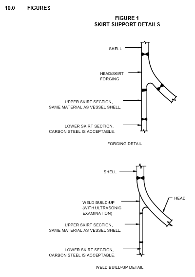
- Vessel Supports and Structural Attachments
- All vertical vessels shall be supported on a skirt. In low-alloy or tempered steel vessels, skirts that exceed 3/4 inch in thickness at their point of attachment shall be in accordance with Figure 1.
- Welds attaching nonpressure parts to pressure parts shall be the full-penetration type or continuous double fillet welds. Fillet welds shall be limited to the following:
- Lightly loaded attachments such as clips for insulation, ladders, and davits.
- A maximum size of 3/8 inch.
- A minimum distance of from gross structural discontinuities, including weld seams,
where R and t are shell radius and thickness, respectively.
MATERIALS
- General
- For all pressure containing materials and vessel internals, the Manufacturer shall supply a full specification including:
- Chemical Analysis.
- Guaranteed minimum mechanical properties after the maximum time at PWHT temperature.
- Heat treatment, if required, to achieve these properties.
- (*)Material selection shall be in accordance with EP ?-1-1; however, consideration may be given to use alternate materials covered by the ASME Code or ASME Code Cases. Final material selection will be specified by the Owner's Engineer.
- Material Inspection and Testing
- Plates shall be subject to ultrasonic examination in accordance with the ASME Code, Section VIII, Division 2, Paragraph Am-203. For plates with a thickness greater than 4 inches, ultrasonic examination shall be in accordance with SA-435, supplementary requirement S1.
- Forgings shall be examined ultrasonically to meet the requirements of Paragraph AM-203.2 of the ASME Code, Section VIII Division 2. Insofar as possible, the forgings shall be inspected so that 100% of the material is scanned from two perpendicular directions.
- All accessible surfaces of the forgings, including machined faces, shall receive a magnetic particle examination in accordance with Article 9-1 of the ASME Code, Section VIII, Division 2 and ASTM E ?09.
- Repairs in vessel plates or forgings shall be in accordance with EP ?-1-1 and the following:
- (*)Repairs to surface, sub-surface, and internal defects up to a depth of 1 inch from the surface may be permitted subject to Owner's Engineer's approval. Gouging and welding shall be in accordance with an approved procedure and preheat shall be uniform through the full section thickness for a distance of not less than 2t longitudinal and circumferential distance from the repair (t is the wall thickness of the item).
- Repairs to internal defects at a depth greater than 1 inch are not permitted.
FABRICATION
- Welding
- Attachment welds on the vessel, including those for platform clips, shall be continuous.
- The welded joint between the shell and skirt shall merge smoothly with the shell.
- Production weld test plates are required for all vessels. Weld test requirements are listed in EP
?-1-5.
- Heat Treating
(*)The requirements for time and temperature of intermediate or dehydrogenation post weld heat treatment during fabrication shall be reviewed and approved by the Owner's Engineer prior to the start of vessel fabrication.
INSPECTION AND TESTING
- Radiographic Examination
- All shell and head seams shall be subject to full radiography per EP ?-1-1.
- All welded butt joints joining integrally reinforced nozzles to the shell or heads (see Figure 2 of EP ?-1-1) shall be subject to full radiography per EP ?-1-1.
- The skirt to vessel weld shall be subject to full radiography per EP ?-1-1. Butt welds in the skirt shall be spot radiographed and must include all weld intersections.
- For radiographic inspection, fine grain, high definition, high contrast film (Kodak Type AA, or equivalent brands) shall be used. Film density of the weld area shall be within the range of 2.0 to 3.5 (3.? for skirt only) as determined by film density specimens or by densitometer. The radiographic quality level shall be 2-2T as defined in ASTM Specification E 142.
- Wherever practicable, radiographs shall be made with 15 MEV Betatron or equipment that will develop the density and quality required in paragraph 8.1.4 of this Practice. Radiography using Cobalt 60 isotopes is limited to seven inch thick weldments.
- Radiographic examination for final acceptance shall be performed after final post weld heat treatment.
- Ultrasonic Examination
- All butt welded joints in the shell and heads shall be 100% ultrasonically examined after hydrotest.
- All nozzle-to-shell or nozzle-to-head welds shall be 100% ultrasonically examined after hydrotest.
- All weld build-ups, for the attachment of the skirt or vessel internals to the shell or head, shall be 100% ultrasonically examined before completion of the attachment weld and after intermediate post weld heat treatment (PWHT).
- The skirt weld to the vessel shall be 100% ultrasonically tested.
- Magnetic Particle and Liquid Penetrant Examination
- The following welds shall also be examined by the magnetic particle or liquid penetrant method:
- Any repair area prior to the start of repair welding.
- For nozzles with an inside diameter of 4 inches and less which are not radiographable, a magnetic particle examination shall be applied to every 1/4 inch of weld build-up in place of radiography (liquid penetrant inspection shall be used for non-magnetic materials).
- All internal and external attachment welds to the shell (e.g., tray support rings, gussets, insulation and platform clips).
- For all seam, nozzle, and coupling attachment welds, the backside of the root pass shall be examined after backgouging to sound metal. For nozzles less than 4 inch ID which are not readily radiographable, a magnetic particle examination shall be applied to every 1/4 inch weld build up in place of the radiographic examination.
9.0 HYDROTEST REQUIREMENTS
(*)Unless otherwise specified by the Owner's Engineer, vessels shall be monitored during the hydrotest using acoustic emission testing. Acoustic emission testing procedures shall be in accordance with Article 12 of the ASME Code, Section V and shall be submitted to the Owner's Engineer for review and approval a minimum of six (6) weeks before the hydrotest.
© 2026 Inflection Point Engineering, LLC. All rights reserved. The content of this page — including calculation methods, reference data, written analysis, interactive tools, and source code — is the intellectual property of Inflection Point Engineering, LLC and is protected under applicable copyright, trademark, and trade secret laws. Unauthorized reproduction, redistribution, modification, or derivative use in whole or in part is prohibited without prior written consent.
Disclaimer. This material is provided for informational and educational purposes only and does not constitute professional engineering advice. Calculations, reference data, and methodologies are based on published standards and accepted engineering practice but are not a substitute for engineering judgment, site-specific analysis, or review by a licensed Professional Engineer. Inflection Point Engineering, LLC makes no warranties, express or implied, regarding the accuracy, completeness, or fitness for a particular purpose of any content presented here, and shall not be liable for any direct, indirect, incidental, or consequential damages arising from its use. Users assume all risk associated with applying this content to real-world design, operations, or decisions.
© 2026 Inflection Point Engineering, LLC. All rights reserved.