 Section 7 — Pressure Vessels
Pressure Vessels
IPE Engineering Practice IPE-EP-7-1-1
Document number: IPE-EP-7-1-1 · Section: 7 — Pressure Vessels

SCOPE
- This Practice covers basic requirements for documentation, design, materials, fabrication, inspection and testing, and shipment requirements of NEW UNFIRED PRESSURE VESSELS AND SHELL AND TUBE, DOUBLE PIPE AND SPIRAL HEAT EXCHANGERS. Supplemental requirements for shell and tube, double pipe and spiral heat exchangers are provided in EP 8– 1–1, EP 8–1–5, and EP 8–1–6, respectively. Alternatively, pressure vessels in non-process services may be designed, fabricated, inspected and tested in accordance with EP 7–1–2.
- Supplemental requirements for pressure vessels including the data to be furnished by the Purchaser, the Manufacturer’s responsibility, documentation, marking, shipping and packaging are covered in EP 7–1–4.
- Supplemental requirements for heavy wall or special service pressure vessels or heat exchangers are provided in EP 7–1–3 shall be applied to:
- Pressure vessels greater than 2 inches thick,
- The shell side of shell and tube heat exchangers when the shell thickness is greater than 2 inches,
- The channel side of shell and tube heat exchangers when both the shell and channel thickness is greater than 2 inches,
- (*)Pressure vessels and heat exchangers when specified by the Owner’s Engineer.
- Pressure vessels covered by this Practice shall be designed, fabricated, inspected, and tested to the ASME Boiler and Pressure Vessel Code, Section VIII, Division 1 or Division 2. For vessels constructed to Division 1, paragraph references are made directly. Corresponding paragraph references to the ASME Code for vessels constructed to Division 2, when applicable, are contained within parentheses. All questions and discrepancies regarding the use of the ASME Code and its interaction with this Practice shall be resolved by the Owner’s Engineer.
- Any deviation from this Practice must be approved by the procedure described in EP 1–1–3.
- Small commercial vessels which are not part of process equipment such as sandblast machines, paint sprayers and gunite machines shall be per manufacturer’s standards.
- Requirements for rerating of existing pressure vessels are covered in EP 7–3–1.
- An asterisk (*) indicates that a decision by the Owner or Owner’s Engineer is required, or that additional information is to be furnished by the Purchaser.
- A Revision Bar indicates all changes made to this Revision.
2.0 REFERENCES
The latest edition of the following standards and publications are referred to herein.
STANDARDS AND PUBLICATIONS
Engineering Practices
EP 1–1–3 Deviations to Engineering Practices EP 4–2–3 Reinforced Concrete Foundations
EP 4–2–9 Grouting and Base Plates for Structural Steel and Equipment EP 4–1–1 Design Criteria and Loads for Structures
EP 4–5–3 Auxiliary Structures for Operation and Maintenance
EP 4–9–1 Construction Rigging, Scaffolding and Requirements for Heavy Lifts EP 5–2–1 Selection of Piping Components and Materials
EP 5–2–2 Flanges, Gaskets and Bolting
EP 5–5–4 Bolting Procedures for Flanged Connections EP 3–7–1 Pressure Relieving Systems
EP 7-1-1DS Pressure Vessels Data Sheet
EP 7-1-1C Pressure Vessels Inspection Checklist
EP 7–1–2 Pressure Vessels for Non–Process Services
EP 7–1–4 Supplemental Requirements for Pressure Vessels EP 7–1–5 Welding Requirements for Pressure Vessels
EP 7–1–6 Metal Lining and Cladding EP 7–1–7 Pressure Vessel Details EP 7–2–1 Pressure Vessel Internals
EP 7–2–2 Fractionating Trays and Tower Packing
EP 7–2–2 DS Fractionating Trays and Tower Packing Data Sheet EP 7–3–1 Rerating of Pressure Vessels
EP 8–1–1 TEMA Shell and Tube Heat Exchangers EP 8–1–5 Double Pipe Heat Exchangers
EP 8–1–6 Spiral Heat Exchangers EP 9–4–1 Pressure Storage Spheres
EP 10–2–1 Material Requirements for Aggressive Environmental Services EP 10–2–2 Supplemental Requirements for Metallic Materials
EP 10–2–3 Material Hardness Requirements EP 10–3–1 Shop Painting
EP 10–3–7 Internal Lining and Resin Repair
EP 11–1–1 Internal Insulating and Refractory Lining EP 11–2–1 Fireproofing
EP 11–3–1 Insulation Design
EP 11–3–3 Insulation Application - Vessels and Equipment EP 15–1–4 Positive Materials Identification (PMI)
STANDARDS AND PUBLICATIONS (CONT.)
| ASME Codes |
|---|
| Sec II Material Specifications Sec V Non–Destructive Examination Sec VIIIPressure Vessels, Division 1 Sec VIIIPressure Vessels, Alternative Rules, Division 2 B16.5 Steel Pipe Flanges, Flanged Valves, and Fittings B16.47 Large Diameter Steel Flanges |
| ANSI/AWS Publications |
| D1.1 Structural Welding Code |
| API Publications |
| Std 650 Welded Steel Tanks for Oil Storage Publ 941 Steels for Hydrogen Service at Elevated Temperatures and Pressures in Petroleum Refineries and Petrochemical Plants. |
| ASME Publications |
| Pressure Vessels and Piping: Design and Analysis, Vol. II ASME Copyright 1972, “Stresses In Large Horizontal Pressure Vessels” |
| TEMA |
| Standards of Tubular Exchanger Manufacturer’s Association |
DEFINITIONS
- Aggressive Environmental Service (AES) - Process services which result in material degradation such as cracking, scaling, blistering, and severe pitting and/or corrosion. Examples of such services are hydrogen service, wet hydrogen sulfide, cyanides, caustic, amine, and hydrofluoric acid. AES process fluids are defined in EP 10–2–1.
- ASME Code - Refers to the ASME Boiler and Pressure Vessel Code, Section VIII, Division 1 or Division 2, as applicable.
- Contractor - Company or business that agrees to furnish materials or perform specified services at a specified price and/or rate to the Owner.
- Cyclic Service - A service where the number of pressure, thermal or pressure plus thermal cycles exceeds 7000 based on a 20 year plant design life.
- Hydrogen Rich Service - A service defined as a combination of hydrogen partial pressure and temperature at or below the curve for carbon steel per Figure 1 of API Publication 941, latest edition, and with a hydrogen partial pressure greater than 100 psia.
- Hydrogen Service - A service defined as a combination of hydrogen partial pressure and temperature above the curve for carbon steel per Figure 1 of API Publication 941, latest edition.
- Inspector - A appointed engineer or inspector.
- Lethal Substances - As defined by the ASME code, Section VIII, Division 1: “By ‘lethal substances’ are meant poisonous gasses or liquids of such a nature that a very small amount of the gas or of the vapor of the liquid mixed or unmixed with air is dangerous to life when inhaled.”
- Manufacturer - The recipient of a direct or indirect purchase order for materials and/or equipment. In this context, a direct order is one issued to a manufacturer by a contractor or the Owner. An indirect order is one issued to a manufacturer by a vendor (recipient of a direct order) for materials, fabricated components, or subassemblies.
- Owner - .
- Owner’s Engineer - A appointed engineer.
- Purchase Order - The contractual document given to the Manufacturer to authorize a purchase.
- Purchaser - The party placing a direct purchase order. The purchaser is the Owner’s designated representative.
DATA SHEET, INSPECTION CHECKLIST AND DOCUMENTATION
- (*) The Pressure Vessel or Heat Exchanger Data Sheet (included in EP 7–1–1 DS or in EP 8– 1–1 DS, EP 8–1–5 DS, or EP 8–1–6 DS, as applicable) and a vessel outline drawing shall be completed by the Owner’s Engineer. The vessel design data, dimensions, schedule of openings, notes, and all other requirements necessary to prepare the design and vessel fabrication drawings shall be included on the data sheet and drawing.
- (*) The Pressure Vessel Inspection Checklist EP 7–1–1C shall be completed by the Inspector.
- Supplemental requirements including documentation for pressure vessels and heat exchangers are stipulated in EP 7–1–4.
- The Manufacturer shall use the above information to supply with his quotation a completed vessel data sheet containing all the relevant information necessary for appraisal of the mechanical design by the Purchaser.
5.0 QUALITY ASSURANCE
The Manufacturer shall have as part of his usual business practice an established quality control system. In addition, a quality control plan shall be developed for the manufacture of a new pressure vessel or heat exchanger to insure that all technical requirements are followed. Requirements for this quality control plan are covered in EP 7–1–4.
MATERIALS
- General
- (*) Unless otherwise specified by the Owner’s Engineer, materials for pressure vessel construction shall be in accordance with Table 1. Additional material requirements for heavy wall or special service pressure vessels are stipulated in EP 7–1–3. Materials of construction for all vessel components shall be specified by the Owner’s Engineer and indicated on the Pressure Vessel Data Sheet, see EP 7–1–1DS. Material substitutions shall not be made without written approval from the Owner’s Engineer.Table 1
- (*) Supplemental material requirements for carbon steel, low alloy steel, stainless steel and high alloy materials are stipulated in EP 10–2–2 for all services. These requirements include items such as carbon equivalent, chemistry control, heat treatment and material toughness requirements. Additional materials requirements for vessels and heat exchangers in Aggressive Environmental Services are provided in EP 10–2–1. Material Hardness requirements are covered in EP 10–2–3.
- (*) The use of reclaimed materials is prohibited.
- Selection and design details for weld overlay and clad plate shall be in accordance with EP 7–1–6.
- (*) The use of castings for pressure vessel components shall be limited to return housings for double pipe and for multi–tube heat exchangers. The use of castings for other pressure vessel components requires approval of the Owner’s Engineer.
- Materials for vessel supports, structural attachments, appurtenances, and lifting lugs shall be in accordance with EP 7–1–7.
- Material Testing and Inspection
- Supplemental material testing and inspection requirements shall be in accordance with EP 10–2–2.
- Requirements for Positive Materials Identification (PMI) shall be in accordance with EP 15–1–4.
DESIGN
- Code and Jurisdictional Requirements
- (*) Vessels and their components shall be designed, fabricated, inspected, tested, and stamped in accordance with the ASME Boiler and Pressure Vessel Code, Section VIII, Division 1 or Division 2, latest revision, including all addenda officially issued by the ASME as of the date of purchase order award and the requirements of this Practice. In addition, all other requirements of local jurisdictions and the Department of Labor, Occupational Safety Health Standards (OSHA) shall be satisfied. All discrepancies between these requirements shall be brought to the attention of the Owner’s Engineer for resolution.
- The Manufacturer shall assign and stamp a National Board Registration Number on all vessels manufactured and stamped to the ASME Code.
- (*) If the vessel is to be constructed in accordance with the ASME Code, Section VIII, Division 2, a User’s Design Specification shall be prepared by the Contractor. This specification shall include all the requirements stipulated in paragraph AG-301 in this Code. The Contractor shall submit the Design Specification to the Owner’s Engineer for approval no later than two (2) weeks before its issuance to the Manufacturer for quotations.
- In relation to the geometry of pressure of containing parts, the scope of the ASME Code shall include all components within the following boundaries. Only these components shall be listed on the ASME Code U-1 (UA-1) form.
- Where external piping is to be connected to the vessel:
- The welding end connection for the first circumferential joint for welded end connections,
- The first threaded joint for screwed connections,
- The face of the first flange for bolted, flanged connections,
- The first sealing surface for proprietary connections or fittings.
- Where non–pressure parts are welded directly to either the internal or external surface of the pressure vessel, the weld attaching the part to the vessel.
- Pressure retaining covers for vessel openings (manhole covers).
- The first sealing surface for proprietary fittings or components for which design rules are not provided by the ASME Code (e.g. pressure gages, instruments, nonmetallic components).
- Design Conditions
- The design pressure, measured at the top of vessel, shall be established on the basis of the following requirements. However, in no case shall the internal design pressure be less than 15 psig.
- Pressure vessels protected by conventional safety relief valves shall be designed for an internal pressure not less than 10% or 10 psig above the maximum operating pressure, whichever is greater.
- Pressure vessels protected by safety relief valves, with pilot operators or adapters providing bubbletight operation when pressures closely approach the set pressure, may be designed for an internal pressure not less than 5% or 5 psig above the maximum operating pressure, whichever is greater. Restrictions on the use of pilot operated valves are covered in EP 3– 7–1.
- When the operating pressure is below atmospheric, the vessel shall be designed for full vacuum.
- Pressure vessels normally shall not be designed for a vacuum condition caused by emptying water after filling, by condensing steam after steamout, or by other nonoperating conditions. However, each vessel or compartment shall be evaluated, in the corroded state, for full vacuum at the vessel design temperature. If the vessel is not acceptable for full vacuum conditions, the maximum external pressure at 300 F shall be calculated and included on the vessel Code Stamp.
- Pressure vessels without safety relief devices, but with an outlet that cannot be completely blocked off, shall be designed for the maximum pressure that can be developed in the vessel.
- The maximum allowable working pressure (MAWP) to be stamped on the vessel nameplate shall be the calculated maximum working pressure at the top of the vessel in the corroded condition. The maximum coincident temperature at this MAWP shall be stamped in the vessel nameplate.
- The maximum design temperature shall not be less than the maximum operating temperature of the contained fluid after quenching or flashing, plus 25F, except as follows.
- When the vessel is exposed to fluids before quenching or flashing occurs, the design metal temperature for vessel parts (such as inlets and the adjacent area) shall be the temperature of the fluid (before quenching or flashing) or the design metal temperature of the vessel, whichever is higher.
- For internally insulated vessel parts, the design metal temperature shall be based on thermal calculations using the maximum operating fluid temperature, no wind, and the 2% summer dry–bulb temperature.
- Vessels subjected to a temperature gradient in fluid contents may be separated into zones for purposes of establishing design metal temperatures.
- (*) For carbon steel vessels, the design temperature shall be increased to the fullest extent possible to take advantage of the constant allowable stresses up to 650 F in the ASME Code, Section VIII Division 1. However, the design temperature increase shall not result in a higher ASME B16.5 flange rating unless approved by the Owner’s Engineer.
- The design temperature of uninsulated external flanges and their gaskets, may be reduced to 90% of the design temperature of the vessel components to which they are attached. The corresponding bolting design temperature may be reduced to 80% of the vessel design temperature.
- The Minimum Design Metal Temperature (MDMT) used in the design and stamped on the vessel nameplate shall be the lowest temperature expected in service after considering all of the following.
- The start–up and shut–down conditions shall be considered when determining the MDMT. The MDMT may be based on controlled start–up and shut–down procedures which ensure that the MDMT and coincident pressure meet the requirements of the ASME Code. If this alternative is used, the operating manual for the unit must specifically address these procedures. Typically, the MDMT can be set at a temperature where the coincident pressure during the start–up and shut–down conditions is equal to or less than 25% of the design pressure.
- The MDMT can be determined by computation or by measurement from equipment in service under equivalent operating conditions. Consideration shall be given to normal operating conditions, operational upsets, auto refrigeration, and any other source of potential cooling.
- If controlled start–up and shut–down procedures are not utilized and the process design conditions do not result in special cooling effects, the MDMT shall be set to the lowest expected metal temperature for the site, see Table 2.
- The MDMT shall be adjusted as applicable to include the restrictions on material toughness per EP 10–2–2.
- For vessels constructed to Section VIII, Division 1 of the ASME Code, the MDMT stamped on the vessel nameplate shall be established as the minimum permissible value based upon the selected material specification and furnished thickness. The ratio of required thickness to furnished thickness less corrosion allowance as given in paragraph UCS–66(b) of this Code shall be 1.0 for the design condition which governs the vessel wall thickness calculation.
- (*) Unless otherwise specified by the Owner’s Engineer, all vessels and their supports shall be designed to enable full hydrostatic testing to be carried out with the vessel in the operating position and in the fully corroded condition. Particular attention shall be given to this requirement in the case of vertical vessels.
- Load Case Combinations
- The combination of loads and forces shown in Table 3 shall be used to design pressure vessels, and to check the stability of structures against overturning.
- The design pressure and temperature shown on vessel drawing(s) shall be included as a design load considering the following.
- Except as specified in 7.3.2.2, the design pressure shall be considered to be acting at the top of the vessel and the design temperature shall be assumed applicable to the entire vessel. The vessel components at lower elevations shall be designed for the design pressure plus the hydrostatic head of the maximum level of operating liquid, plus any additive pressure drop.
- When the vessel is divided into pressure and/or temperature zones, the design pressure shown on the vessel drawing for each zone shall include the effect of liquid head (if present) and any additive pressure drop.
- The common component(s) of multi–chamber pressure vessels shall be designed for the most severe combination of pressure and temperature conditions unless provisions are provided (e.g. balancing line) which ensure that only a differential pressure is possible during operation. In this case, the head may be designed for differential pressure. Consideration shall be given to liquid head and vacuum acting adjacent to a pressurized chamber.
- The pressure drop across vessel internal component(s), as defined on vessel drawing(s), shall be used for design of such components and of their supports and shall be included as a load condition.
- Component Thickness and Stress Analysis Requirements
- The thickness of all vessel components shall be established based on the design loads and load case combinations stipulated in paragraph 7.3, and the design requirements of the ASME Code.
- (*) The design of non–standard vessel components (components where a design formula or procedure is not provided in the ASME Code) shall be finalized based on stress analysis. The methods used for stress analysis are subject to the approval of the Owner’s Engineer.
- (*) Localized stresses due to piping reactions at nozzles, loads at all appurtenances or support leg attachment points, and thermal loads shall be accounted for in the design (see Table 3). The design based on stress analysis and fatigue evaluation procedures defined in appendices 4 and 5, respectively, of the ASME Code, Section VIII, Division 2, shall be used to evaluate compliance for these stresses. The analysis method used to compute localized stresses are subject to the approval of the Owner’s Engineer.
- For vessels constructed to the ASME Code, Section VIII, Division 2, the following vessel components shall be subject to analysis. The results of these analyses shall be included in the Manufacturer Design Report in accordance with the ASME Code, Section VIII, Division 2, paragraph AG–302.
- Thermal and stress analysis of vessel and skirt attachment region.
- Localized stress analysis of all internal and external attachments to the shell.
- Localized stress analysis of all nozzles subject to piping loads.
- Thermal analysis of all nozzles, the skirt, and all appurtenances where thermal gradients may be induced into the shell. The information from this analysis shall be used to determine the need for a fatigue evaluation, see paragraph AD–160 of the ASME Code, Section VIII, Division 2. Note that if the vessel is exempt from fatigue evaluation the results of the thermal analysis shall be included as part of the User’s Design Specification, see paragraph 7.1.3.
- Vertical vessels shall be designed to have a maximum static deflection at the top of the vessel when subjected to the normal operation and normal operation plus occasional load cases (see paragraph 7.3.1) of H/200, where H is the total height of the vessel.
- All horizontal drums on saddle supports shall be investigated for buckling and local stresses. The method of L.P. Zick may be used for this investigation.
- Corrosion Allowance
- (*) Unless otherwise specified by the Owner’s Engineer, the minimum corrosion allowance for all vessels shall be as shown in Table 4. The corrosion allowance shall be added to both sides of common components for multi–chamber and jacketed pressure vessels.
- For vessel components whose corrosion allowances are not defined on vessel drawing(s) or elsewhere, the following rules shall apply.
- For bolted removable parts, the corrosion allowance shall be equal to one–half of the corrosion allowance of the adjacent shell, assuming the shell and the part in question are of the same material, and shall be added to each face of the part in contact with the vessel fluid.
- For non–removable attachments and welds in contact with the process fluid, the full corrosion allowance of the adjacent shell, assuming the shell and non–removable attachment are of the same material, shall be added to each surface in contact with the vessel fluid.
- If the shell and attachment are not of the same material, the Manufacturer shall submit proposed corrosion allowances to the Owner’s Engineer for approval.
- All vessel supports including skirts and legs shall have a minimum 1/8 inch corrosion allowance.
- Shells, Heads, Transitions, Stiffening Rings and Expansion Joints
- The minimum thickness of vessel shells and heads shall be per Table 5.
- Cylinder–to–cone transitions shall be made using toriconical sections when any of the following conditions apply.
- The vessel is in Cyclic Service or Hydrogen Service,
- the section is subject to a major support reaction (for example, skirt–to–cone attachment), or
- the shell thickness is over 1–1/4 inch.
- If the diameter to thickness ratio of an ellipsoidal, torispherical, or toriconical head, or of a toriconical transition exceeds 70 for stainless steel and 200 for carbon steel, a check shall be made by the vessel Manufacturer to insure that buckling or wrinkling during hydrotest will not occur.
- (*) Unless otherwise specified by the Owner’s Engineer, requirements for stiffening rings shall be as follows:
- Stiffening rings shall be fabricated from a material with the same P–Number as the vessel shell to which they are attached.
- All stiffening rings shall be attached to the outside of the vessel.
- (*) Certain forms of construction may be used as an alternative to conventional solid wall construction, provided they meet the requirements of the ASME Code, this Practice, and approval has been obtained from the Owner’s Engineer prior to submitting a proposal for such construction. The alternatives shall be as follows:
- Spiral wound
- Band reinforced
- Multiple layer
- Autofrettage or other prestress construction.
- (*) The use and design of flexible shell elements (i.e., an expansion joint in the shell of a TEMA type BEM heat exchanger) are subject to the approval of the Owner’s Engineer.
- Nozzles
- (*) Nozzles for process connections and pressure relief valves shall be specified by the Owner’s Engineer. In this Practice, the term “nozzle” is used to encompass process connections, vents, boots, manways, or any other pressure vessel openings. Supplemental requirements for manways, handholes, instrument connections, drains, vents and steamout connections are covered in paragraph 7.9.
- (*) Nozzle attachments to the shell shall be of the “set–in” type (see Figure 1) or butt welded (see Figure 2). “Set–on” nozzles may be used only if approved by the Owner’s Engineer. Couplings shall not be used. All connections shall be flanged using a minimum nozzle size of NPS 1 inch. Nozzles sizes of NPS 1-1/4, 2-1/2, 3-1/2, and 5 inches shall not be used.
- (*) The nozzle neck and reinforcing pad (if required) shall be fabricated from a material with the same P–Number as the vessel shell to which they are attached, unless approved by the Owner’s engineer.
- Nozzle necks shall be made from forgings, from seamless pipe or from rolled plate using full penetration welds. The bore of weld neck flanges and the nozzle necks to which they are attached shall be the same.
- (*) The minimum nozzle wall thickness shall be as shown in Table 6. Clad nozzles shall have a base material thickness at least equal to the thicknesses shown in Table 6 with zero corrosion allowance. Nozzle designs of other alloys shall be subject to approval by Owner’s Engineer.
- Unless otherwise specified by the Owner’s Engineer, all nozzles not directly connected to internals shall be flush with the inside surface of the vessel wall. However, nozzles in portions of vessels with refractory or linings shall have internal projections such that the nozzle end is flush with the lining. If retaining rings are used, the nozzle shall have a projection beyond the lining equal to the thickness of the retaining ring.
- Requirements for nozzle reinforcement and reinforcing pads shall be as follows:
- Integral reinforcement of nozzle openings shall be provided under the following conditions:
- Hydrogen Service,
- Vessel design temperature exceeds 850F,
- Vessel design temperature is below -100F,
- For vessels in Cyclic Service or subject to thermal shock,
- For heavy wall or special service vessels per EP 7–1–3,
- For multiple nozzles in vessel shells and heads where the distance between reinforcing pad edges would be less than five times the plate thickness or 6 inches, whichever is less.
- Integral reinforcement may be provided by a shell insert plate and/or additional nozzle neck wall thickness. Circular plates, or rectangular plates with a minimum 3 inch radius are acceptable for shell insert plates.
- For corner welded nozzles, the ratio of the nozzle to shell thicknesses (tn/ts, see Figure 1) shall not exceed 3.0 for a nozzle inside diameter–to–vessel inside diameter ratio (d/D) less than or equal to 0.5. For d/D > 0.5, the maximum nozzle to shell thickness is given by the following equation:
tn 2 d
ts D
- When reinforcement pads are used, the area of the pad shall consist of 100 percent area replacement for the material removed from the head or shell for vessels designed to the ASME Code, Section VIII, Division I. The available pad reinforcement area, “A5” as defined in paragraph UG–37 of the ASME Code shall be equal to or greater than the total area of reinforcement required, “A” as defined in paragraph UG–37. The area “A5” shall be the sole source of available area taken credit for in the reinforcement calculations.
- Reinforcing pads shall be provided with a NPT 1/4 inch ventilation hole to permit an air– leakage test of the attachment welds. The ventilation holes shall be left open during welding, and for post–weld heat treatment. Where a reinforcing pad consists of two or more plates welded together after fitting to the vessel, a ventilation hole shall be provided for each sealed section. Where vessels are insulated for hot service, the ventilation holes shall be fitted with vent lines projecting beyond the surface of the insulation. Where vessels are insulated for cold service, vent lines shall not be fitted.
- (*) Unless otherwise specified by the Owner’s Engineer, nozzles NPS 12 inches and smaller shall have a minimum external projection of 8 inches, and nozzles NPS 14 inches and larger shall have a minimum projection of 10 inches (all measured on the short side) with the following additional requirements:
- If the nozzle is made from pipe and a weld neck flange, the nozzle projection shall be increased as necessary to permit stud removal from the back side of the flange without interference from the insulation.
- If a long weld neck flange or other forged nozzle configuration (i.e. Figure 1, Type 4 integral and Figure 2, Types 1 through 4 integral radiographable) is used, the nozzle projection shall be increase as necessary to permit stud removal from the back side of the flange without interference from the insulation provided the resulting projection is within common commercially available lengths. The vessel fabricator shall identify where “special orders” would be required and the associated cost. If the resulting nozzle projection requires “special order” nozzles, the minimum projections specified above shall be used.
- Nozzles adjacent to shell girth flanges or horizontal vessel saddles shall be located with adequate clearance such that bolt tightening equipment can be used on the girth flange bolts. Adequate clearance in the form of additional saddle height shall be provided such that bolts between connecting nozzles of stacked heat exchangers can be removed without moving the heat exchangers.
- Nozzle Flanges
- The nozzle flange shall be fabricated from a material with the same P–Number as the nozzle neck to which it is attached.
- All nozzle flanges, excluding blind flanges, shall have a weld neck configuration. In addition, flanges integrally forged with long welding neck nozzles are acceptable. The design pressure and temperature used to establish the flange rating shall be the design conditions stipulated in paragraph 7.2.
- All nozzle flanges shall be designed for through bolting. Additional requirements for flange rating, facing, gasketing and bolting shall be in accordance with EP 5–2–2.
- Flanged connections and valves on vessel nozzles shall not be located inside a vessel skirt. The minimum wall thickness of the nozzle inside a skirt shall be per Table 6. The nozzle outlet pipe shall be sloped to drain outside of the skirt.
- Flange bolt hole orientation shall be as follows:
- When the nozzle axis lies in a plane perpendicular to the longitudinal axis of the vessel, the bolt holes shall straddle the flange centerline parallel to the vessel axis, see Figure 3A.
- When the nozzle axis is radial to the vessel head surface, the bolt holes shall straddle the flange face centerline lying in the plane containing the vessel axis, see Figure 3B.
- When the nozzle axis is parallel to or coincides with the longitudinal axis of the vessel, the bolt holes shall straddle the north–south flange centerline on vertical vessels and the vertical flange face centerline on horizontal vessels, see Figure 3C.
- Bolt hole orientation of nozzles not specified above will be shown on the drawings.
- Manways and Instrument Connections
- Design requirements for manways, handholes and instrument connections shall conform to the requirements of Sections 7.7 and 7.8.
- (*) Vessels (excluding heat exchangers) with an inside diameter of less than 36 inches shall be provided with an inspection opening(s), and/or a flanged head. The minimum size for an inspection opening is NPS 8 inches. The number and location of inspection openings shall be specified by the Inspector.
- Vessels (excluding heat exchangers) with an inside diameter of 36 inches and larger shall have at least one manway. Additional manways shall be provided as required to permit access to internals such as entrainment screens, filter beds, etc. Fractionating towers shall have additional manways for access to trays in accordance with the following:
- Clean Service: One manway at the top and bottom of the tower, and one manway between every ten trays.
- Moderately Dirty Service: One manway at the top and bottom of the tower, and one manway between every five trays.
- (*)Dirty Service: Manway locations shall be specified by the Owner’s Engineer.
- (*) All manway blind flanges shall be furnished with davits in accordance with EP 7–1–7. Hinged manway cover designs per EP 7–1–7 may be substituted for vertical manway covers based on approval of the Owner’s Engineer.
- The minimum inside diameter for manways, including refractory linings if present, shall be large enough to permit entry and exit of personnel wearing fresh air equipment, and personnel safety baskets. In no case shall the inside diameter (including an internal refractory lining) be less than 20 inches.
- (*) Unless otherwise specified by the Owner’s Engineer, connections for internal–displacement liquid level devices shall be NPS 4 inch, with ASME/ANSI Class 300 flanges minimum. A NPS 4 inch stilling well shall be provided for the float.
- (*) Unless otherwise specified by the Owner’s Engineer, connections for external–displacement liquid level devices shall be NPS 2 inch, with ASME/ANSI Class 300 flanges minimum.
- Vents, Drains, and Steamout Connections
- Design requirements for vents, drains, and steamout connections shall conform to the requirements of Sections 7.7 and 7.8.
- Adequate nozzles and/or manholes shall be provided to meet all venting requirements (including OSHA) for gas freeing vessels and ventilation for mechanical work such as welding. Manways for horizontal drums, and bottom manways on the side of vertical vessels shall be located as near to the vessel tangent line as practicable (without encroaching on knuckle area) to facilitate ventilation of vessels. A minimum of one NPS 6 inch opening shall be provided at or near the highest point of all vessel compartments that have manways. The vent(s) may be another manway or a flanged process nozzle which can be disconnected at the vessel, provided the adjacent piping contains a break out spool. On horizontal vessels, the vent(s) and access manway shall be on opposite ends of the vessel.
- (*) In addition to paragraph 7.10.2, requirements for vents, drains, and steamout connections used for operation of pressure vessels (excluding reactors) and heat exchangers are provided in Table 7 and Table 8 respectively. Requirements for vents, drains, and steamout connections for reactors will be specified by Owner’s Engineer. Vents shall be located at the highest point at one end of each compartment. Steamout, connection(s) shall be located at the end opposite the vent in horizontal vessels, and near the bottom of vertical vessels. The steamout connection shall be independent of the drain from the vessel and shall be provided with a blind for positive isolation.
- Flanged Shell Girth Joints
- Girth flanges shall be designed per the ASME Code procedure, or selected from ASME B16.5 or ASME B16.47, and shall satisfy the following requirements.
- Girth flanges shall be fabricated from a material with the same P–Number as the vessel shell to which they are attached.
- Girth flanges shall be designed for through–bolting. All flanges, excluding blind flanges, shall have a weldneck configuration.
- The gasket contact surface shall be in accordance with EP 5–2–2. The allowable flatness tolerances of gasket contact surfaces, after PWHT if required, shall be as shown in Table 9 for the designated service condition.
- For tongue and groove type joint construction (peripheral gasket confined on OD):
- When a tongue and groove design is used, the tongue shall be on the removable vessel section.
- The clearance between flanges after assembly shall be not less than 3/16 inch. This clearance shall extend from the periphery of the flange to within the bolt circle.
- (*)Nubbins shall not be used unless approved by Owner’s Engineer. If provided, nubbins shall be located on the female (grooved) flange.
- (*) A machining allowance of 1/4 inch shall be added to all flange gasket seating surfaces to facilitate future field repairs. For weld overlayed flanges, the machining allowance shall be added to the base metal. This allowance shall not be included in the required thickness per the ASME Code. The future machining allowance shall be noted as such on the detail drawings. This allowance need not be included on ASME B16.5 and ASME B 16.47 standard flanges or to specialty enclosure flanges for double pipe and multi–tube heat exchangers.
- Girth flanges designed with spiral wound gaskets shall include provisions to prevent overcompression of the gasket.
- Girth flange gaskets shall satisfy the following requirements.
- (*)Unless otherwise approved by the Owner’s Engineer, gaskets shall be solid flat metal, metal jacketed or spiral wound, and be in accordance with EP 5–2–2.
- When clad or solid alloy channels or shells are specified a material with comparable corrosion resistance shall be furnished for the gasket.
- Girth flange bolting shall satisfy the following requirements.
- Girth flange bolting shall be per EP 5–2–2, except that the bolt material specifications shall be in accordance with the ASME Code, Section II.
- Bolting for flanges designed in accordance with the ASME Code Appendix 2 (Appendix 3) design rules shall:
- Have a 1 inch minimum diameter,
- Be supplied with continuous full length threads,
- Have a maximum and minimum bolt spacing per TEMA paragraph RCB-11.2.
- Bolting assemblies over 1–1/2 inches in diameter shall be furnished with 1/4 inch thick hardened washers.
- (*) Hydraulic bolt tensioners shall be used on the following joints. The hydraulic tensioning equipment supplier shall be subject to approval by the Owner’s Engineer.
- All joints with nominal bolt diameter 2–1/2 inch and over.
- When specified by the Owner’s Engineer for nominal bolt diameter 1 inch and over.
- (*) Vessel Supports, Structural Attachments, and Lifting Lugs
- Vessels shall be designed to be self supporting. The type and location of vessel supports shall be as specified on vessel drawing(s). The supports shall be continuously welded to the vessel.
- Requirements of non–mandatory Appendix G of the ASME Code shall be regarded as mandatory.
- Vessel supports, structural attachments, and lifting lugs attached directly to the vessel shell shall be fabricated from a material with the same P–Number as the vessel shell to which they are attached.
- (*) The number and size of anchor bolts required shall be as shown on vessel drawing(s). Unless otherwise specified by the Owner’s Engineer, anchor bolts shall be designed in accordance with Section 5.0 of EP 4–2–3.
- Where vertical vessels are provided with a support skirt the following requirements shall be met:
- (*) Support skirts shall be in accordance with EP 7–1–7. Skirts that exceed 3/4 inch thickness at their point of attachment shall be in accordance with EP 7–1–3. Details of the skirt to vessel weld shall be shown on the vessel drawings and shall be subject to approval by Owner’s Engineer.
- For vessels with design temperature(s) greater than 650 F and above, a hot box insulation detail per EP 11–3–3 shall be provided.
- The minimum skirt thickness shall be the minimum of 3/8 inch or the thickness of the bottom course of the vertical vessel, whichever is less.
- For vertical vessels constructed from materials other than carbon steel, the material of the top of the skirt for a length of 2.5 Rt or greater shall have the same P–Number as the vessel plate to which it is attached.
- Skirts on vessels 60 inch or less in diameter shall have at least one access opening. Skirts
on vessels larger than 60 inch shall have two access openings. The minimum access opening shall be 24 inches in diameter, or 18 inch x 36 inch round.
- Skirt openings for piping shall have a 1/2 inch maximum clearance between the pipe outside diameter, including insulation, and the skirt opening, when the inside of the skirt is not to be fireproofed. Pipework shall not be routed through an access opening in a skirt.
- Leg supports shall be in accordance with EP 7–1–7. Leg or lug supports shall not be used for vessels meeting any one of the following conditions:
- Maximum operating temperature exceeding 650F,
- Vessel in Cyclic Service or subject to vibration,
- Vessel diameter larger than 60 inches,
- Tangent to tangent length of vessel in excess of 20.0 feet,
- Bottom tangent line of vessel located more than 7.0 feet above base plate of legs,
- Vessels with agitators, or other mechanical equipment which causes vibration,
- Vessels with an operating weight greater than 30,000 lbs.
- Saddle supports for horizontal vessels and heat exchangers shall be in accordance with EP 7– 1–7. Saddle supports shall not be attached to vessel girth flanges.
- Wearplates and reinforcing pads for internal or external structural attachments to vessel shells shall be provided with a 1/4 inch NPT vent hole for the enclosed space between welds. External vent holes shall be vented per paragraph 7.7.7.5.
- (*) Lifting lugs and tailing lugs, as required, shall be provided for all shop–fabricated vertical vessels and shall be in accordance with EP 7–1–7. A minimum factor of safety of 1.5 applied to the maximum permissible load shall be used to design all lifting lugs. The location and type of lifting lugs attached to the vessel shall be subject to approval by the Owner’s Engineer and the erection contractor.
- Lifting lugs for maintenance shall be provided for all removable heads and covers, such as shell and tube exchanger channel, shell and floating head covers and spiral exchanger end covers. These lugs shall be located vertically above the cover centroid and shall be designed to support twice the dead load. The lugs shall have an opening not less than 2 inches in diameter.
- The design of supports shall be arranged to ensure that the temperature of any supporting concrete will not exceed 100F. For low temperature vessels, this temperature shall be such that no condensation will occur under normal operating conditions. The mechanical design should provide for insulation sealing, adequate surface protection and prevention of condensate–collecting areas.
- Support systems for horizontal heat exchangers shall satisfy the additional following requirements:
- The shell support system shall be designed to ensure that the total weight supported, including stacked units, will not permanently deform the shell or cause binding of the tube bundles. In addition, the supports shall be designed for the horizontal pulling force specified in EP 4–1–1, and provisions for thermal expansion shall be provided.
- (*) If existing exchangers are to be stacked on new units, or if new units are to be stacked on existing units, the Owner’s Engineer shall provide all information including hydrotest weights necessary for the Manufacturer to properly design the supports.
- When two or more exchangers are stacked, front and rear saddles shall be used between the exchangers to support the upper exchanger. Use of the crossover pipe as a support is prohibited. The saddle adjacent to the crossover pipe shall be insulated such that its thermal expansion will closely match that of the crossover pipe to minimize thermal stress in these components and the vessel shells. Only one set of supports shall be rigidly bolted together. The other set shall be designed to provide provisions for differential thermal expansion.
- When two or more exchangers are stacked, the entire stack shall be shop–erected and checked for accuracy of saddle and nozzle fit–up. Shims (1/2 inch minimum thickness) shall be supplied between intermediate supports. The shims shall be tack welded to the upper base plate of the lower shell after checking accuracy of shop fit–up. Bolts, nuts and washers shall be supplied by the Manufacturer and shall be shipped in place on the lower intermediate supports.
- Vessel Internals
- The design, fabrication, inspection and testing requirements for all pressure vessel internals shall be in accordance with EP 7–2–1.
- Supplemental requirements for the design, fabrication, inspection and testing of internals for fractioning trays and tower packing are covered in EP 7–2–2.
- Insulation, Refractory and Fireproofing
- Insulation for pressure vessels shall be designed per EP 11–3–1. Installation requirements for insulation are covered in EP 11–3–3.
- Refractory linings for pressure vessels shall comply with the requirements of EP 11–1–1.
- Design and installation of vessel fireproofing shall be in accordance with EP 11–2–1.
- Vessel attachments required for support of refractory, insulation and/or fireproofing shall be supplied and installed by the vessel Manufacturer. Materials for refractory anchors are covered in EP 11–1–1. Materials for insulation and fireproofing supports shall be as follows.
- Support clips welded to the vessel shall be fabricated from a material with the same P– Number as the vessel shell to which they are attached.
- Insulation support ring materials shall be as follows:
- Carbon steel for carbon steel and low alloy vessels with a design temperature of 800F or less.
- The same as the vessel material for all other cases.
- (*) Installation of insulation, refractory and fireproofing shall be by others, unless otherwise noted by the Owner’s Engineer on the vessel drawing(s) or in the applicable specifications.
- The welding of refractory anchors or insulation and fireproofing support rings or clips to the vessel wall shall be done in the manufacturer’s shop before PWHT. All insulation and fireproofing supports shall be located at a minimum distance of 4 inches from all vessel seam welds. Insulation rings which cross vessel longitudinal seams shall be coped to meet this requirement. In addition, a minimum of 1 inch on each side of the insulation support ring butt weld joint shall not be fillet welded to the shell. Partially insulated vessels shall be provided with a welded weather shield to prevent water ingress and corrosion under insulation (CUI).
- Vessel Appurtenances
- Location and other requirements for vessel auxiliary structures for maintenance and operation (platforms, walkways, and ladders), shall be in accordance with EP 4–5–3. Vessel platforms shall also be provided for nozzles as specified by the Owner’s Engineer.
- (*) The location and orientation of vessel appurtenances shall be such that clear access is provided to permit the use of mobile equipment for the removal and subsequent reinstallation of vessel internals. Designs should be based on use of mobile equipment for heights up to 80 feet.
- Packed towers, reactors, driers, etc., which require periodic replacement of the packing or catalyst shall be designed to be serviced by mobile equipment for dumping and loading. Minimum elevations of dump connections shall provide adequate clearance for dumping devices, trucks, etc. Catalyst dump nozzle details are provided in EP 7–2–1.
- Davits shall be provided for handling equipment weighing more than 150 lbs, (e.g. safety valves and vessel internals) which are subject to periodic removal for repair, replacement, or for access purpose. Davit designs shall be in accordance with EP 7–1–7. The davits shall be designed to swing equipment clear of the vessel to facilitate lowering to grade. Davit supports welded to the vessel shall be designed to minimize localized stresses at the attachment point.
- Internal ladders and grab bars shall be installed in accordance with EP 7–2–1.
FABRICATION
- General
- (*) Fabrication shall be in accordance with the ASME Code and the additional requirements of this Practice. Additional fabrication requirements for heavy wall and special service pressure vessels are stipulated in EP 7–1–3. In case of conflict among these requirements, the most stringent requirements, as determined by the Owner’s Engineer, shall govern.
- (*) Written approval shall be obtained from the Owner’s Engineer before any welding, preparation for welding fabrication, or forming, including bending and rolling, is subcontracted to another shop or supplier.
- In Hydrogen Service or Hydrogen Rich Service, all spaces fully enclosed by welds (for example, continuous fillet welded attachments) shall be vented.
- Fabrication requirements for vessel internals shall be in accordance with EP 7–2–1.
- When this Practice or an ASME specification requires normalized plate, the manufacturer shall not destroy the normalized properties of the plate during fabrication.
- Welding
- Requirements for welding of pressure vessels shall be per this Practice and EP 7–1–5.
- Weld joint types for pressure vessels shall be as follows:
- Category A, B, C and D butt welds shall be made using double welded groove joints (Type 1).
- Category C and D corner joints shall be made using full penetration welds.
- Category A, B, C and D welds that are not accessible from the backside and require welding from one–side shall have the root pass deposited with the GTAW or GMAW process.
- All Category A, B, C and D double–welded butt and corner joints shall be backgouged to clean metal and inspected per paragraph 9.4.4.
- The inside circumference of reinforcing pads shall be attached to the vessel and nozzle using full penetration welds. Where a split reinforcing pad is supplied, the weld joining the pad halves shall be full penetration and oriented in the circumferential direction of the shell. The root pass of this weld shall not tie into the vessel shell.
- Attachment details for intermediate heads shall be per Figure 4 if the intermediate head is designed for the full pressure of the common chambers. If the intermediate head is designed for a differential pressure, the head may be attached using a fillet weld with plug welds (made from the inside of the head as required).
- All skirt butt welds shall be full penetration. Skirt attachment welds to the vessel and the base ring, and all other attachment welds shall be continuous and have complete fusion for the full length of the weld. In addition, these welds shall be free from undercut, overlap, or abrupt ridges or valleys. Attachment welds may be submerged arc welded provided that the first pass is made with the shielded metal arc process.
- The following rules shall supplement the ASME Code requirements regarding layout of pressure weld seams:
- Longitudinal seams in cylindrical and conical shells and all seams in spherical shells and built–up heads shall be located to clear openings.
- Longitudinal and circumferential seams in vessel shells and heads shall be located to clear all nozzle openings and, where possible, reinforcing pads. When reinforcing pads are required and they cover seams, the seam welds that are to be covered by the pads shall be ground flush and 100 percent radiographically examined before attachment of the reinforcing pad. The alignment of the butted plates shall allow a proper fit–up of the reinforcing pad to the vessel shell.
- Joints in horizontal vessels shall not be located coincident with or across saddle supports.
- Where possible, structural attachment welds shall clear seam welds by at least four (4) plate thicknesses. If overlap is unavoidable, welds shall be made using one of the following options.
- The portion of the seam weld to be covered shall be ground flush and 100 percent radiographically examined before the attachment is welded on.
- (*) The structural attachment shall be coped or notched to bridge the weld seam. The attachment weld shall be at least one plate thickness from the main seam weld. The structural attachment design in this case is subject to the approval of the Owner’s Engineer.
- Girth seams shall not be covered by tray supports, stiffening rings or vessel skirt. Longitudinal seams shall not be covered by downcomer bars, baffles or other longitudinal attachments.
- Longitudinal seams shall be so located that internal visual inspection can be made with as many of the vessel internals in place as possible.
- Longitudinal joints shall be offset between courses by not less than five times the plate thickness or 6 inches, whichever is greater.
- Temporary attachment welds on pressure shells shall be removed by grinding. The surface under such welds and under backing rings that have been removed shall be properly conditioned to eliminate surface stress concentrations. If the thickness in the conditioned area is less than the original design metal thickness plus the corrosion allowance, the the area shall be weld repaired, see Section 10. These surfaces shall be examined in accordance with paragraph 9.4.6. Backing rings used in vessel fabrication shall be removed prior to performing the required NDE.
- Arc strikes on the pressure shell shall be minimized. When they occur, the surface shall be properly conditioned to eliminate surface stress concentrations. Such surfaces shall be examined in accordance with paragraph 9.4.6. Any defects found shall be removed and the surface repaired and reexamined.
- Structural fabrication and attachment welds shall follow the requirements of ANSI/AWS D1.1.
- Forming of Vessel Components
- When a difference in thickness exists between shell sections or shells and heads, the inside surface shall be aligned.
- Welds subject to severe working shall be inspected per paragraph 9.2.6.
- The maximum allowable gap between nozzle reinforcing pads and the curvature of the shell to which they are attached shall not exceed 1/8 inch.
- Forgings
The following requirements apply to low alloy (P3, P4, and P5) forgings (long weld neck nozzles, integrally reinforced nozzles, etc.) exceeding 1.5 inches nominal thickness at the weld to the vessel:
- Forgings will receive a minimum 4:1 working.
- Forgings will be contour forged; i.e., forged to substantially final shape.
- Heat Treatment
- (*) Carbon and low alloy steel vessels shall be post–weld heat treated (PWHT) when required by the ASME Code, the criteria in EP 10–2–1, or when specified by the Owner’s Engineer. PWHT shall be in accordance with EP 7–1–5. When austenitic clad vessels are required to be post–weld heat treated, the heat treatment temperature will be specified by the Owner’s Engineer.
- (*) All heat treatment to be performed on the vessel, including intermediate and final post weld treatment temperatures and times shall be submitted to the Owner’s Engineer for approval before starting fabrication.
- On vessels to be postweld heat treated, lifting attachments, insulation support clips, as well as all other external shell attachments shall be welded to the vessel before the final heat treatment. The PWHT sequence for vessels with welded internal attachments shall be as follows:
- Ferritic vessels with ferritic attachments; complete welding of attachments to shell, then PWHT.
- Ferritic vessels with stainless steel overlay or cladding, with ferritic attachments that are overlayed; complete welding of the ferritic attachments to the shell and application of the first overlay (see EP 7–1–6), then PWHT.
- Ferritic vessels with stainless steel overlay or cladding with stainless steel attachments; PWHT before welding the stainless steel attachments to the shell.
- (*) Local postweld heat treatment shall not be performed without advance written approval from the Owner’s Engineer.
- (*) Temperatures during furnace post weld heat treatment (PWHT) shall be recorded using thermocouples attached to the vessel. At least one thermocouple is required for each head and one for each shell course randomly distributed around the circumference. Vessels larger than 144 inch nominal diameter shall have at least two thermocouples for each shell course. Additional thermocouples are required for field or localized PWHT. The number and location of these thermocouples shall be subject to the approval of the Owner’s Engineer.
- Machined surfaces and flange facings shall be protected against oxidation and scaling during heat treatment.
- Nameplate
- All vessels shall be furnished with a stainless steel nameplate. Nameplates shall be installed on the Manufacturer’s standard nameplate holder of sufficient length to project at least 1 inch beyond the vessel insulation. The letters and figures shall be at least 5/32 inch high. A drawing of the nameplate shall be included in the Manufacturer’s vessel drawings.
- The nameplates of vertical vessels shall be located on the shell above the lowest manhole. On horizontal vessels, they shall be located in the center of a head or above a manhole in a head. The nameplate location shall be shown on the Manufacturer’s drawings.
- Dimensional Tolerances
- (*) Dimensional tolerances for all pressure vessels, excluding heat exchangers, shall be per Figure 5 and Figure 6 unless more stringent tolerances are specified by the Owner’s Engineer. Fabrication tolerances for heat exchangers shall be in accordance with TEMA.
- Vessels that will contain cartridge or pedestal tray assemblies shall be checked with a template to ensure that the assemblies can be inserted and withdrawn without interference or binding. The diameter of the template shall be no smaller than the specified inside diameter of the vessel minus 1/4 inch.
INSPECTION AND TESTING
- General
- Inspection and Testing
(*) Inspection and testing shall be in accordance with the ASME Code and the additional requirements of this Practice. Additional inspection and testing requirements for heavy wall and special service pressure vessels are stipulated in EP 7–1–3. In case of conflict among the requirements of these documents, the most stringent requirements, as determined by the Owner’s Engineer, shall govern.
- The inspection requirements and schedule indicated on the Pressure Vessel Inspection Checklist shall be followed during fabrication of the vessel.
- (*) Fabrication drawings of the vessel, Manufacturer’s Data Reports, and other pertinent information shall be available to the Inspector at the time of the inspection. Surfaces shall not be painted nor the vessel shipped until the Owner’s inspection is complete. In addition to any required code inspection, all materials, fabrication and methods of shipping shall be subject to inspection by the Inspector. Rejections by the Inspector are final. The inspection does not relieve the Manufacturer of his responsibility for complying with this Practice.
- Prior to final inspection and hydrostatic test, the inside and outside of the vessel shall be thoroughly cleaned and shall be free from all slag, scale, dirt, grit, weld splatter, and pieces of metal, paint, oil, etc. All welds shall be free of slag, oil, grease, paint and other foreign substances which might prevent proper interpretation of the required tests. Only stainless steel brushes, stainless steel grit, or clean iron–free sand or glass beads shall be used to mechanically clean stainless steel, high nickel alloy and titanium surfaces. Any marking paints or inks used on stainless steel vessels or exchangers shall contain no chlorides.
- Positive Materials Identification (PMI) shall be in accordance with EP 15–1–4.
- The Manufacturer shall submit for Purchaser’s approval, a detailed plan of applicable examinations and tests required for the individual components and weldments of each vessel. Specific examinations applicable to linings or claddings shall be included to the extent of Manufacturer’s responsibility.
- The responsibility for examination rests with the Manufacturer. However, the Purchaser shall at all times have access to the shop of any Manufacturer engaged in supplying material or in fabricating the vessel for the purpose of inspecting and, if necessary, rejecting such material and work which does not meet with the applicable requirements of this Practice.
- Heads and shell sections that are annealed or normalized shall be freed of any mill scale by sand blasting or pickling prior to inspection.
- Supplemental inspection requirements for weld overlay and cladding are covered in EP 7–1–6.
- (*) “Dead space” in a vessel shall not be closed off until the Inspector has had an opportunity to inspect the area and give his approval.
- Radiographic Examination
- All Category A, B, C, and D butt joints on vessels constructed to the ASME Code, Section VIII, Division 1, shall be spot radiographed unless full radiography is required by this Code or is stipulated on the Vessel Data Sheet. The method of inspection and acceptance criteria for spot radiography shall be per the ASME Code. The extent of inspection shall be per the ASME Code and the following requirements:
- One exposure shall be taken at half of the junctions of the longitudinal and circumferential seams.
- At least one exposure shall be taken at each longitudinal and circumferential seam other than at radiographed junctions (see above item 1)
- The spot radiography requirements of paragraph UW-11 (a) (5) (b) of the ASME Code shall be satisfied to ensure that a weld efficiency of one (E=1.0) can be used in the wall thickness calculation of seamless vessel sections and seamless heads.
- Spot radiography locations shall be selected by the Inspector to insure that radiography examination is made of welds representing each weld procedure specification utilized in the fabrication of the vessel.
- Any butt weld (Category A or B joint) that is ultimately to be partially or fully covered by a structural component (i.e. a nozzle reinforcing pad or vessel skirt) shall be fully radiographed regardless of thickness.
- Radiographic film shall be a minimum of 10 inches in length, except if the weld joint is less than 10 inches long, the film length shall be the full length of the weld.
- Vessel butt joints (Category A, B, C and D) that are not spot radiographed shall be fully radiographed. The method of inspection and acceptance criteria for full radiography shall be per the ASME Code. The extent of inspection shall meet the minimum required per the ASME Code and the following.
- All butt joints joining materials with P–Numbers of 4 or 5 shall be fully radiographed.
- All butt joints in carbon steel and Monel vessels in HF (Hydrofluoric Acid) Service shall be fully radiographed.
- All butt joints, including weld repairs, placed in any part (regardless of material, thickness and service) before the part is subjected to severe cold working (ratio of thickness to local radius greater than 5 percent) by any fabrication process including rolling and forming shall be fully radiographed.
- One spot radiograph shall be taken on each circumferential seam in the pressure vessel skirt. The radiographic method and acceptance criteria shall be per 9.2.1. The location of the spot radiograph shall be selected by the Inspector.
- Radiographic examination for final acceptance of pressure vessel welds shall be in accordance with the following.
- For vessels constructed of any material with a wall thickness greater than two inches, radiographic examination shall be performed after final post weld heat treatment, see EP 7– 1–3.
- For vessels constructed of low chrome materials (P–Numbers 4 and 5) for all wall thicknesses, radiographic examination shall be performed after final post weld heat treatment.
- For carbon steel vessels (P–Number 1) with a wall thickness of two inches and less, radiographic examination shall be performed as follows:
- After final post weld heat treatment or,
- Before final post weld heat treatment with magnetic particle or liquid penetrant inspection of all radiographed welds (both inside and outside) after final post weld heat treatment. For vessels subject to spot radiography, only those areas that are radiographed are subject to this inspection.
- Manual “stringer bead” or irregular surface welds shall be flat–topped prior to radiography to remove surface ripples which may obscure internal indications.
- Radiographs disclosing defects shall be followed by tracer radiographs until the extent of the defect is determined, or the entire weld shall be removed and rewelded. All tracer radiographs and subsequent weld repair shall be at the contractor’s expense.
- (*) All repair radiographs and the corresponding original radiographs of defective welds shall be retained for review by the Inspector.
- Ultrasonic Examination
- Ultrasonic (UT) examination and acceptance criteria shall be per the ASME Code, Appendix 12 (Article 9–3).
- For vessels constructed to the ASME Code, Section VIII, Division 1, the corner welds for nozzles with a diameter of NPS 6 inches and greater located in vessel sections with a shell thickness equal to or greater than 1–1/2 inches shall have the completed weld UT examined prior to the installation of a reinforcement pad.
- (*) Ultrasonic examination shall not be substituted for radiographic examination (RT) without written approval of the Owner’s Engineer for RT examinations required by this Practice which are above ASME Code minimum requirements or for vessel closing seams.
- When ultrasonic examinations are used, a written procedure shall be submitted as part of the final documentation. This procedure shall include the minimum requirements of the ASME Code.
- Magnetic Particle and Liquid Penetrant Examination
- Magnetic particle examination (MT) and acceptance criteria shall be per the ASME Code Appendix 6 (Article 9–1).
- Liquid penetrant examination (PT) and acceptance criteria shall be per the ASME Code Appendix 8 (Article 9–2).
- Either the MT or PT method may be used for examination of magnetic materials.
- All welds made from two sides (i.e. back welded or double welded butt and corner joints) shall be backgouged to clean metal and MT or PT inspected before welding of the second side.
- Vessels fabricated from ferritic materials in Aggressive Environmental Service (AES), shall have wet fluorescent magnetic particle examination performed on all completed welds, and temporary attachment locations, on the inside of the vessel after the post–weld heat treatment. Examination of completed welds in non–ferritic vessels in AES service, shall be performed using the liquid penetrant method.
- The following welds and areas of vessels shall be inspected as indicated using the magnetic particle or liquid penetrant method. Any defects found shall be repaired in accordance with the procedures of Section 10.
- All weld bevels in materials with a thickness of 1–1/2 inches or greater.
- The attachment welds of all vessel lifting lugs. If the vessel is to be heat treated, the attachments shall be re–examined after PWHT.
- All temporary attachment welds after removal of the attachment on alloy vessels fabricated from a material with a P–No. of 3 and higher.
- All areas on the vessel subject to arc strikes.
- The attachment welds on intermediate heads (see Figure 4); examination shall be both before and after hydrotest.
- The skirt to shell weld; examination shall be before and after hydrotest.
- Welds subject to severe working, see paragraph 9.3.2.
- The finished surfaces of nozzle corner joints on alloy vessels fabricated from a material with a P–No. of 3 and higher. For nozzles with reinforcing pads, this inspection shall be performed prior to the installation of the pad.
- Visual Examination
- All pressure containing welds shall be visually examined per the ASME Code.
- All attachment welds to the shell (e.g., nozzle reinforcing pads, insulating clips, platform clips, tray support rings, davit connections, etc.) shall be visually examined. Welds considered to have a marginal quality as determined by the Inspector shall be re–examined using the magnetic particle or liquid penetrant method or repaired.
REJECTION AND REPAIR
- Defects that are outside the limits of the codes, project specifications, or other requirements stated on the Purchase Order shall be cause for rejection. The Contractor or Manufacturer shall take such remedial action as is necessary to secure acceptance. The cost of the remedial action shall be defrayed by the Contractor or Manufacturer.
- (*) Repairs of major defects and all repairs in plate or forgings require prior approval by the Owner’s Engineer. Repairs of weld defects are considered major when the defect size exceeds 3/8 inch in depth or one–half the wall thickness of the component, whichever is less; or when the defect resulted in leakage during a hydrostatic test. The repair procedure shall be in writing and shall include information on methods used for defect removal, inspection of cavity, welding procedures, post weld heat treatment (if required for original) and details of nondestructive examination of the repaired area.
- (*) All welds (including weld overlays) that are found by inspection to be unsound, or that are deposited by procedures differing from those properly qualified, shall be rejected. They shall be completely removed from the equipment and replaced in accordance with approved procedure or shall be repaired subject to approval by the Owner’s Engineer.
- Repair of local cavities in overlay welds that penetrate the base metal by more than 10 percent or 1/8 inch, whichever is the smaller, shall include repair of base metal. The welding procedure used for repair shall follow the same requirements as the original weld.
- Removal of defects by chipping, grinding, or gouging shall be done in such a manner as to avoid reducing the adjacent base material thickness. If the adjacent material thickness is reduced, it shall be restored to its original condition. Complete removal of defects shall be verified by nondestructive examination before repair is started. Repair welding shall be performed only by qualified welders using qualified procedures, see EP 7–1–5.
PRESSURE TEST REQUIREMENTS AND NOZZLE PAD TESTING
- All ASME Code stamped vessels shall be hydrostatically pressure tested in accordance with provisions of the ASME Code and this Practice. Additional hydrostatic test requirements for heavy wall pressure vessels are stipulated in EP 7–1–3.
- The Vessel Manufacturer shall take all necessary precautions to avoid brittle fracture of vessels during the pressure test. The minimum vessel metal temperature shall be 30F above the specified minimum design temperature (MDMT), see paragraph 7.2.4. Heating of the vessel wall by direct flame impingement to increase the water temperature is prohibited. It is the responsibility of the vessel Manufacturer to avoid brittle fracture of vessels, the hydrotest temperatures discussed above are the minimum required values.
- (*) Water shall be used for hydrostatic testing unless a pneumatic test is specified by the Owner’s Engineer, see paragraph 11.12. To prevent chloride stress cracking, vessels fabricated, lined, or welded with austenitic stainless steels e.g., AISI Type 300 Series, shall be tested with water that has a maximum chloride content not exceeding 50 ppm. In addition, maximum vessel metal temperature during test shall not exceed 120F. The vessel shall be drained immediately after testing until all standing water is removed and then dried by blowing air through the vessel.
- The test pressure shall be maintained for a minimum of one hour per inch of thickness. A minimum of two test gauges shall be provided for testing of vessels.
- Vessels with linings which may be damaged by water shall be hydrostatically tested prior to installation of such linings. Alternatively, a pneumatic test may be used, see paragraph 11.12.
- (*) If a shop tested vessel is damaged during shipment, the vessel shall be retested to at least the shop test pressure after repairs, if the Owner’s Engineer judges that the nature of the repairs so warrant.
- (*) All pressure tests shall be made in the presence of the Inspector. Vessels shall not have been previously tested by the vessel Manufacturer prior to this witnessed hydrotest. The Manufacturer shall ensure that all vessel connections are completely tight and without leaks prior to notifying the inspector of the time of the test.
- (*) The Manufacturer’s procedures for pressure testing of field fabricated vessels shall be presented to the Owner’s Engineer for approval prior to testing. Such procedures shall describe the locations and types of pressure gauges, the method that will be used by Manufacturer to heat water (if necessary), and safety precautions that will be taken by the Manufacturer during the tests.
- (*) The gaskets, joint rings and bolting, used on all flanged connections during pressure testing shall be of identical material and dimensions as those specified for the operating duty unless otherwise approved by the Owner’s Engineer. Following the pressure test, if flanged connections are opened for access, the gaskets used during the hydrotest shall be replaced with new service gaskets. This requirement only applies to gaskets that are being furnished to the Owner by the Manufacturer.
- (*) Bolts shall be tightened as necessary to eliminate leaks during a pressure test. If the bolt stress required to pass the hydrotest exceeds the recommended torque values for 45,000 psi bolt stress as given in EP 5–5–4, inspection of the gasket and gasket seating surface shall be performed by the Inspector after the test. This surface inspection is required to locate the source of the leak. Retesting of the vessel is required after this inspection. Gaskets for flanges that are re–opened for inspection in this manner, shall be replaced with new gaskets for subsequent hydrotests.
- (*) Each nozzle and structural (e.g. wear plates for saddle supports) reinforcing pad or each segment thereof shall be tested at 15 psig with dry air and a soap solution before hydrotest.
- (*) When specified by the Owner’s Engineer, a pneumatic or combined hydrostatic and pneumatic test may be substituted for a full hydrostatic test subject to the following conditions:
- The risk of pneumatic testing shall be considered per the ASME Code,
- The vessel is constructed of carbon steel,
- The vessel is field fabricated (for example storage spheres constructed to EP 9–4–1,
- The vessel is subject to full radiographic examination per this Practice, see paragraph 9.2.3,
- (*) All non–pressure attachments to the pressure boundary shall be inspected using the magnetic particle or liquid penetration method. Exemptions from this requirement are permitted pending approval of the Owner’s Engineer.
- (*) If specified by the Owner’s Engineer, the vessel is subject to an Acoustic Emission test during the pneumatic pressure test. Acoustic emission testing procedures shall be in accordance with Article 12 of the ASME Code, Section V and shall be submitted to the Owner’s Engineer for review prior to the pneumatic test.
PAINTING AND INTERNAL LININGS
- Vessels shall be painted in accordance with EP 10–3–1. Machined surfaces shall not be painted.
- (*) Internal linings, if specified by the Owner’s Engineer, shall be per EP 10–3–7.
- Austenitic alloy steel and nickel–iron–chromium alloy material parts with design metal temperatures above 750F shall be kept free of paint to avoid the possibility of corrosion at elevated operating temperatures. All traces of paint which accidentally spatter on such parts shall be promptly removed.
ERECTION PLANS AND DRAWINGS
- A layout sketch and erection procedure shall be prepared to show the erection plan for major vessels (greater than 10,000 lbs empty weight) involving heavy lifts or other lifts to be made in congested or critical areas. Additional requirements for construction rigging and heavy lifting are specified in EP 4–9–1.
- The pressure vessel installation drawings shall instruct the vessel erector as follows:
- Install the vessel plumb and at the designated elevation, using shims, if necessary. If special erection tolerances are required (e.g., where tower bubble trays must be level for proper operation), these tolerances shall be shown on the installation drawings.
- When removal of trunnions or lifting lugs on nonstress relieved vessels is required, they shall be cut off flush with the reinforcing pad. If the vessel has been stress relieved, the lug or trunnion shall be cold cut with 1–inch clearance maintained between the cut and the vessel. That part of the trunnions or lugs remaining after the cut shall have the edges ground smooth and shall be insulated as required.
14.0 TABLES
TABLE 1
PERMISSIBLE MATERIALS OF CONSTRUCTION FOR PRESSURE VESSELS AND HEAT EXCHANGERS (1)
| Materials | Plate | Forgings and Fittings(2) | Pipe |
|---|---|---|---|
| Carbon Steel | SA–516 Grades: 55, 60, 65, 70 |
SA–105 SA–181 Class 60, 70(3) SA–350 Grades: LF–1, LF– 2 SA–234 Grades: WPB, WPC SA–266: Classes 1, 2 SA–420 Grades: WPL–6 |
SA–106 Grades: A, B SA–333 Grades: 1, 6 |
| 1–1/4 Cr - 1/2 Mo | SA–387 Grade: 11 Class 1, 2 |
SA–182 Grades: F11, F11B SA–336 Grades: F11, F11B SA–234 Grade: WP11 Class: 1,2 |
SA–335 Grade: P11 |
| 2–1/4 CR - 1 Mo | SA–387 Grade: 22 Class 1, 2 |
SA–182 Grades: F22, F22A SA–366 Grades: F22, F22A SA–234 Grade: WP22; Class: 1,2 |
SA–335 Grade: P22 |
| 5 CR -1/2 Mo | SA–387 Grade: 5 Class 1, 2 |
SA–182 Grades: F5, F5A SA–336 Grades: F5, F5A SA–234 Grade: WP5 |
SA–335 Grades: P5, P5B, P5C |
| 9 CR - 1 Mo | SA–387 Grade: 9 Class 1, 2 |
SA–182 Grade: F9 SA–336 Grade: F9 SA–234 Grade: WP9 |
SA–335 Grade: P9 |
| 300 Series Stainless Steel | SA–240 Grades: 304, 304L, 304H, 316L, 316H, 317L, 321, 347 |
SA–182, SA 403, Grades: F304, F304L, F304H, F316, F316L, F316H, F317L, F321, F347 |
SA–312 Grades: TP304,TP304L, TP304H, TP316, TP316L, TP316H, TP317L, TP321, TP347 |
| Alloy 20 (UNS 08020) |
SB–463 | SB–366, SB–462 | SB–729 |
| Incoloy, 800 (UNS N08800) 800H (UNS N08810) |
SB–409 | SB–564, SB–366 | SB–163, SB 407 |
TABLE 1
PERMISSIBLE MATERIALS OF CONSTRUCTION FOR PRESSURE VESSELS AND HEAT EXCHANGERS (CONT’D) (1)
| Materials | Plate | Forgings and Fittings(2) | Pipe |
|---|---|---|---|
| Incoloy 825 (UNS N08825) | SB–424 | SB–366 | SB–163, SB 423, SB 704, SB 705 |
| Inconel 600 (UNS N06600) | SB–168 | SB-366, SB-564 | SB–163 |
| Inconel 625 (UNS N06625) | SB–443 | SB-366, SB-564 | SB–444 |
| Monel 400 (UNS N04400) | SB–127 | SB–164, SB–366, SB–564 | SB–165 |
| Hastelloy (UNS N10276) | SB–575 | SB–366 | SB–622 |
NOTE:
(1) Bolting materials shall be per EP 5–2–2 except that bolt materials shall be in accordance with the ASME Code, Section II.
2) Welding fittings for pressure parts shall be of seamless construction, or shall be of welded construction with a weld joint efficiency of 1.0.
TABLE 2
LOWEST ONE - DAY MEAN TEMPERATURES
| Location | Lowest Expected Metal Temperature (F) |
|---|---|
| Aruba | 45 |
TABLE 3
LOAD CASE COMBINATIONS AND DESIGN CRITERIA FOR PRESSURE VESSELS
| LOADING CONDITION |
DESCRIPTION OF LOADS(1) | DESIGN STRESSES |
|---|---|---|
| Erection | Dead load of vessel less: fireproofing, piping, all loose internals, catalyst, packing, and insulation. Temporary loads and forces caused by erection. Full wind or earthquake, whichever is greater. |
Per paragraph UG–23 (AD–150) of the ASME Code |
| Hydrostatic Testing or Flushing of Equipment | Dead load of vessel plus fireproofing, all installed internals, insulation, and platforms and other equipment supported from the equipment Piping Loads including pressure thrust, see paragraph 7.4.3. Applicable live loads excluding vibration, and maintenance live loads. Pressure and fluid load (water) for testing or flushing equipment and piping unless pneumatic test is specified. Wind load for a wind speed of 35 mph. |
Per paragraph UG–23 (AD–150) of the ASME Code and the following: Tensile membrane stresses shall not exceed 90% of the minimum specified yield strength of the material at 100F multiplied by the applicable joint weld efficiency. Longitudinal compressive membrane stresses shall not exceed the allowable compressive stress calculated at 100F, see paragraph UG–23 (b) (AD–340) of the ASME Code. Requirements of paragraph 7.6.3 shall be carefully noted and followed. |
| Normal Operation | Dead load of vessel plus fireproofing, all internals, catalyst, packing, refractory, insulation, and platforms and other equipment supported from the equipment. Piping loads including pressure thrust, see paragraph 7.4.3. Applicable live loads.(2) Pressure and fluid load during normal operation, excluding fluid transient loads. Thermal loads, see paragraph 7.4.3. |
Per paragraph UG–23 (AD–150) of the ASME Code and the following: |
TABLE 3
LOAD CASE COMBINATIONS AND DESIGN CRITERIA FOR PRESSURE VESSELS (Cont.)
| LOADING CONDITION |
DESCRIPTION OF LOADS(1)(4)(5) | DESIGN STRESSES |
|---|---|---|
| Normal Operation plus Occasional | Dead load of vessel plus fireproofing, all internals, catalyst, packing, refractory, insulation, and platforms and other equipment supported from the equipment. Piping loads including pressure thrust, see paragraph 7.4.3. Applicable live loads.(2) Pressure and fluid load during normal operation, including normal fluid transients. Thermal loads, see paragraph 7.4.3. Full wind or earthquake load, whichever is greater. |
Per paragraph UG–23 (AD–150) of the ASME Code, the basic allowable tensile stress may be increased by 20%. However, the allowable tensile stress shall not exceed the yield point of the material. In addition, an increase in the allowable compressive stress is not permitted. |
| Abnormal or Startup Operation plus Occasional(3) | Dead load of vessel plus fireproofing, all internals, catalyst, packing, insulation, and platforms and other equipment supported from the equipment. Piping loads including pressure thrust, see paragraph 7.4.3. Applicable live loads.(2) Pressure and fluid load during abnormal operation, including startup or abnormal fluid transients. Thermal loads, see paragraph 7.4.3. Windload for a wind speed of 35 mph fastest–mile. |
Per paragraph UG–23 (AD–150) of the ASME Code, the basic allowable tensile stress may be increased by 20%. However, the allowable tensile stress shall not exceed the yield point of the material. In addition, an increase in the allowable compressive stress is not permitted. |
NOTES:
- Unless otherwise specified, loads in each category shall be as defined in EP 4–2–2. The loads listed in paragraph UG–22 (AD–110) of the ASME Code shall be considered, as applicable.
- Live loads shall not be included in this load case when their exclusion results in a more conservative design.
- (*)Abnormal or startup operating conditions need only be analyzed if conditions are not specified by the Owner’s Engineer.
- Piping loads (P) and loads due to other equipment (such as agitators) acting on all vessel nozzles shall be included as a design load. Nozzles subjected to piping forces and moments shall be analyzed for additional shell reinforcement requirements. Forces and moments, and their orientations, to be used in the calculations shall be those given on the vessel drawing.
- Thermal loads resulting from using materials with different coefficients of thermal expansion and/or from temperature gradients introduced during normal operation and/or start–up, shut–down, or other transient modes of operation shall be included as a design load.
TABLE 4
MINIMUM VESSEL CORROSION ALLOWANCE
| Materials of Construction (1) | Minimum Corrosion Allowance (inch) |
|---|---|
| Carbon Steel | 1/8 |
| Carbon Steel - AES (2) | 1/4 |
| Low and Intermediate Alloy Steels (3) | 1/8 |
| High Alloy Materials (5) | 0.05 |
| Non–Ferrous Materials (6) | 0.02 |
| Clad and Weld Overlayed Carbon Steel, and Low and Intermediate Alloy Steel | 0.0 (4) |
NOTES:
- Refers to base material.
- See EP 10–2–1 for AES service descriptions
- Includes all materials with a P–Number of 3, 4 and 5.
- (*)A corrosion allowance of 1/16” is recommended to facilitate future field repairs for certain service conditions. The need for a corrosion allowance will be specified by the Owner’s Engineer and shall be added to the internal side of the base metal.
- ASME Code Section II Part A Materials with a P–Number of 6 or greater.
- ASME Code Section II Part B Materials.
TABLE 5
MINIMUM VESSEL THICKNESS - HEADS AND SHELL
| Vessel Inside Diameter | Minimum Thickness (inches)(1) |
|---|---|
| 72 inches and less | 1/4 |
| Greater than 72 inches | 5/16 |
| Clad vessel, all sizes | 3/8 (1) |
NOTE:
(1) Including corrosion allowance, excluding clad thickness.
TABLE 6
MINIMUM NOZZLE THICKNESS
| Material | Size (NPS-inches) | Minimum Thickness(1) |
|---|---|---|
| Carbon Steel & Low Alloy, Clad Steels | 1 to 4 | Sch 160 |
| Carbon Steel & Low Alloy, Clad Steels | Larger than 4 | XS |
| High Alloy & Non–ferrous Materials | 2 or smaller | Sch 80 |
| High Alloy & Non–ferrous Materials | Larger than 2 | STD |
NOTES:
(1) Pipe wall thickness designations per ASME B36.10.
TABLE 7
VENTS, DRAINS AND STEAMOUT CONNECTIONS FOR PRESSURE VESSELS
| Vessel Volume (Ft.3) | Vent Size (1) (NPS - inches) |
Drain Size (NPS - inches) | Steamout Size (NPS - inches) |
|---|---|---|---|
| <50 | 1 | 1 | 1 |
| >50 thru 600 | 2 | 2 | 2 |
| >600 thru 5000 | 2 | 3 | 2 |
| >5000 thru 10000 | 3 | 4 | 3 |
| >10000 thru 25000 | 4 | 4 | 3 |
| >25000 | 6 | 6 | Two - 3 (2) |
NOTES:
- The vent size shown is the minimum for process operation. If a vent is required per the criteria of paragraph 7.10.2, this connection may be used to satisfy venting requirements for process operation.
- Two (2) NPS 3 inch nozzles on opposite sides of the vessel shall be provided.
TABLE 8
REQUIREMENTS FOR VENTS AND DRAINS FOR HEAT EXCHANGERS
| Heat Exchanger Type | Engineering Practice |
|---|---|
| Shell and Tube | EP 8–1–1 |
| Double Pipe | EP 8–1–5 |
| Spiral | EP 8–1–6 |
TABLE 9
FLATNESS TOLERANCES OF GASKET CONTACT SURFACE
| Vessel Diameter (inch) | Allowable Tolerance (inch) (1) | Allowable Tolerance (inch) (1) |
|---|---|---|
| Normal Service | Special Service (2) | |
| <15 | 0.03 | 0.003 |
| >15 to 30 | 0.03 | 0.006 |
| >30 to 45 | 0.03 | 0.009 |
| >45 | 0.03 | 0.012 |
NOTES:
- The total tolerance on the peripheral gasket contact surface shall not occur in less than a 20 arc.
- Design temperatures greater than 850F, or a flange rating greater than ASME/ANSI Class 600.
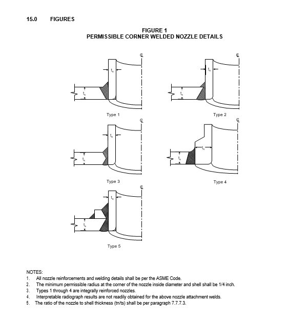
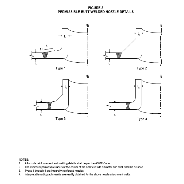
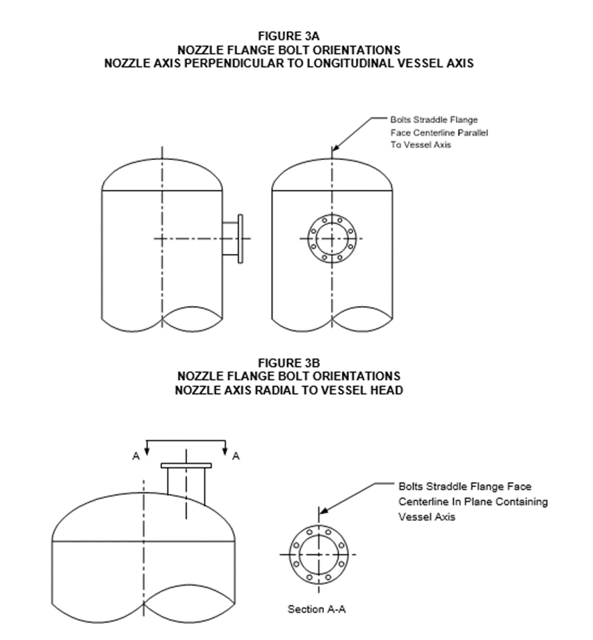
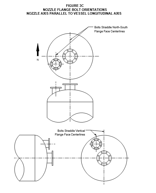
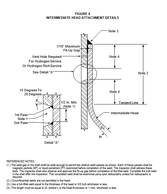
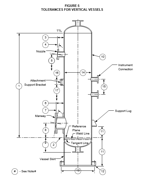
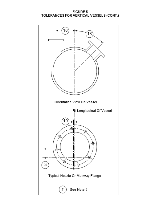
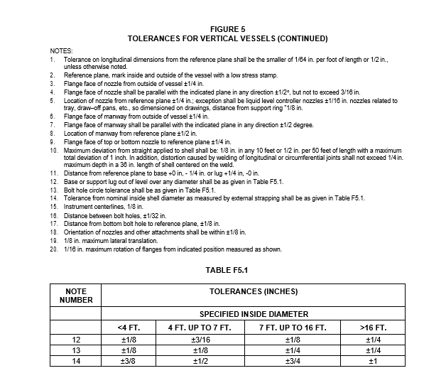
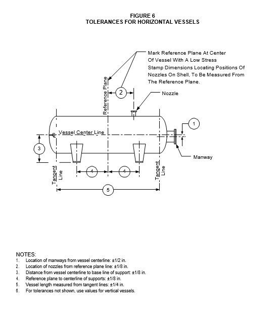
© 2026 Inflection Point Engineering, LLC. All rights reserved. The content of this page — including calculation methods, reference data, written analysis, interactive tools, and source code — is the intellectual property of Inflection Point Engineering, LLC and is protected under applicable copyright, trademark, and trade secret laws. Unauthorized reproduction, redistribution, modification, or derivative use in whole or in part is prohibited without prior written consent.
Disclaimer. This material is provided for informational and educational purposes only and does not constitute professional engineering advice. Calculations, reference data, and methodologies are based on published standards and accepted engineering practice but are not a substitute for engineering judgment, site-specific analysis, or review by a licensed Professional Engineer. Inflection Point Engineering, LLC makes no warranties, express or implied, regarding the accuracy, completeness, or fitness for a particular purpose of any content presented here, and shall not be liable for any direct, indirect, incidental, or consequential damages arising from its use. Users assume all risk associated with applying this content to real-world design, operations, or decisions.
© 2026 Inflection Point Engineering, LLC. All rights reserved.