 Section 6 — Rotating Equipment
Oil Mist Lubrication Systems - Design
IPE Engineering Practice IPE-EP-6-9-3
Document number: IPE-EP-6-9-3 · Section: 6 — Rotating Equipment
SCOPE
- This Engineering Practice covers mandatory requirements governing the vendor’s design and Purchaser’s installation of oil mist lubrication systems for machinery for lubricating bearings.
- The requirements of this Engineering Practice are applicable to other machinery applications such as purging of oil reservoirs, gear casings and bearing housings, to exclude atmospheric contamination.
- An asterisk (*) indicates that a decision by the Purchaser is required or that additional information is furnished by the Purchaser.
- Any deviation from this Practice must be approved by the procedure described in EP 1–1–3.
- Table 2 records the vendor drawing and data requirements.
- A revision bar indicates all changes made to this Revision.
2.0 REFERENCES
The latest edition of the following standards and publications are referred to herein.
STANDARDS AND PUBLICATIONS
DEFINITIONS
- Oil Mist – a dispersion of oil droplets (size 1 to 3 mm) in an air stream.
- Application Fittings (or Reclassifiers) – meter or convert oil mist to a spray.
- “Purge Mist” Lubrication – a wet sump arrangement. Normal bearing housing oil levels will be maintained and atmospheric contamination excluded by introducing oil mist.
- Dry Sump Lubrication (”Pure Mist”) – an arrangement in which no oil level is maintained in the bearing housing. Lubrication will be accomplished by condensing fresh oil from the spray on to the rolling bearing (anti–friction) elements.
- Oil Mist Lubrication System – includes the mist generator console, distribution piping with supports, application fittings, bearing housing vents, and central lubricant supply tank.
- Generator Console (as used in this Practice) – includes the oil mist generator, generator oil supply system, air supply moisture separator/filtering system, oil mist outlet header, and attendant controls and instrumentation.
DOCUMENTATION
- Proposal Information
- Proposals for the oil mist generator shall include the following information:
- Required air supply:
- Pressure - min., max. and rated, psig
- Capacity - min., max. and rated, cfm
- Total equipment list giving a description and function of each component, including materials of construction, size, capacity and utility requirements. The Manufacturer and model number of each instrument/electrical component shall be furnished.
- Details of construction including extent of shop assembly.
- List of recommended spare parts for two years continuous operation.
- Proposals for Application Fittings shall include type, size, model number and materials of construction.
- Operating and Maintenance Manuals
Manuals shall be written specifically for the oil mist generator equipment being furnished and shall contain (but not be limited to) the following information:
- Details necessary for the installation, commissioning, operation and shutdown of the unit without the need of assistance from the vendor.
- Setting and operating ranges of all instruments and controls.
- Complete bill of materials, parts list and set of final as–built drawings.
5.0 MATERIALS
Piping and tubing system components between the generator and lubrication points shall be per Table 1.
DESIGN
- General
- Application of oil mist lubrication systems for lubricating bearings, and other machinery applications will be specified.
- Oil mist lubrication systems shall not be applied for:
- Locations where the lowest average ambient temperature averages below 0 F for the four coldest, nonconsecutive, days which occurred in one year.
- Any equipment where the properties of the mist oil are incompatible with the primary lubricant.
- Equipment with force feed lubrication systems that operate continuously.
- (*) Electric motor drivers, unless specified otherwise.
- The preferred oil mist system shall be designed for dry sump lubrication.
- The oil mist generator vendor shall assume overall engineering responsibility including but not limited to selection and sizing of all system components, and approval of detail piping drawings, if used.
- Air supply shall normally be from the plant instrument air system.
- The system shall be designed to ensure a homogeneous mist at the farthest application point. The piping run between the generator and lubrication point shall not exceed the vendor’s maximum recommended limit.
- The generator shall be designed to maintain a minimum of 20 inches H2O header pressure at the generator rated flow capacity.
- All oil mist shall flow through the bearings. No continuous flowing vents are allowed that permit oil mist flow to bypass the bearings.
- Mist flow requirements per pump bearing housing must include the total number of rows of bearings and any matched back to back pair of duplex bearings.
- Certain pump manufacturers have models that allow oil mist to bypass the bearings. Contact the pump manufacturer to obtain the modifications needed to prevent bypassing when oil mist systems are installed.
- Each bearing shall include a vent on the outboard side of the bearing that will allow oil mist to discharge from the housing after it has passed through each bearing.
- Generator Console
- If a spare console is specified to be installed, the spare unit shall not be located within the same process unit area. Backup consoles shall be either part of the main console or mounted immediately adjacent to the main console.
- Enclosures for electrical equipment shall be appropriate for the specified area classification and environmental exposure.
- Generator output shall be capable of providing proper misting operation over a flow range from 50% to 115% of rated capacity at the correct header pressure.
- The generator oil reservoir shall include the following:
- A heater with temperature gauge and thermostatic control to maintain oil supply at proper viscosity.
- A level sight glass, weather protected open vent (if required), and valved low point drain.
- Automatic and manual refilling of the reservoir from an external supply tank.
- Working capacity for 48 hours operation at maximum flow.
- The following identification information shall be permanently mounted inside the generator console:
- Operating characteristics over the specified flow range
- Instrumentation set points.
- A 10 micron final filter shall be provided in the generator oil filling line.
- The vendor shall provide the design oil consumption rate in cubic inches of oil per hour per cfm of oil mist for each pump.
- The generator inlet air system shall include the following:
- An inlet air filter capable of removing particles over 10 microns and a moisture separator.
- An inlet air heater with temperature gauge, thermostatic control and automatic cut–out on heater element overtemperature.
- Distribution System Piping Layout
- Oil mist headers and laterals shall not be valved, except at central points in the mist distribution system between oil mist generator consoles if two or more consoles are operating in parallel. Unions however, are required at each oil mist console to facilitate its removal.
- Oil mist headers and branches shall be sloped to drain to the mist generator and to the equipment, respectively. The slope shall be a minimum of 1:60 for a distance of 40 feet from the generator. Beyond that distance, the slope shall be a minimum of 1:200 towards the end user.
- Tubing and piping shall be supported to limit sagging to a maximum deflection of one–half of the pipe ID. Adjustable supports are required.
- Figure 1 and Figure 2 show layout requirements for typical oil mist piping arrangements for
pump installations.
- Piping laterals shall be supported near the application fittings.
- (*) Unavoidable low points in mist headers, such as at an underground crossing, shall be drained to a knock–out pot vented to atmosphere with a rain drycoated vent. The drain line to the pot shall be fitted with an application fitting. The location of all main header drains shall be approved by the Owner’s Engineer.
- The mist distribution piping shall be sized to limit velocity to no greater than 20 ft/sec at the rated system capacity.
- The mist header shall be provided with connections at the oil mist generator console end and at header end points to permit steam cleaning and air dryout.
- Application Fittings
Fittings shall be sized and applied with mutual agreement of the machinery vendor and oil mist generator manufacturer. Sizing shall consider the requirements for proper lubrication at the minimum acceptable header pressure (low pressure alarm set point).
- Lubricant
(*) The lubricant to be used shall meet the requirements of the machinery suppliers. In the event of conflict between recommended lubricants, the selection shall be resolved with the Owner’s Engineer. A Polyalphaolefin (PAO) or ester based lubricant shall be used for centrifugal pumps and general purpose steam turbines, unless otherwise specified. Note: Paraffinic based lubricants shall not be used.
- Instrumentation
- The console shall include an oil mist header pressure gauge and relief valve sized to protect the generator components.
- Sensing devices and alarms shall be furnished for high and low:
- Air supply temperature
- Reservoir oil temperature (if oil heater is used)
- Mist header pressure
- Generator oil reservoir level
- Mist density (optional)
- Parameter levels below the low levels or above the high levels shall actuate a red light indicating alarm status. A “no alarm” status shall be indicated by a green light. Status lights shall be 60 watt minimum size and shall be mounted on top of the console.
- A connection for a remote alarm to indicate loss of electrical power or actuation of any local alarm shall be provided.
- Alarm circuits shall be “normally energized”. Alarm contacts shall open to alarm.
PIPING FABRICATION AND ASSEMBLY
- All piping joints shall be threaded. Connections shall be made–up using a Teflon paste sealant
- Cut pipe or tubing ends shall be reamed and deburred.
- Application Fittings shall not be installed until all flushing and blowing is complete and the oil mist generator is placed into operation.
- Refer to EP 6–9–4 for additional fabrication requirements.
8.0 CONSTRUCTION
(*) Oil mist generators shall be given a one hour operational test, simulating design conditions, at the Manufacturer’s shop. If specified, this test shall be witnessed.
9.0 PREPARATION FOR SHIPMENT
(*) Generator console. Painting of the cabinet for corrosive or marine atmospheres will be specified.
10.0 TABLES
TABLE 1
PIPING AND TUBING REQUIREMENTS
| Component | Material | Special Requirements |
|---|---|---|
| Piping Manifold | A120 Sch. 40 Galvanized Pipe is Standard. If extreme corrosion external corrosion, use ASTM A312 Type 304 or 316 Stainless Steel | 2” Dia. X Schedule 40 (Laterals to be of 3/4 ”Dia. X 0.065” Wall Thickness) |
| Fittings | 150# MI Galvanized Fittings are Standard. If extreme external corrosion, use ASTM A312 Type 304 or 316 Stainless Steel (Brass Fittings with 18–8 Ferrules may also be used) | |
| Tubing Fittings | 316 SS Swagelock Fittings | |
| Tubing | ASTM A304 Stainless Steel | 1/4” Minimum Diameter with a 0.035” Minimum Wall Thickness |
TABLE 2 DOCUMENTATION REQUIREMENTS
FOR OIL MIST LUBRICATION SYSTEMS - DESIGN
PER EP 6–9–3
| Item | Description | Format (1) | As–Built |
|---|---|---|---|
| 1 | Certified dimensional outline drawing and list of connections | See EP 2-5-2 | Yes |
| 2 | Cross–sectional drawing and bill of materials | See EP 2-5-2 | Yes |
| 3 | Electrical and instrumentation arrangement drawing and list of connections | See EP 2-5-2 | Yes |
| 4 | Weld procedures | See EP 2-5-2 | Yes |
| 5 | Mill test reports (certified) | See EP 2-5-2 | Yes |
| 6 | As–built data sheets | See EP 2-5-2 | Yes |
| 7 | As–built dimensions and data | See EP 2-5-2 | Yes |
| 8 | Installation manual | See EP 2-5-2 | Yes |
| 9 | Operating and maintenance manuals | See EP 2-5-2 | Yes |
| 10 | Spare parts recommendation | See EP 2-5-2 | Yes |
| 11 | Fabrication and delivery schedule | See EP 2-5-2 | Yes |
| 12 | Drawing list | See EP 2-5-2 | Yes |
| 13 | Shipping list | See EP 2-5-2 | Yes |
NOTE:
(1) If the document cannot be provided in the format as indicated, the Manufacturer shall consult with the Owner’s Engineer for an acceptable alternative.
FIGURES
FIGURE 1
OIL MIST LUBRICATION SYSTEM TYPICAL APPLICATIONS (DIAGRAMATIC LAYOUT OF PIPING)
Distribution Block Or Tees (Typical)
Top Connection (Typical)
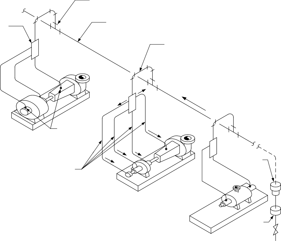
Mist Header (NPS 2 In. Min.)
Lateral
(NPS 3/4 In. Min.)
Drain System For Unavoidable Low Spots
Slope
Single Bearing Housing Pump And Motor
Reclassifier Fittings (Typical)
Reclassifier
1/4 In. Tubing Bearing 0.035 In. Wall (Typical)
Pump And Turbine
Fitting
Two Bearing Housing Pump
Drain Pot
(optional)
| Linear (Feet) |
Dimensions (MM) |
Pipe And Tubing Sizes (NPS Or OD As Indicated) (Inches) (MM) |
Pipe And Tubing Sizes (NPS Or OD As Indicated) (Inches) (MM) |
|---|---|---|---|
| 2 | 600 | NPS 3/4 | 19 |
| 3 | 900 | NPS 2 | 50 |
| 1/4 OD | 6 |
FIGURE 2
“PURGE MIST” WITH SIGHT LEVEL ASSEMBLY


Benefits of Purge Mist (Also called “Wet Sump”)
- Keeps Oil Free From Contamination
- Continuously Coats All Internal Surfaces with Lubricant
- Make-Up Oil is Continuously Delivered to the Sump
FIGURE 3
PURE MIST “DRY SUMP” APPLICATION DETAIL
© 2026 Inflection Point Engineering, LLC. All rights reserved. The content of this page — including calculation methods, reference data, written analysis, interactive tools, and source code — is the intellectual property of Inflection Point Engineering, LLC and is protected under applicable copyright, trademark, and trade secret laws. Unauthorized reproduction, redistribution, modification, or derivative use in whole or in part is prohibited without prior written consent.
Disclaimer. This material is provided for informational and educational purposes only and does not constitute professional engineering advice. Calculations, reference data, and methodologies are based on published standards and accepted engineering practice but are not a substitute for engineering judgment, site-specific analysis, or review by a licensed Professional Engineer. Inflection Point Engineering, LLC makes no warranties, express or implied, regarding the accuracy, completeness, or fitness for a particular purpose of any content presented here, and shall not be liable for any direct, indirect, incidental, or consequential damages arising from its use. Users assume all risk associated with applying this content to real-world design, operations, or decisions.
© 2026 Inflection Point Engineering, LLC. All rights reserved.