 Section 6 — Rotating Equipment
General Purpose Lube Oil Systems
IPE Engineering Practice IPE-EP-6-9-2
Document number: IPE-EP-6-9-2 · Section: 6 — Rotating Equipment
GENERAL
- Scope
- This Practice covers the minimum requirements for lubrication oil systems used in general- purpose applications. For special-purpose lube/seal oil systems, EP 6-9-1 shall be applied.
- When this Practice is specified in the purchase order or on data sheets included with the purchase order, this Practice shall take precedence over any other section of any other API standards that covers the same subject.
- Additional requirements and detailed design data shall be specified on the attached general- purpose lube oil system data sheets.
- All exceptions taken to this Practice and the data sheets, shall be clearly stated in the vendor proposal.
- Bulleted items can be considered if this EP is used for reciprocating compressors or integrally-geared centrifugal air compressors.
- An asterisk (*) indicates that a decision by the Owner or Owner's Engineer is required, or that additional information is to be furnished by the Purchaser.
- Any deviation to this Practice must be approved by the procedure described in EP 1-1-3 before the proposal is considered technically acceptable.
- The vendor shall accept full responsibility for the design, construction, and conformance to the referenced specifications, regulations, and requirements as specified in the purchase order. Furthermore, it is the vendor's responsibility to request from the purchaser any missing documents/ Engineering Practices which are not attached nor specified, but required in the requisition.
- The vendor shall be responsible for insuring that the design of equipment for the entire lube/seal oil system(s) regardless of sources are compatible with each other, dimensionally and in performance and control, so that a fully integrated unit is achieved.
- Alternative Designs
- The vendor may offer alternative designs for consideration if they are more cost effective while meeting the technical requirements.
- Metric fasteners and flanges constitute alternative design features and must be cited as exceptions in the vendor proposal.
- Conflicting Requirements
- In case of conflict among the various documents, their order of precedence is generally as follows:
- Purchase Order
- Data Sheets
- Project Specification(s)
- Referenced Industry Standards
- All conflicting requirements shall be referred to the Purchaser in writing prior to issuance of the purchase orders and/or before proceeding with the manufacture of the part(s) under question. The Purchaser will issue confirming documentation if needed for clarification.
- Mandatory requirements cannot be superseded by any of the foregoing, and compliance therewith will be the joint responsibility of Purchaser and Vendor. Mandatory requirements include all codes, regulations, ordinances, and statutes of all municipal, state and national bodies having jurisdiction in the locations where the equipment is to be installed. It shall be the vendor's responsibility for discernment and compliance with those mandatory requirements.
- Definition of Terms
Terms used in this Practice are defined as follows.
- Continuous-Flow Transfer Valve - can simultaneously divert both inlet and outlet without altering the continuity of full flow through the valve to equipment.
- Maximum Allowable Working Pressure - the maximum continuous pressure for which the Manufacturer has designed the console or components when handling the specified fluid at the specified pressure.
- Normal Operating Point - the point at which usual operation is expected and optimum efficiency is desired. This point is usually the point at which the vendor certifies that performance is within the tolerances stated in this Practice.
- Manufacturer - the recipient of a direct or indirect purchase order for materials and/or equipment. In this context, a direct order is one issued to a manufacturer by a contractor or the Owner. An indirect order is one issued to a manufacturer by a vendor (recipient of a direct order) for materials, fabricated components, or subassemblies.
- Maximum Operating Level - the highest level in the oil reservoir that oil should be allowed to reach during normal operation of the equipment.
- Minimum Operating Level - the lowest level in the oil reservoir that oil should be allowed to reach during normal operation of the equipment.
- Retention Time - the time allowed for disengagement of entrained air or gas.
- Inspector - a Company appointed engineer or inspector.
- Owner - Company.
- Owner's Engineer - A Company appointed engineer.
- Purchaser - The party placing a direct purchase order. The Purchaser is the Owner's designated representative.
- Referenced Publications
- The referenced Engineering Practices, and any other attached to the requisition shall apply to the extent referenced herein or on the data sheets.
- The editions of the following standards, codes, and specifications that are in effect at the time of publication of this Practice shall, to the extent specified herein, form an integral part of this practice. The applicability of changes in standards, codes, and specifications that occur after the inquiry shall be mutually agreed upon by the Purchaser and vendor.
STANDARDS AND PUBLICATIONS
| Engineering Practices |
|---|
| EP 1-1-3 Deviations to Engineering Practices EP 5-6-2 Piping for Rotating Equipment EP 6-3-1 General Purpose Steam Turbines EP 6-7-1 Special Requirements for Rotating Equipment EP 6-8-1 Field Storage and Installation of Rotating Equipment EP 8-1-2 TEMA Shell and Tube Heat Exchangers for Non-Process Services EP 12-1-1 Control Systems EP 12-2-1 Control Systems Installations EP 13-3-1 Induction Motors 500 HP and Below EP 13-13-1 Electrical Standards for Packaged Equipment |
| ANSI Standards |
| Y14.2M Line Conventions and Lettering |
| API Standards |
| Std 676 Positive Displacement Pumps - Rotary |
| ASME Standards |
| B31.3 Chemical Plant and Petroleum Refinery Piping Boiler & Pressure Vessel Code, Section V, "Nondestructive Examination"; Section VIII, "Pressure Vessels", Division 1 and 2; Section IX, "Welding and Brazing Qualifications" |
| AWS Standards |
| D1.1 Structural Welding Code - Steel |
BASIC DESIGN
- General
- The vendor shall assume responsibility for the engineering coordination of the equipment and all auxiliary systems included in the scope of the order.
- (*) The system shall be designed to supply lube oil to all equipment specified by the Purchaser.
- When the system is designed to supply lube oil to two or more machines (such as a pump, a motor, or a gear), the vendor having total unit responsibility shall indicate the oil's characteristics on the data sheets.
- The unit and its auxiliaries shall be suitable for operation under the environmental conditions as specified on the data sheets. The vendor shall list in the proposal any special protection or operating restrictions with which the Purchaser must comply or which the Purchaser must provide.
- Oil pumps shall be adequately sized for the required service. The required head and capacity shall be calculated so that allowances for back pressure regulators, pressure drops due to dirty filters and coolers are taken into account.
- (*) When specified, valved vents, drains, and crossover piping and valves shall be furnished between dual equipment items to permit draining, cleaning, and refilling of idle components while the active equipment is in operation.
- (*) Coolers, filters, and other pressure vessels within the scope of Section VIII of the ASME Code shall conform to the code and shall be code stamped, if specified by the purchaser on the data sheets.
- Piping, filters, and reservoirs shall be grounded, as necessary, to prevent static electrical charge build-up.
- The arrangement of components, including piping, valve locations, customer connections, and auxiliaries, shall be developed jointly by the Purchaser and the vendor. The arrangement shall provide adequate clearance areas and safe access for operation and maintenance. Special design consideration shall be given to assure sufficient clearance around and access to oil pumps, motors, coolers, filters, and hand valves, e.g. clearance to turn valves, read gauges, service filters, and remove bundle.
- The discharge end of all drain and vent lines shall be readily visible to an operator standing at the location of the drain or vent valve. Level gauges, pressure and temperature indicators used to aid in the adjustment of a valve shall be suitably located so as to be clearly visible from the valve location.
- Valves that are frequently operated or adjusted during operation shall be located so that they can be easily accessible from grade or platform.
- As a minimum, the lube oil system shall include all components as shown in Figure 1 for a typical schematic.
- Baseplates
- (*) Unless otherwise specified by the Purchaser, the system shall be designed as a single or multiple package. Each package shall have a structural steel baseplate with all system components and related valves and manifolds mounted on the baseplate. Oil pumps, filters, coolers, and reservoir shall be mounted directly on structural steel.
- Package baseplates shall be furnished with single-piece drain-rim or drain-pan around. To facilitate complete drainage, the rim or pan of the baseplate shall be sloped 1/8 inch per foot toward one or more taped drain openings at least NPT 1-1/2 inches in size. Baseplates, mounted components, and decking shall be arranged and installed to insure complete drainage and avoid the collection and retention of liquid.
- (*) Unless otherwise specified on the data sheets, the top of the baseplate shall be completely covered by steel decking such as checker or diamond plate.
- All personnel access, walkways and work areas, if any, on the baseplate shall be fully covered with non-skid 1/4 inch thick, hot dipped galvanized serrated grating. The grating shall be securely attached to provide safe footing for personnel. Clips and bolting hardware shall be of stainless steel.
- The baseplate shall be equipped with lifting lugs to allow at least a four-point lift. The baseplate shall be suitably designed so that the package, without oil, can be safely lifted without permanently distorting or otherwise damaging either the baseplate or any component mounted on the baseplate.
- (*) Unless otherwise specified, anchor bolt holes and vertical leveling screws spaced for stability shall be provided on the outside perimeter of the baseplate. The amount of leveling screws shall be adequately selected to carry the weight of the entire baseplate and all components mounted on it without excessive deflection. As a minimum, six (6) leveling screws shall be furnished.
- The bottom of the baseplate between structural members shall be open. When the baseplate is to be installed on a concrete pad, adequate accessibility shall be provided for grouting under all load-carrying members.
- (*) Unless otherwise specified on the data sheets, all baseplates shall be furnished with at least one grout hole in each bulkhead section. Grout holes shall be round, at least 4 inches in diameter. These holes shall be strategically located to permit filing of the entire cavity under the baseplate without creating air pockets. All grout holes shall be completely accessible for grout placement. Grout holes shall have 1/2 inch raised-lip edges. Vent holes at least 1/2 inch in diameter shall be drilled for each bulkhead compartment.
- All welding shall be performed in accordance with AWS D1.1, except for welding covered by Section VIII, Division I, of the ASME Code and ASME B31.3.
- (*) When epoxy grout is specified on the data sheets, the vendor shall pre-coat the entire underside of the baseplate with a catalyzed epoxy primer applied to degreased white metal.
- Oil Reservoir
- (*) Oil reservoirs shall be sufficiently designed and built to prevent sagging and vibration. When, with the Purchaser's approval, pumps, coolers, or filters are mounted on the reservoir, they shall be mounted on pads; no bolt holes shall be extended into the reservoir.
- (*) Reservoirs and all appendages welded to reservoirs shall be fabricated from AISI Standard Type 300 stainless steel in accordance to ASTM A 240, as agreed upon by the Purchaser and the vendor.
- Reservoirs shall be properly sized to allow enough capacity for system rundown; to provide a retention time of at least 4 minutes to adequately settle trapped dirt and moisture, and to avoid frequent refilling
- Reservoirs shall be sealed to prevent dirt and water from entering. Top-surface openings shall be raised at least 1 inch and shall have a gasket.
- All oil return connections shall be located hydraulically as far away from the pump suction connections as possible to minimize flow disturbance at the pump inlets.
- Necessary provisions shall be made to eliminate aeration and static electricity. A vertical baffle, separating the suction and return sides, shall be provided in the reservoir. All pressurized oil return connections shall be separate and shall discharge oil via internal piping below the pump suction-loss level.
- To insure complete drainage, the bottom of each reservoir shall be suitably sloped, not less than 1/4 inch per foot, to a low point where a flanged and valved drain connection at least NPS 1 inches in size shall be provided.
- Pump suction connections shall be located near the high end of the sloped reservoir bottom.
- Cleanup openings/manways as large as practicable shall be strategically located to facilitate cleaning of the oil reservoir.
- A fill opening, at least 2 inches in size, equipped with a stainless steel fine-mesh basket strainer that has an open area equal to 200 percent of the internal pipe area shall be provided.
- A reflex-type oil level glass located as far away from the oil returning lines as possible shall be provided. The maximum and minimum operating levels shall be visibly indicated.
- A filter-breather cap suitable for outdoor use shall be provided.
- Pipe connections to the reservoir shall be flanged.
- (*) When specified, threaded and plugged connections used for such services as purge gas and makeup oil supply shall be provided. These connections should be located above the rundown oil level.
- (*) Unless otherwise specified, a thermostatically controlled electric immersion heater with a sheath of AISI Standard Type 300 stainless steel shall be supplied for heating of the charge capacity of oil before startup in cold weather. The heater shall be capable of heating the oil in the reservoir form the specified minimum site ambient temperature to the Manufacturer's required startup temperature within 12 hours. Electric immersion heaters shall have a maximum watt density of 15 watts per square inch. If steam heaters are used in the space below the sloped reservoir bottom, provision shall be made to fill this space with a heat transfer fluid. In this case, a vented standpipe sized to accommodate temperature-dependent volume expansion shall be provided as well.
- Electric immersion oil heaters should be interlocked to de-energize when the oil level drops below the minimum operating level.
- Joints, pads, and connections shall be both internally and externally welded to eliminate cavities, potential sources of corrosion, and contamination. The wall-to-top junctions may be welded from the outside if a full-penetration weld is used. Internal welded joints shall be suitably smoothed out to eliminate pockets.
- Pumps, Drivers and Lube Oil Systems
- (*) The oil system shall include a main oil pump and an auxiliary oil pump. Unless otherwise specified, the auxiliary oil pump shall be motor-driven and shall be equipped with an automatic/manual control system set up to start automatically on low oil pressure and with manual shutdown only.
- (*) Unless otherwise specified, oil pumps shall be of the positive displacement type and shall comply with API Standard 676. Rated capacity should be at least 150 percent of the total flow required by equipment this oil system serves.
- (*) Oil pumps shall have steel casings and all other oil-containing pressure components shall be steel, unless otherwise specified by the purchaser.
- Electric motors shall conform to EP 13-3-1.
- Steam turbines shall comply with EP 6-3-1. The pump as well as the total system shall be capable of operating up to the overspeed trip setpoint. Steam turbines shall be equipped with removable blanket type insulation.
- Check valves shall be provided on each pump discharge to prevent the flow of oil backwards through a standby or idling pump. Swing check valves having low pressure drop are preferred. If used, swing check valves should not be installed in a vertical position.
- An external pressure relief valve shall be provided for each oil pump. The pressure relief valve shall be located on the pump discharge line between the pump nozzle and the check valve or the first block valve, whichever is closer to the oil pump. Discharge from the pressure relief valve shall be individually piped back to the oil reservoir.
- Pressure relief valves shall be located as close to the oil pump discharge as possible at an elevation near or below the minimum operating level as practical.
- Relief valve piping shall be sized for full flow of each pump; the valves shall not chatter, and the piping shall not vibrate. The minimum relief valve set pressure shall be 10 percent or 25 PSI higher than the highest required operating pressure, whichever is greater.
- The lube oil system shall be supplied with pressure regulating devices/pressure control valves that prevent fluctuation of oil pressure to the equipment when both the main and the auxiliary pump are in operation or when either the main pump or the auxiliary is in operation and the other pump is started or stopped. Each device shall have an adequate response time and shall operate smoothly without hunting, chattering, or producing pressure or flow transient that cause either the equipment to shut down or the relief valve to open.
- Pressure relief valves shall not be used for continuous pressure regulation. Back pressure regulators should be located upstream of the oil coolers.
- (*) Unless otherwise specified, a permanent Y-type basket strainer shall be installed in the suction piping of each externally mounted pump. The basket shall be made of 304 or 316 stainless steel and shall have an open flow area equal to 150 percent of the cross-sectional area of the suction pipe.
- All pumps (except shaft-driven pumps) shall be installed with flooded suctions to insure self- priming. Shaft-driven pumps shall have adequate provision for priming. Each pump shall have a separate suction line, having a gate/foot valve, from the reservoir and shall be installed with a separate discharge check valve.
- Couplings and guards between pumps and drivers shall be supplied by the vendor. Removable, non-sparking coupling guards built in compliance with the OSHA requirements shall be furnished.
- Couplings and coupling-to-shaft junctures shall be rated for at least the maximum driver power (including any motor service factor). Couplings shall be keyed in place.
- Mounting plates shall be provided as following:
- Mounting pads shall be provided for each pump and its driver. The pads shall be machined flat and parallel to eliminate soft-foot problems to the equipment. Pads shall be at least 1/2 inches thick.
- All pads for oil pumps and drivers shall be machined to better than 63 RMS surface finish, leveled to within 0.002 inch per foot, and co-planner within 0.002 inch per foot of distance between pads.
- For coupling alignment purpose, a set of stainless steel shims at least 1/8 inch thick shall be furnished under the feet of each equipment. No more than six shims shall be allowed in one stack. Equipment hold-down bolt holes shall have at least 1/8 inch radial clearance from bolts.
- To minimize coupling misalignment due to piping load effects, the pump and its baseplates shall be constructed with sufficient structural stiffness and the connecting piping system shall be adequately and independently supported to avoid excessive piping strains on the pumps.
- (*) When specified, or if the main and auxiliary are installed in the console (main oil pump is not shaft driven), a piping fit-up shall be done in compliance with the procedure given in
EP 6-8-1. This inspection shall be witnessed by 's Inspector
- Coolers
- (*) Unless otherwise specified, a water-cooled shell-and-tube type oil cooler shall be provided. Oil coolers shall comply with EP 8-1-2.
- (*) If dual coolers are specified, they shall be piped in parallel arrangement using a continuous-flow transfer valve.
- Internal oil coolers are not acceptable.
- Each oil cooler shall be designed to maintain the lube-oil supply temperature at or below 120oF, unless otherwise specified by the equipment vendor.
- (*) Water-cooled shell-and-tube type coolers shall have water on the tube side. Unless otherwise specified, the oil-side operating pressure shall be higher than the water-side- operating pressure to prevent the oil from being contaminated, if the cooler fails.
- (*) Unless otherwise specified, a removable-bundle design is required for shell-and-tube coolers with more than 5 square feet of surface. Removable-bundle coolers shall be constructed with a removable channel cover.
- Coolers shall be equipped with vent and drain connections on oil and water sides to permit complete drainage.
- Tubes shall have an outside diameter of not less than 5/8 inch, and the minimum tube wall thickness shall be 18 Birmingham Wire Gage (BWG) inch.
- (*) Unless otherwise specified, cooler shells, channels, and covers shall be made of steel; tube sheets shall be made of naval brass; and tubes shall be made of inhibited admiralty.
- The minimum design pressure for oil coolers shall not be less than the maximum operating pressure of the system, or less than the relief valve setting for the oil pumps.
- (*) When specified, the coolers shall be suitably designed and built for use of a heating medium, such as low-pressure steam or a mixture of steam and water.
2.6 Filters
2.6.1
2.6.2
2.6.3
2.6.4
2.6.5
2.6.6
2.6.7
2.6.8
2.6.9
2.7
2.7.1
2.7.2
2.7.3
2.7.4
2.7.5
Twin full-flow filters located downstream of the oil cooler and piped in a parallel arrangement using a continuous-flow transfer valve shall be provided.
(*) Filters shall have replaceable elements or cartridges with filtration of 10 microns nominal or finer, unless otherwise agreed to by . Filter cartridge materials shall be corrosion resistant. Metal mesh or sintered-metal filter elements are not acceptable.
Filters that have covers weighing more than 35 pounds shall be equipped with cover lifters.
When tops of the filters are more than 4 feet above the console base, the vendor shall provide an elevated deck to facilitate their service and maintenance.
Filters shall not be equipped with relief valves or other valves that can allow bypass of unfiltered oil around the filter elements.
Valved vents and clean- and dirty-side valved drain connections shall be furnished. The dirty- side connections shall be located lower in the housing than the filter elements or cartridge support bases.
Filter cases and heads shall be suitable for operation at a pressure not less than the relief valve setting of the oil pumps.
Oil filter design shall incorporate the following features:
- Oil flow from the outside inward toward the center of the filter element.
- The ability to completely drain oil from the filter housing while avoiding contamination of the downstream (clean) side with unfiltered oil during replacement of the filter elements.
- Consideration of the use of guard elements (such as filter element fibers) to capture debris in case of filter element deterioration or failure.
The pressure drop for clean filter elements or cartridges shall not exceed 5 psi at an operating temperature of 100oF and normal flow. Elements or cartridges shall have a minimum collapsing differential pressure of 70 psi.
Transfer Valves
- (*) When specified, transfer valves shall be two-way, six-ported continuous-flow valves. Typically, one single-body, six-port taper or straight plug valve may be used, or two three-way plug or ball valves permanently aligned and joined with a single operating level may be used. Tapered plug-type valves shall have provisions for plug lifting.
Transfer valves shall have steel bodies. Valve plugs or balls shall be made of stainless steel.
Transfer valves shall be designed so that, if the internal valve mechanisms fail, both flow paths will not be blocked.
Transfer valves shall be equipped with an indicator showing the flow path to help positively identify which filter or cooler is being used.
- (*) When specified, spectacle blinds shall be provided by the vendor to assure tight shutoff of oil flow for maintenance of oil coolers and filters.
- Piping
- The vendor shall furnish all piping systems, including mounted appurtenances, located within the confines of the main unit's base area, any console area, or any auxiliary base area. The Purchaser will furnish only interconnecting piping between equipment groupings and off-base facilities.
- The piping for interconnecting piping between packages, for air, water, steam, and the utility services to a package, and for other Purchaser's connection to the packages shall terminate with flanged connections at the edge of the base. Instrument tubing connections shall terminate with NPT connections.
- Piping and component drains and vents less than or equal to NPS 1-1/2 inch shall terminate with a plugged drain or vent valve accessible from the edge of the base or a work area.
- Piping shall be fabricated preferably by bending and welding to minimize the use of flanges and fittings. Threaded connections shall be held to a minimum. Pipe bushings and close nipples shall not be used.
- Piping design, joint fabrication, installation and inspection shall be in accordance to ASME 31.3 and EP 5-6-2.
- All lube oil piping including the oil reservoir shall be 304 stainless steel.
- (*) Piping arrangements shall be designed for ease of maintenance. Flange breaks shall be strategically located to facilitate removal of any component/equipment for service. When specified, block valves shall be installed in the suction and discharge piping of the auxiliary oil pump. "Low point" drain valves shall be provided to allow complete drainage of the lube oil.
- Combination stop/check valves shall not be used.
- Gaskets and packings for flanges, valves, and other components shall not contain asbestos.
- Oil drains shall be sized to run no more than half full when flowing at a velocity of 1 foot per second and shall be strategically arranged to assure good drainage. Horizontal runs shall slope continuously at least 1/2 inch per foot. The minimum size for oil drains shall be NPS 1-1/2.
INSTRUMENTATION, CONTROL, AND ELECTRICAL SYSTEMS
- General
- (*) The lube oil system shall be adequately and suitably instrumented and controlled for orderly startup, stable operation, warning of abnormal conditions, and, if specified, shutdown of the main equipment in the event of impending damage.
- Instrumentation and control systems shall comply with EP 12-1-1 and EP 12-2-1.
- (*) Unless otherwise specified, all instrumentation and controls shall be suitable for outdoor installation.
- All controls and instruments shall be located and arranged to allow clear visibility by the operators, as well as easy accessibility for tests, adjustments, and maintenance.
- Piping, tubing and conduits that require insulation shall be arranged to provide adequate clearance for installation of insulation.
3.2
3.2.1
3.2.2
3.2.3
3.2.4
3.2.5
3.2.6
3.3
3.3.1
3.3.2
3.3.3
3.3.4
- (*) When specified, except for instrument air service, bleed valves are required between instruments and their isolation valves. Combination isolation/bleed valves are acceptable.
Individual tubes or groups of individual tubes shall be continuously supported in conduit or angle iron. Wiring or attaching to a pipe is NOT acceptable.
Each instrument shall be permanently tagged with the item number and service. Teflon tape shall not be used; however, Teflon paste compounds may be used.
- (*) All control valves shall be flanged. Unless otherwise specified, they shall be equipped with isolating valves, and NPS 3/4 inch bleed valves.
Oil heaters shall have thermostats set to limit oil temperature in the reservoir to the value recommended by the equipment vendor, normally 120oF or less.
Instrument Gauge Boards and Panels
- The specified instruments for the console and equipment may be local or gauge board mounted. Gauge boards shall be designed and fabricated in accordance to the Purchaser's description.
- (*) When specified by the Purchaser, a panel shall be provided in place of or in addition to any specified gauge board and shall include panel-mounted instrument for the equipment served by the oil system. Unless otherwise specified, the panel shall be freestanding and enclosed, and shall have a weather hood and light.
The instruments on the gauge board and panel shall be individually labeled and clearly visible to the operator from the driver control point.
Gauge boards and panels shall be completely piped and wired, requiring only connections to the Purchaser's external piping and wiring circuits. When more than one wiring point is required on a unit for controls or instrumentation, wiring to each switch or instrument shall be provided from terminal posts in a single terminal box which is mounted on the unit or its base, if any.
(*) Instrument connections shall terminate at locations specified by the Purchaser.
All wiring shall be installed in metal conduit or enclosures. All leads and posts on terminal strips, switches, and instruments shall be tagged for identification purposes.
Alarms and Shutdowns
(*) As a minimum, the vendor shall furnish and mount the alarm and shutdown contacts as specified on the data sheets.
(*) Switches, control devices, and annunciator display units shall be furnished and mounted by the vendor as specified by the Purchaser.
(*) Unless otherwise specified, each alarm switch and each shutdown switch shall be furnished in a separate housing located to facilitate inspection and maintenance. Switch settings shall not be adjusted from outside the housing.
Alarm and shutdown devices shall function directly, not indirectly through a control panel, and shall be suitable for operation on both alternating current (AC) and direct current (DC).
- As a minimum, switches shall have dry-type, single-pole, double-throw contacts with a resistive rating of 5 amperes at 120 volts AC, and 1/2 volts at 120 volts DC. Each switch shall be independently adjustable.
- Alarm and trip switches shall be arranged to permit testing of the control circuit, including, when possible, the actuating element, without interfering with normal operation of the equipment. Shutdown switches without isolation valves must be tested with the equipment in a non- operating mode.
- Low-pressure (failing) alarms shall be equipped with valved bleed or vent connections to allow controlled depressurization and accurate determination of the alarm set pressure on the associated pressure gauge.
- The vendor shall furnish a clearly visible light on the panel to indicate when trip circuits are in a test bypass mode.
- (*) Unless otherwise specified, shutdown systems shall be provided with electrical disconnect switches or another suitable means to permit testing without shutdown the main equipment.
- The vendor shall furnish with the proposal a complete description of the alarm and shutdown facilities to be provided.
- When the shutdown system contains more than one shutdown, the system shall have a "first out" indication.
- Instrumentation
- Thermometers and Thermowells
- Thermometers shall be heavy-duty, bimetallic with a 5 inch adjustable angle dial face and stainless stain case. Black printing on a white background is standard for gauges.
- Thermometers shall be provided in the reservoir, in the oil piping downstream of the coolers, and in the oil outlet from each bearing on the equipment served by the oil system.
- Temperature-sensing elements shall be in the flowing fluid. This is particular important for drain lines from the bearings where the oil may run partially full.
- All thermometers and temperature-sensing elements except those located in atmospheric drain lines shall be furnished with NPT 3/4 inch AISI Standard Type 300 stainless steel separable solid-bar thermowells. Pipe sections where a thermowell may restrict oil flow shall be locally enlarged.
- Thermowells on insulated lines and the reservoir shall have a 2-1/2 inch extension neck.
- Pressure Gauges
- (*) Pressure gauges shall be furnished at the discharge of each oil pump, at the control inlet (supply) oil header, and at other locations as specified by the Purchaser on the data sheets or oil system schematic.
- The pressure gauge at the pump discharge shall be located upstream of the check and block valves and shall be readily visible from the discharge block valve.
- A differential pressure gauge to measure the oil filter pressure drop shall be provided between the inlet and outlet of oil filters.
- Pressure gauges shall be of the safety-front type. Each gauge shall be equipped with a safety blowout disk to relieve excess case pressure.
- Pressure gauges shall have 4-1/2 inch dials and NPT 1/2 inch male Type 316 stainless steel connections. Dials shall be white with black printing.
- Gauge range shall be selected so that the normal operating pressure is at the middle of the gauge. The maximum reading on the dial shall be greater than the applicable relief valve setting plus 10 percent.
- All process (oil) pressure connections shall be 3/4 inch minimum with at least a 3/4 inch block valve.
- Orifices shall be provided in the instrument piping to protect pressure gauges from sudden pressure surges. All orifice unions and restrictive orifice plates shall be stamped or permanently identified with their size and part number.
- (*) When specified, pressure gauges shall be equipped with bleed and block valves.
- Flow Indicators
- Flow indicators shall be provided in the oil-drain return line from each bearing.
- (*) Unless otherwise specified, the flow indicator shall be flanged, of bull's-eye type, and shall have stainless steel body.
- Each flow indicator shall be installed with its bull's eye in a vertical plane.
- Relief Valves
- The vendor shall furnish the relief valves that are to be installed on the components or in piping that the vendor is supplying.
- The vendor shall determine the size and set pressure of all relief valves associated with the system components. Relief valve settings shall take into consideration all possible types of equipment and component failures and the protection of the oil system piping and components.
- (*) When specified, thermal relief valves shall be provided for components that may be blocked in by isolation valves.
- Relief valves shall have steel bodies, flanges and shall be mounted vertically in an upright position.
- Relief valves of modulating type shall be used.
- Electrical Systems
- (*) Electrical equipment located on the unit or on any separate panel shall be suitable for the hazard specification specified on the data sheets.
- Power, control, and instrument wiring within the confines of the baseplate shall be resistant to oil, heat, moisture, and abrasion. Wiring shall be suitable for environmental temperatures.
- (*) When specified, electrical systems shall comply with EP 13-13-1. For general purpose lube oil systems, the only applicable Engineering Practices listed in paragraph 2.0 of EP 13-13-1 are EP 1-1-3, EP 12-1-1, EP 13-2-1, EP 13-3-1, EP 13-8-1 and
EP 13-14-1.
- Control, instrumentation, and power wiring within the limits of the baseplate shall be installed in rigid metallic conduits and boxed, properly bracketed to minimize vibration and isolated or shielded to prevent interference between voltage.
- For Division 2 locations, flexible metallic conduits shall have a liquid tight thermosetting or thermoplastic outer jacket and approved fittings. For Division 1 locations, UL approved flexible fittings shall be provided.
- (*) Unless otherwise specified, all leads on terminal strips, switches, and instruments shall be permanently tagged for identification.
INSPECTION, TESTING, AND PREPARATION FOR SHIPMENT
- General
- After advance notification of the vendor by the Purchaser, the Purchaser's representative shall have entry to all vendor and sub-vendor plants where manufacturing, testing or inspection of the equipment is in progress.
- (*) The vendor shall notify the Purchaser in writing at least five working days before the date the equipment will be ready for any witnessed or observed inspection or test as specified by the Purchaser.
- Witnessed means that a hold shall be applied to the product schedule and the inspection or test shall be carried out with the Purchaser's inspector in attendance. The vendor shall notify the Purchaser of a schedule for witness test only after an in-house, preliminary test was successfully conducted.
- Observed means that the Purchaser shall be notified of the inspection or test; however, the inspection or test shall be performed as scheduled, and if the Purchaser's Inspector is not present, the vendor shall proceed to the next step.
- (*) When shop inspection and testing have been specified by the Purchaser, the Purchaser and the vendor shall meet to coordinate manufacturing hold points, inspector's visits, and inspection requirements.
- The Purchaser's Inspector shall have the right to reject any console or console components that do not conform to the purchase order.
- Inspection
- The vendor shall keep the following data available for at least 2 years for examination by the Purchaser upon request.
- Necessary certification of materials, such as mill test reports.
- Purchase specifications for all items on bills of materials.
- Test data to verify that the requirements of the specifications have been met.
- Results of documented tests and inspections, including fully identified records of all heat treatment and radiography.
- Radiography inspection shall be in accordance with ASTM E 94 and ASTM E 142. The acceptance standard used for welded fabrications shall be Section VIII, Division 1, UW -52, of the ASME Code.
- Magnetic particle inspection shall be in accordance with ASTM E 709. The acceptance standard used for welded fabrications shall be Section VIII, Appendix 6, of the ASME Code.
- Liquid penetrant inspection shall be in accordance with Section V, Article 6, of the ASME Code. The acceptance standard used for welded fabrications shall be Section VIII, Division 1, Appendix 7, of the ASME Code.
- Testing
- General
- At least 6 weeks before the first scheduled test, the vendor shall submit to the Purchaser, for his review and comment, detailed procedures for all running tests, including acceptance criteria for all monitored parameters.
- The vendor shall notify the Purchaser, in writing, at least five (5) working days before any witness test dates. If the test date is rescheduled, the vendor shall notify the Purchaser not less than three (3) working day before the new test date.
- (*) Unless otherwise specified, equipment shall be tested in accordance with paragraphs 4.3.2 and 4.3.3.
- The Purchaser shall specify whether the purchased oil system shall be used in the shop testing of the equipment.
- Hydrostatic Test
- Pressure-containing parts (including auxiliaries) shall be hydrostatically tested with liquid at a minimum of 150 percent of the maximum allowable working pressure, but not less than 20 PSIG. The assembled oil system, or each package, shall also be tested hydrostatically using oil compatible with the system oil.
- If the parts tested are to operate at a temperature at which the strength of a material is below the strength of that material at room temperature, the hydrostatic test pressure shall be multiplied by a factor obtained by dividing the allowable working stress for the material at room temperature by that at operating temperature. The stress values used shall conform to those given in ASME Code for vessels. The pressure thus obtained shall then be the minimum pressure at which the hydrostatic test shall be performed.
- The chloride content of liquid used to test austenitic stainless steel materials shall not exceed 50 parts per million. To prevent deposition of chlorides as a result of evaporative drying, all residual liquid shall be removed from tested parts after the test is concluded.
- Hydrostatic tests shall be maintained for a sufficient period of time to permit complete examination of parts under pressure. The test shall be considered satisfactory when neither leaks nor seepage through the casing, casing joints, or flange gaskets is observed for a minimum of 30 minutes.
- The actual hydrostatic test pressures and the test duration shall be listed on the data sheets and test certifications.
- Operational Tests
- The complete oil system shall be run in the vendor's shop to test its operation and cleanliness. The oil used shall be compatible with the recommended system oil.
- System cleanliness shall be demonstrated and verified by the vendor before the operational test.
- The running test shall be conducted under normal system operating conditions for at least four
(4) hours.
- All oil pressures, viscosities, and temperatures shall be within the range of operating values recommended in the vendor's operating instructions for the specific unit being tested.
- The complete oil system shall be checked to insure full compliance with approved drawings, bill of materials and applicable specifications.
- The operational testing of the oil system shall be conducted in the following sequence:
- The oil system shall be thoroughly checked for leaks; all leaks shall be corrected before starting the test.
- All pressure relief valves shall be checked for correct setting and proper operation.
- All warning, protective, and control devices shall be checked, set point of switches shall be verified and adjustments shall be made as required.
- If applicable, a filter-cooler changeover shall be accomplished without the system delivery pressure dropping to the automatic-start setting of the standby pump.
- If applicable, it shall be demonstrated that the control valve(s) have suitable capacity, respond suitably, and have suitable stability with minimum interaction when a second pump is started, run or stopped. This shall be accomplished without the relief valve lifting and without the delivering pressure dropping below the midpoint between the equipment's normal operating and shutdown pressures.
- (*) If specified, it shall be demonstrated that, after a failure or trip of the main oil pump, the auxiliary (standby) pump will start automatically and return the system to normal operating pressure without the delivering pressure dropping below the midpoint between the auxiliary pump's automatic-start setting and the equipment's shutdown pressure.
- All warning, protective, and control devices shall be checked, and adjustments shall be made as required.
- If applicable, while the system is at maximum operating pressure, the internal side-to-side leakage around the plug of continuous-flow transfer valves shall be demonstrate to be less than the drainage capacity of the inactive filter housings.
- The vendor shall demonstrate compliance to the acceptance criteria for system cleanliness as follows
4.4
4.4.1
4.4.2
4.4.3
4.4.4
4.4.5
4.4.6
- After one hour of oil circulation at the design flow rate and a temperature of between 150 and 160oF or lower, as component design dictates, screens placed at all discharge terminations from the consoles and at other points mutually agreed by the Purchaser and the vendor shall be within the particle count limits listed in Table 1.
- The screen mess shall be No. 100 plain-weave, stainless-steel wire with a diameter of
0.004 inch and a 0.006 inch opening. The particles' greatest dimension shall not exceed
0.010 inch, and the particles shall be randomly distributed on the screen.
- Piping, coolers, and valves shall be hammered frequently during the test.
- To further verify cleanliness, the system shall be visually inspected at three points selected by the Inspector. The system shall be considered clean when such foreign matter as scale, rust, metal shavings, and sand are not visible to the eyes and the grittiness is not detectable to the touch.
- If dismantling the oil system is required to correct a problem or improve operation, the initial running test shall not be acceptable, and final tests shall be run after corrections are made. In any event, the demonstration of cleanliness shall be conducted only after the final assembly.
Preparation for Shipment
As a minimum, equipment shall be suitably prepared in accordance to the requirements specified in EP 6-7-1.
Lifting points and lifting lugs shall be clearly identified.
Exposed shaft and shaft couplings shall be wrapped with waterproof, moldable waxed cloth or vapor-phase inhibitor paper. The seams shall be sealed with oil-proof adhesive.
Each filter shall be shipped with clean elements installed.
The vendor shall provide the Purchaser with instructions necessary to preserve the integrity of the storage preparation after the oil system is received at the job site and before startup.
Components shipped with mounted pre-assembled piping, tubing, or wiring shall comply with the requirements of the Occupational Safety and Health Administration (OSHA).
VENDOR DATA
- Proposals
The vendor's proposal shall include, but not be limited to, the following:
- A specific statement that the proposed system and all its components are in strict compliance with this Practice. If the system and components are not in strict compliance, the vendor shall include a list detailing all exceptions and comments.
- An explicit statement of any deviations from the required guarantee and warranty as covered in section 6.0 of this Practice.
- Copies of the data sheets with complete vendor's information entered thereon.
- Utility requirements such as steam, water, electricity, air and gas, the heat load to be removed by the oil, and the nameplate rating ad operating power requirements of auxiliary drives. This information shall be entered on the data sheets.
- Preliminary outline, arrangement drawings, and schematic diagrams complete with bills of materials.
- Contract Data
- The vendor shall complete and forward to the address(es) noted on the purchase order the Vendor Drawing and Data Requirements form as described in Figure 2. This form shall detail the schedule for transmission of drawings, curves, data, and procedures as agreed to at the time of the order.
- (*) Unless otherwise specified, a coordination meeting shall be held, preferably at the vendor's facility, within 5 weeks after the purchase commitment. An agenda shall be prepared and distributed at least one week prior to the meeting.
- The Purchaser will promptly review the vendor's drawing after receiving them. After the drawings have been reviewed, the vendor shall furnish certified copies in the quantity as specified. Drawings shall be clearly legible and in accordance with ANSI Y14.2M.
- (*) Approval of drawings, inspection certificates, or test results shall not relieve the vendor of any responsibility in meeting the requirements of this Practice, nor shall such approval be considered as permitting deviations from applicable standards, Engineering Practices or purchase order requirements, unless specifically agreed upon in writing by the Owner's Engineer.
- All drawings shall be described in English and shall have dimensions in English units, or both English and metric units.
- As a minimum requirement, the following information shall be provided on the drawings:
- The Purchaser's order number.
- The Purchaser's equipment item number.
- The vendor job/shop order number.
- The weight of the entire skid and heaviest piece of equipment that must be handled for erection and/or maintenance.
- Principal dimensions, including those required for the piping design and clearances for operation and maintenance.
- The direction of rotation of all oil pumps.
- Complete bills of materials covering the vendor's scope of supply.
- The size, type, rating, location, and identification of all the Purchaser's connections, including drains, vents, plugs, lubricating oil, conduits and instruments.
- A list of reference drawings, if applicable.
- Revision number and details/explanations of the revisions.
- The vendor shall supply schematic diagrams showing normal flows, pressures, and temperatures of each system in the vendor's scope of supply, outline drawings including system assembly and baseplate/skid details and specifications for the components.
- A drawing of the control, instrumentation and electrical system showing component configuration, set point and function shall also be supplied.
- The vendor shall be responsible for filling out and correcting the data sheets and submitting copies of "as purchased" and "as built" data sheets to the Purchaser.
- The vendor shall provide the following information to the Purchaser:
- Certified records of shop inspection data and hydrotests.
- Certified shop logs of the functional and mechanical running test.
- The vendor shall furnish a parts list of all equipment supplied. The list shall include stock or production drawing numbers and materials of construction. The list shall completely identify each part. Standard purchased items shall be identified by the original manufacturer's name and part number.
- The vendor shall submit a list of recommended spare parts complete with cross-sectional or assembly type drawings, parts numbers, materials, prices and delivery times. The vendor shall promptly provide the complete spare parts list to permit order and delivery of parts before the field startup.
- The vendor shall furnish instruction manuals for the equipment package including all auxiliaries, instruments and controls provided by the vendor, within one week of the actual shipment date. The manual shall include instructions covering lifting, installation, field preservation, flushing, final checks and tests, startup, shutdown, operating limits, as well as operating and maintenance procedures. In addition, the technical specifications along with supply temperature and pressure ranges for the oil(s) used in the system, including the required amount of oil, shall be clearly stated.
GUARANTEE AND WARRANTY
- Performance Guarantee
(*) The equipment package shall be guaranteed for satisfactory performance, both mechanically and hydraulically, at startup, shutdown and all operating conditions as specified on the data sheets.
- Service and Warranty
The entire equipment package shall be warranted by the vendor against defective materials, designs, and /or workmanship for one year after being placed in service or eighteen months after shipment, whichever comes first. The vendor shall be responsible for promptly correcting any of these problems at no cost to .
7.0 TABLES
TABLE 1
MAXIMUM ALLOWABLE NUMBER OF PARTICLES
| Nominal Pipe Size (Inches) | Schedule 40 | Schedule 80 or More |
|---|---|---|
| < 1 | 6 | 5 |
| 1 to 1-1/2 | 15 | 10 |
| 2 | 20 | 20 |
| 3 | 45 | 40 |
| 4 | 80 | 70 |
| 6 | 180 | 160 |
8.0 FIGURES
FIGURE 1
TYPICAL LUBE OIL SYSTEM SCHEMATIC
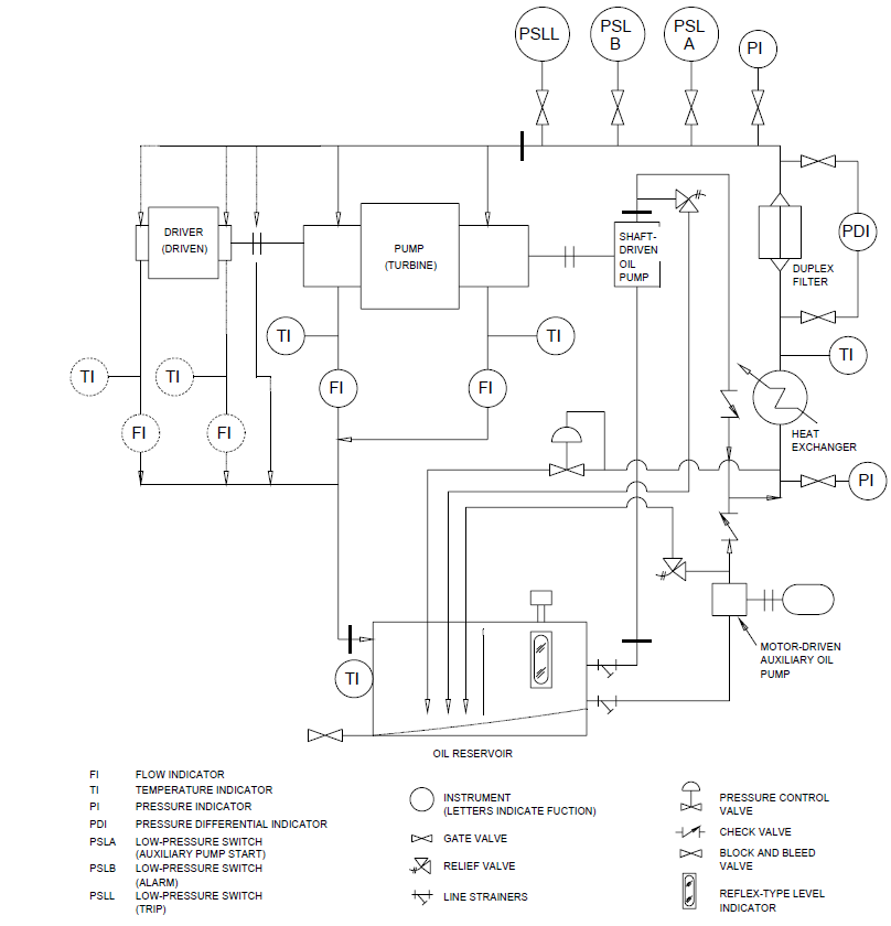
FIGURE 2
LUBE OIL SYSTEM VENDOR DRAWING AND DATA REQUIREMENTS
FOR
SITE
PURCHASE ORDER NO. DATE
REQUISITION NO. DATE
SERVICE INQUIRY NO. DATE
ITEM NO. PAGE OF BY
REVISION UNIT NO. REQUIRED
Proposal a
| DESCRIPTION | ||||||||
|---|---|---|---|---|---|---|---|---|
| 1. Certified dimensional outline drawing and list of connections. | ||||||||
| 2. Cross-sectional drawings and bills of materials. | ||||||||
| 3. Lube-oil schematic and bill of materials, including component sizing criteria. | ||||||||
| 4. Lube-oil arrangement drawing and list of connections. | ||||||||
| 5. Lube-oil component drawings and data. | ||||||||
| 6. Electrical and instrumentation schematics and bill of materials. | ||||||||
| 7. Electrical and instrumentation arrangement drawing and list of connections. | ||||||||
| 8. Console test agenda. | ||||||||
| 9. Weld procedures. | ||||||||
| 10. Certified hydrostatic test records. | ||||||||
| 11. Certified operational test logs. | ||||||||
| 12. As-built data sheets. | ||||||||
| 13. Operating and maintenance manuals. | ||||||||
| 14. Spare parts recommendation and price list. |
Bidder shall furnish copies of data for all items indicated by an
a Proposal drawings and data do not have to be certified or as built. Typical data shall be clearly identified as such.
b Purchaser will indicate in this column the desired time frame for submission of materials using the nomenclature given at the end of the form.
c Bidder shall complete these two columns to reflect his actual distribution schedule and include this form with his proposal.
© 2026 Inflection Point Engineering, LLC. All rights reserved. The content of this page — including calculation methods, reference data, written analysis, interactive tools, and source code — is the intellectual property of Inflection Point Engineering, LLC and is protected under applicable copyright, trademark, and trade secret laws. Unauthorized reproduction, redistribution, modification, or derivative use in whole or in part is prohibited without prior written consent.
Disclaimer. This material is provided for informational and educational purposes only and does not constitute professional engineering advice. Calculations, reference data, and methodologies are based on published standards and accepted engineering practice but are not a substitute for engineering judgment, site-specific analysis, or review by a licensed Professional Engineer. Inflection Point Engineering, LLC makes no warranties, express or implied, regarding the accuracy, completeness, or fitness for a particular purpose of any content presented here, and shall not be liable for any direct, indirect, incidental, or consequential damages arising from its use. Users assume all risk associated with applying this content to real-world design, operations, or decisions.
© 2026 Inflection Point Engineering, LLC. All rights reserved.