 Section 5 — Piping
Piping Stress Analysis and Supports
IPE Engineering Practice IPE-EP-5-1-3
Document number: IPE-EP-5-1-3 · Section: 5 — Piping
Inflection Point Engineering, LLC.
IPE-EP-5-1-3 Piping Stress Analysis and Supports
| 0 | |||||||
| Rev | Reason for Issue | Author | Date | Checker | Date | Approver / Issuing Authority |
Date |
| Unique Identifier: |
Not Applicable | IPE-EP-5-1-3 Piping Stress Analysis and Supports | Rev |
|---|---|---|---|
| RD Type: | Not Applicable | IPE-EP-5-1-3 Piping Stress Analysis and Supports | 0 |
Uncontrolled when printed or stored locally
| Revision Date | Revision Number | Approver | Revision |
|---|---|---|---|
| Name | Role | Type of Review | Date Reviewed |
|---|---|---|---|
Reference to corresponding documentation may be included in this template as context for the document the project is developing. References are for informational purposes only.
| Document Number | Document Name |
|---|---|
SCOPE
- This Practice covers the mandatory requirements for stress analysis of piping systems andthe design and location requirements for piping supports.
- Any deviation from this Practice must be approved by the procedure described in EP 1–1–3.
- An asterisk (*) indicates that a decision by the Owner’s Engineer or Owner, is required or that additional information is furnished by the Purchaser.
- A revision bar indicates all changes made to this Revision.
2.0 REFERENCES
The latest edition of the following standards and publications are referred to herein.
STANDARDS AND PUBLICATIONS
| IPE Engineering Practices | IPE Engineering Practices |
|---|---|
| EP 1–1–3 | Deviations to IPE Engineering Practices |
| EP 2–5–2 | Documentation Format Requirements |
| EP 4–1–1 | Design Criteria and Loads for Structures |
| EP 5–1–1 | General Piping Design |
| EP 5–1–2 | Piping Layout |
| EP 5–4–1 | Metal Expansion Joints |
| EP 5–5–3 | Piping Erection and Testing |
| EP 7–1–1 | Pressure Vessels |
| EP 10–2–1 | Material Requirements for Aggressive Environmental Services |
| EP 10–3–8 | Galvanized Coatings |
| EP 11–2–1 | Fireproofing |
| ASME Codes | ASME Codes |
| B31.1 | Power Piping |
| B31.3 | Process Piping Code |
| B31.4 | Pipeline Transportation Systems for Liquid Hydrocarbons and Other Liquids |
| Sec VIII | Pressure Vessels, Alternative Rules, Division 2 |
| API Publications | API Publications |
| Std 560 | Fired Heaters |
| Std 610 | Centrifugal Pumps for General Refinery Services |
| Std 611 | General Purpose Steam Turbines for Refinery Services |
| Std 612 | Special Purpose Steam Turbines for Refinery Services |
| Std 617 | Centrifugal Compressors for General Refinery Services |
| Std 618 | Reciprocating Compressors for General Refinery Services |
STANDARDS AND PUBLICATIONS (CONTINUED)
| API Publications (Continued) |
|---|
| Std 619 Rotary–Type Positive Displacement Compressors for General Refinery Services Std 620 Design and Construction of Large, Welded, Low–Pressure Storage Tanks Std 650 Welded Steel Tanks for Oil Storage Std 661 Air–Cooled Heat Exchangers for General Refinery Services Pub 941 Steels for Hydrogen Service at Elevated Temperatures and Pressures in Petroleum Refineries and Petrochemical Plants |
| MSS Publications |
| SP–58 Pipe Hangers and Supports–Materials, Design and Manufacture SP–69 Pipe Hangers and Supports–Selection and Application SP–77 Guidelines for Pipe Support Contractual Relationships SP–89 Pipe Hangers and Supports–Fabrication and Installation Practices |
| Publications |
| McKeehan, D.L., Peng, L–C, “Evaluation of Flanged Connections Due to Piping Load” Current Topics in Piping and Pipe Support Design, PVP–Vol. 53, The American Society of Mechanical Engineers, 1981, pages 61–69. Chadda, T.S., “Effect of Refractory Lining on the Stiffness of Steel Pipe”, Current Topics in Piping and Pipe Support Design, PVP–Vol. 53, The American Society of Mechanical Engineers, 1981 pages 79– 87. Becht, C., “Elastic Follow–up Evaluation for a Piping System with a Hot Wall Slide Valve”, Design and Analysis of Piping, Pressure Vessels, and Components–1988, PVP–Vol. 139, The American Society of Mechanical Engineers, 1988, pages 27–31. |
DEFINITIONS
- Abnormal Conditions - These are conditions, other than normal operating conditions, encountered in piping systems such as:
- A loss of cooling medium flow.
- Cessation of process flow while line heating facilities remain operative.
- Startup and shutdown requirements, including steamout and process upsets
- Causing temperature or pressure fluctuations.
- Fluid transient effects associated with a safety valve release event or hydraulic surge, see EP 4–1–1.
- Aggressive Environmental Service (AES) - Process services which result in material degradation such as cracking, scaling, blistering, and severe pitting and/or corrosion. Examples of such services are hydrogen service, wet hydrogen sulfide, cyanides, caustic, amine, and hydrofluoric acid. AES process fluid are defined in EP 10–2–1.
- Applicable ASME Piping Code - The ASME Piping Code which covers the piping systems being designed. The ASME Piping Code will either be ASME B31.1, ASME B31.3, or ASME B31.4. The scope and coverage of each of these codes is stipulated in the Scope section of the code in question.
- Average Minimum Winter Dry Bulb Temperature - The average of recorded coldest day average temperatures for the jobsite.
- Contractor - Company or business that agrees to furnish materials or perform specified services at a specified price and/or rate to the Owner.
- Hydrogen Rich Service - A service defined as a combination of hydrogen partial pressure and temperature at or below the curve for carbon steel per Figure 1 of API Publication 941, latest edition, and with a hydrogen partial pressure greater than 100 psia.
- Hydrogen Service - A service defined as a combination of hydrogen partial pressure and temperature above the curve for carbon steel per Figure 1 of API Publication 941, latest edition.
- Inspector - A Inflection Point Engineering, LLC appointed engineer or inspector.
- Manufacturer - The recipient of a direct or indirect purchase order for materials and/or equipment. In this context, a direct order is one issued to a manufacturer by a contractor or the Owner. An indirect order is one issued to a manufacturer by a vendor (recipient of a direct order) for materials, fabricated components, or subassemblies.
- Minimum Recorded Dry Bulb Temperature - The lowest recorded temperature for the jobsite.
- Owner - Inflection Point Engineering, LLC.
- Owner’s Engineer - A Inflection Point Engineering, LLC appointed engineer.
- Purchaser - The party placing a direct purchase order. The purchaser is the Owner’s designated representative.
PIPING STRESS ANALYSIS
- General Requirements
- Stress analysis of all piping systems shall be in accordance with the Applicable ASME Piping Code and the additional requirements of this Practice.
- (*)Piping expansion stresses and end reactions shall be calculated using the conditions that result in the largest differential temperature. The following temperatures shall be taken into consideration:
- Installation temperature, as established from meteorological data.
- Design metal temperature, including possible regeneration cycles, see paragraph 4.1.3.
- Abnormal conditions
- Steamout temperature - 300 F shall be used unless otherwise specified by the Owner’s Engineer. This thermal condition is not applicable if the line is designated on the P&lD as being exempt from steamout.
- Maximum and minimum operating metal temperatures caused by ambient conditions, for example, solar radiation.
- Heat–traced lines - assume a temperature of 25F less than steam temperature, for steam
traced lines, and 10 F less than the element temperature for electrically traced lines.
- The design metal temperature for each condition shall be the temperature of the contained fluid. The design metal temperature shall be determined as follows:
- For fluid temperatures less than or equal to 150 F, the design metal temperature shall be taken as the fluid temperature.
- For fluid temperatures above 150 F, the design metal temperature can be taken as the
fluid temperature. Alternatively, the design metal temperature can be determined by test or heat transfer calculation or, for uninsulated piping, taken as 5% less than the fluid temperature. Heat transfer calculations shall be based on the average maximum summer dry bulb temperature and a zero wind condition.
- The design temperature differential to be used in piping stress analyses shall be determined as shown in Table 1.
- (*)A detailed computer stress analysis of a piping system shall be used to determine structural adequacy when the piping system in question satisfies the criteria stipulated in Table 2. The procedure described in ASME B31.3 paragraph 319.4 shall not be used to determine requirements for a detailed piping stress analysis. It is emphasized that the intent of these criteria is to identify in principle those lines that should be considered for a detailed stress analysis. The final decision as to whether a computer stress analysis should be performed will depend on the complexity of the piping system, and is subject to the approval of the Owner.
Special Requirements
- Flexibility stresses in a venturi gate valve body shall be determined based on the minimum section modulus of the valve body(excluding ribs and bosses). The stress range calculated in this manner shall not exceed the allowable stress range for the valve material.
- Axial thrust loads in long, horizontal runs of pipe due to static friction resistance to thermal expansion at the support points shall not exceed the critical buckling load. If necessary, lateral guides shall be used to give stability to the line. In addition, no credit shall be taken for reduced thermal expansion movements or reduced flexibility stresses due to the elastic axial compression resulting from support point friction forces.
- Piping reactions at bolted flange connections shall be evaluated using the stress calculation method described in the paper by McKeehan and Peng, see Section 2.0 for thereference.
- The increased stiffness of piping systems caused by a refractory lining shall be included in the piping analysis. A method to evaluate the increased stiffness is described in the paper by Chadda, see Section 2.0 for the reference.
- (*)The effects of thermal bowing shall be included in the piping analysis. These effects typically occur in FCCU “hot–wall” standpipes that have poor catalyst circulation. In this service, the catalyst accumulates at the bottom of the pipe effectively insulating this surface from the process fluid. This insulating effect can result in a significant thermal gradient across the pipe cross section that results in additional thermal forces and moments on the piping system. The Owner will identify piping systems that may be subjected to thermal bowing.
- The effects of elastic follow–up shall be evaluated in piping systems. Elastic follow–up is a condition which results in the accumulation of unacceptable levels of inelastic strain in localized regions of a piping system as a result of the system’s flexibility characteristics (for example see ASME B31.3, paragraph 319.2.2). Examples illustrating the nature of elastic follow–up and a suitable evaluation procedure are described in the paper by Becht, see Section 2.0 for the reference.
- In the case of piping systems subjected to multiple thermal swings or cycles, the flexibility stress as defined in the Applicable ASME Piping Code shall be based on the maximum thermal moments should no reversal in bending occur, or on the maximum difference in thermal moments between any two thermal cycles should reverse bending occur. These effects typically occur in pump piping systems with a spare pump, cyclic reformer units, or other units that experience thermal swings or cycles.
- (*)Stress intensification factors used for non–standard piping components shall be subject tothe approval of the Owner.
- (*)The effects of soil restraint shall be included in the analysis of underground piping systems. The method used to model this restraint is subject to the approval of the Owner.
- Piping systems shall be designed for loads resulting from fluid transient effects. The transient loads to be considered are stipulated in EP 4–1–1.
- In double–wall or jacketed piping systems, axial stresses due to restrained thermal expansion shall be added to the thermal expansion stresses calculated in accordance with the Applicable ASME Piping Code prior to comparing the calculated thermal stress withcode allowable values.
- (*)Analysis procedures for non–metallic piping shall be in accordance with ASME B31.3, and shall be submitted to the Owner’s Engineer for approval prior to design of the piping system.
- For piping systems with non–linear, y–directional (gravity) supports, a stress analysis shall be completed for the sustained load plus thermal case. From these results, the activity of each y– directional non–linear support shall be determined. The entire stress analysis, including the sustained load plus thermal case, shall then be completed using only those supports found to be active.
Load Cases
- The load cases shown in Table 3 shall be examined for piping systems designated for stress analysis. Additional thermal load cases may be required to assess the temperature conditions stipulated in this Practice. In addition, when rotating equipment piping is connected with common headers, additional operating weight plus thermal load cases are required to assess the variation in pipe temperature which results from combinations of operating and non– operating (for example, spare) equipment.
- Wind and earthquake loads acting on piping shall be determined in accordance with
EP 4–1–1. The effects of equipment flexibility, differential support movements, and wind and earthquake loads acting on the equipment shall be considered in the analysis.
- The piping system shall be designed to satisfy the longitudinal stress limits for sustained loads in all operating conditions. Supports that are inactive because the pipe has lifted off them in the operating condition shall be considered inactive in the longitudinal stress evaluation for sustained loads.
Computer Programs
- (*)The computer program used for piping stress analysis by a contractor is subject to the approval of the Owner. In order to determine acceptability, the Owner reserves the right to request the analysis of a benchmark piping system which contains many typical piping system geometries, piping components, equipment connections, and supports.
- As a minimum, the computer program used for stress analysis shall have thefollowing capabilities:
- Elements to model the piping system shall include: straight pipe, smooth bend, or elbow, closely spaced and widely spaced miter bends, flanges and valves (or rigid elements), structural shapes, bellows or flexible members, vessel connections, and tank connections.
- Elements to model support types including anchors, orthogonal skewed restraint, single- acting restraint gap, and frictional restraints.
- Load case analysis capabilities including the effects of weight, pressure, thermal expansion, support displacement, static earthquake, wind, and support friction.
- A spring hanger design feature.
- Minimum output report including:
- The system description including geometry,material properties and weights of piping components.
- Member force and displacement results at node points.
- Support displacements and reactions.
- ASME B31 .3, B31 .1, or B31 .4 Code Compliance report.
- Rotating equipment compliance reports.
- Spring hanger summary.
- Computer generated graphics to verify the input data and results of an analysis.
Piping Stress Analysis Documentation
- (*)When a detailed computer stress analysis of a piping system is required per the criteria established in this Practice, a Stress Analysis Report containing the information specified in the following paragraphs shall be submitted to the Owner for review and approval.
- A stress isometric drawing shall include, as a minimum, the following information:
- A global coordinate system with the positive linear and angular direction indicated for the x, y, and z reference axes. The plant North direction shall be shown with respect to this global reference frame.
- A reference plant elevation, and if applicable, horizontal dimensions with respect to a reference point on a building or vessel shall also be included.
- Key node points used in the analysis, labeled and located. Dimensions between node points shall be resolved into components parallel to each of the three global axes.
- Locations, functions, and lines of action of all supports. All spring hanger spring stiffnesses, hot and cold load settings, and design travel shall be included. Additionally, the spring hanger model number and manufacturer name shall be provided.
- Other piping design parameters used in the analysis, such as pipe sizes, thicknesses and piping materials, insulation and refractory densities, thicknesses and manufacturer designation, and valve and flange weights and locations.
- The general arrangement of all equipment to which the piping is attached, including, but not limited to, pressure vessels, tankage, and rotating equipment.
- Support displacements used in the analysis, such as foundation settlement.
- Information on special supports, such as snubbers, sway braces, or vibration dampeners.
- In addition, the following supplemental information shall be provided:
- Equipment drawings for all vessels, exchangers, fired heaters, rotating equipment, tankage, etc., to which the piping is attached. These drawings shall include, as a minimum, basic overall dimensions, material, nozzle locations and details where piping is attached, and equipment support locations.
- Pressures, temperatures, and content specific gravity for all load cases. Data on any pipe sections with high temperature gradients, thermal bowing, or transients shall be included as well.
- Expansion joint stiffness and movements (axial, transverse, and rotational), bellows’ inside and outside diameters, thickness, length, pitch, number of plies and convolutions, and overall expansion joint assembly weight.
- Any vibration data used in the analysis.
- A tabulation of nozzle loads on rotating or other load sensitive equipment showing the computed and allowable values.
- (*)Program output showing all analysis results for the specified load cases (see Section 4.3) shall be provided on hardcopy output. Alternatively, requests to submit output on magnetic media (for example: PC diskettes or CD-ROM) shall be submitted to the Owner for approval.
- Documentation requirements shall be in accordance with Table 4.
Piping Layout, Flexibility and Expansion Joints
- Where the layout of a piping system does not inherently provide adequate flexibility, the flexibility shall be provided by additional pipe bends, loops, or offsets.
- (*)The use of cold spring to reduce piping reactions at equipment connections shall only be permitted with written approval by the Owner’s Engineer.
- (*)The use of any convoluted or proprietary expansion joints for all fluid services except Category D Fluid Service as defined in ASME B31.3, shall not be considered without prior written approval from the Owner. If expansion joints are approved, they shall conform to the following requirements:
- Bellows expansion joints, where approved, shall be equipped with adequate pressure thrust restraints. Preferably, expansion joints should be of the hinge, gimbal, or universal type that have pressure thrust restraint inherently designed. The piping system shall be suitably anchored and guided to permit required hydrostatic or pneumatic testing without removing or blanking the joints.
- The expansion joint design shall meet the requirements of EP 5–4–1.
- The installation arrangement of any expansion joint shall be subject to approval by the Owner and shall be reviewed by the expansion joint manufacturer. This approval and review shall include service conditions, anchors, guides, supports and piping configuration, and all necessary calculations.
- The piping flexibility analysis shall include models of all expansion joints using the manufacturer’s flexibility constants and any pressure thrust loads on the piping (e.g., pantographic expansion joints). In such cases, the pressure thrust acting on the structure shall be determined and noted on the structural drawings. A nameplate shall be attached to the structure indicating that pressure thrust is being supported by the structure, see
EP 5–5–3.
- (*)The use of Dresser couplings or expansion joints in the suction or discharge lines of pumps in cooling water service is acceptable. They shall be located on the pump side of the pump suction or discharge block valve, as appropriate. All pressure thrust loads shall be absorbed by anchors or tie rods and not by the coupling or expansion joint. The type of coupling and piping system design shall be reviewed with the Owner.
- (*)As an alternative to bellows expansion joints, ball joints may be considered for some applications. However, their use depends on location and operating conditions and requires prior approval by the Owner.
- Piping containing Grayloc connectors shall possess sufficient inherent flexibility to allow installation of the seal rings without damage to them or to the seating surfaces on the hubs.
Requirements for Pressure Vessels and Heat Exchangers
- Displacements resulting from thermal expansion of pressure vessels and heat exchangersshall be included in the piping analysis.
- (*)Nozzle loads for pressure vessels and heat exchangers shall be checked for compliance by the piping contractor. The localized vessel and nozzle stresses resulting from these nozzle loads shall be evaluated according to the stress analysis and fatigue evaluation procedures described in EP 7–1–1. The methods used to compute these localized stresses are subject to the approval of the Owner.
Requirements for Rotating Equipment
- Forces and moments imposed on the nozzles of rotating equipment with piping connections shall be in accordance with the standards shown in Table 5. The piping shall be installed to meet allowable rotating equipment flange misalignment criteria per EP 5–5–3.
- Centrifugal and axial compressors, steam turbines, and centrifugal pumps with suction or discharge nozzles greater than NPS 2 shall be evaluated using the load cases and evaluation criteria in Table 6.
- When using Table 6, weight loads include the weight of piping, insulation or refractory, heat tracing, and the process fluid, and internal pressure. Thermal Expansion load considerations shall be governed by the following:
- Piping expansion or contraction.
- The expected thermal movements at equipment flanges due to casing expansion or contraction shall be obtained from the equipment vendors.
- For the case of “process flow off/heat tracing on,” process piping metal temperature shall be considered equal to the heat tracing design temperature unless the average metal temperature is determined by heat transfer calculations.
- Consideration shall be given to installations with spare pumps. If no warm–up facilities are required, interconnecting piping metal temperature shall be considered to be at minimum ambient temperatures. If warm–up facilities are required, the metal temperature shall be taken as the average of the design and ambient temperatures.
- The variation of spring force with deflection shall be included in the analyses.
- The following assumptions regarding temperature shall be made for spare pumps connected in parallel with operating pumps when they are not in operation unless heat transfer calculations or actual field measurements are provided to justify alternative values.
- When there are no warm–up facilities, the piping to the spare pump where there is no flow shall be considered to be at ambient temperature.
- When there are warm–up facilities and the piping is insulated, the piping shall be considered to have a temperature equal to the design metal temperature and the ambient temperature.
- The flexibility of pipe restraints near rotating equipment, that are not designed in accordance with Section 5.0 of this Practice shall be considered in the piping stress analysis.
- The effects of friction shall be considered. When it is apparent that frictional effects will significantly increase nozzle loadings, the piping stress analysis shall include frictional effects. No credit shall be taken for frictional effects when they result in reduced nozzle loadings.
- The use of cold spring to achieve compliance with paragraphs nozzle loads given in Tables 5 and 6 of this Practice is prohibited.
- (*)Calculations necessary to assure compliance with nozzle loads given in Tables 5 and 6 of this Practice shall be submitted for approval to the Owner.
- (*)The proposed method of evaluating the effects of compressor recycle operation or discharge from pressure relief devices shall be reviewed with the Owner.
- (*)Loads on non–operating rotating equipment (including spare pumps, etc.) may generally be 50% higher than the maximum permissible loads stipulated for the operating case. However, approval from the rotating equipment manufacturer shall be obtained prior to acceptance of these higher allowable loads.
Requirements for Fired Heaters
- Piping reactions on fired heater coil connections purchased to the APl 560 shall be evaluated in accordance with the criteria described in this standard.
- Displacements at fired heater coil connections resulting from thermal expansion shall be included in the piping analysis.
Requirements for Tankage
- Piping loads on low–type tank nozzles on atmospheric storage tanks designed per APl 650 shall be evaluated in accordance with the criteria described in Appendix P of APl 650.
- (*)Piping loads on atmospheric storage tank (APl 650) flush–type nozzles, and on nozzles of low pressure storage tanks (APl 620) shall be checked for compliance by the Contractor. The localized tank and nozzle stress resulting from the nozzle loads shall be evaluated by the stress analysis and fatigue procedures described in Appendices 4 and 5 of the ASME Code, Section VIII, Division 2. The method used to compute these localized stresses is subject to the approval of the Owner.
- Displacements resulting from rotation of the tank shell due to hydrostatic head, thermal expansion (for hot product tanks), and predicted foundation settlement shall be included in the piping analysis.
- Requirements for Air-Cooled Heat Exchangers
Piping reactions on air-cooled heat exchanger nozzles and heaters shall be in accordance with API 661.
SUPPORTS
- General
- (*)Supports shall be designed to carry the loads that exist during all operating load cases at the stated design conditions. In addition, supports shall be suitable for carrying the weight of the piping when filled with water during hydrostatic pressure testing, except where:
- Pneumatic testing has been approved by the Owner.
- Temporary supports, such as those that may be required for some spring supported piping, have been approved by the Owner. Specific locations and details for these supports shall be shown on layout drawings.
- (*)The coefficients of static friction used to determine forces at sliding surfaces shall be in accordance with EP 4–1–1. The designs of pipe supports, anchors, and restraints employing PTFE or other low friction materials for bearing surfaces shall be reviewed by the Owner’s Engineer.
Pipe Supports
- (*)All supports and parts shall conform to the latest requirements of ASME B31.3, or ASME B31.1 as applicable, and MSS SP–58 and MSS SP–69 as supplemented or modified by the requirements of this Practice. Any exception to these codes and standards requires approval of the Owner’s Engineer.
- (*)The guidelines contained in MSS SP–77 for defining areas of responsibility for pipe hanger contractors, pipe fabricators and/or erectors, and the Purchaser shall be followed. All deviations from these guidelines shall be documented and submitted for review to the Owner.
5.2.3 MSS SP–58 support types 1, 2, 5, 6, 7, 9, 10, 11, 12, 15, 16, 19, 20, 23, 28, 29, 30, 41, 43, and
49 shall not be used.
- (*)Each support for a line should carry approximately the same portion of the line weight. When it is anticipated that a line will deflect vertically as a result of thermal expansion or contraction, and thereby unload some supports and overload others (including equipment nozzles), spring hangers should be provided. If the deflection is of the order of 1.0 inch or less, variable spring hangers should normally be used. For deflections greater than 1.0 inch constant–support spring hangers should be considered. Where deflection exceeds 2.0 inches or the load variation exceeds the values stipulated in paragraph 5.7.6, constant–support spring hangers shall be provided. The use of counterweight type supports in lieu of constant support spring hangers is subject to the approval of the Owner’s Engineer.
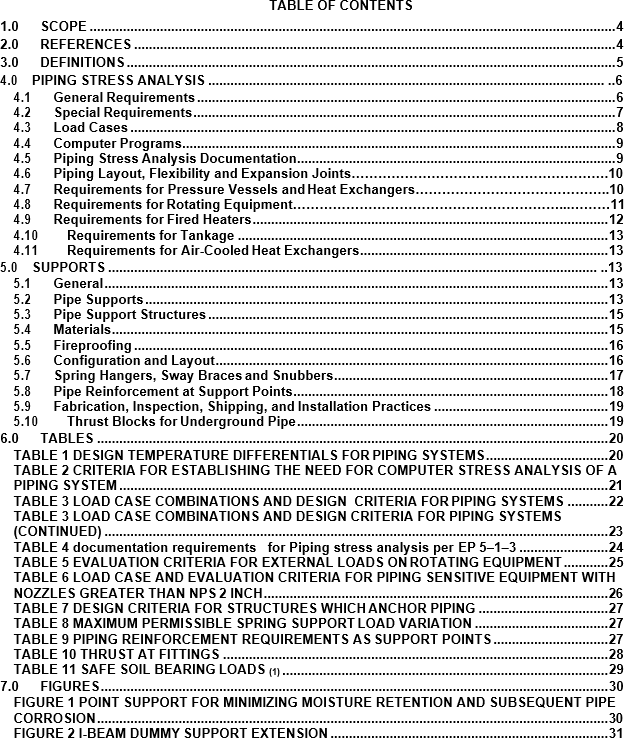
- (*)Unless otherwise specified by the Owner’s Engineer, support configurations for piping shall be as follows. In both cases, the support beam shall be equipped with a rod welded only to the support beam (not the pipe) to provide point support to mitigate the effects of crevice corrosion.
- The following lines shall be supported with steel support shoes attached to the pipe which rests on the support beam regardless of the line temperature:
- All insulated pipe.
- Uninsulated pipe NPS 2 and greater.
- For uninsulated pipe less than NPS 2, the line shall be installed directly on thesupport beam.
- Heat traced lines containing fluids which will congeal during non-flowing conditions (e.g., tars, chemicals) shall be supported by shoes or similar devices which will permit continuous insulation at the support beams.
- Cold service insulated piping shall be supported by rigid bands, saddles, or similar devices matching the outside diameter of the insulation to provide continuous insulation at the support beam. Insulation at supports shall be of the bearing type suitable to sustain the pipe load.
- The sizes of parts for pipe supporting elements shall be in accordance with the following:
- Hanger rods shall not be less than 3/8 inch in diameter.
- Straps shall not be less than 1/8 inch thick by 3/4 inch wide for NPS 1 smaller, or less than 1/4 inch thick by 1 inch wide for supporting NPS 1–1/2 and larger.
- Bolted clamps used in connection with rod hangers shall have a minimum thickness of 3/16 inch for NPS 1 and smaller and a minimum thickness of 1/4 inch for NPS 1–1/2 and larger. Bolts used with these clamps shall have a diameter of 3/8 inch or larger.
- In corrosive environments (for example, marine applications), built–up steel supports shall be fabricated of 3/8 inch plate as a minimum. Rolled shapes less than 3/8 inch thick (web, flange, or plate) shall not be used unless they are hot–dip galvanized.
- The use of clamp–type U–bolt supports for vertical lines is limited to cool -20 F to 300 F lines, NPS 2 and smaller. If such supports are used for vertical lines, a lug (of the same material as the pipe) shall be welded to the pipe to prevent slippage. U–bolts shall not be used as anchors. When U–bolts are used as guides, they shall be nutted to provide a minimum of clearance, 1/16 inch, between pipe and U–bolt. U–bolt supports for horizontal piping are limited to NPS 1 and smaller.
- Guides and stops where gaps are required for expansion stress or equipment load limits shall be identified on the piping stress isometric and piping layout drawings as guides with critical gaps.
- Guides and stops in piping near load sensitive equipment, where movements in the direction of the restraint would result in equipment overload, shall be designed with and identified on the piping isometric and piping layout drawings as requiring zero gap.
Pipe Support Structures
- Steel and reinforced concrete pipe support structures shall be designed in accordance with EP 4–1–1 and the additional requirements of this Practice.
- Piping anchors and restraints shall be designed for the forces developed under normal or abnormal conditions, whichever governs. Anchors shall be sufficiently rigid to transmit all load effects into their supports structures and foundations. The design of structures anchoring more than one line shall accommodate the more stringent combination of the forces due to abnormal conditions shown in Table 7.
- Pipe support structures on marine piers shall be designed for the static friction thrust generated by 25% of the piping, rounded up the next larger whole number of lines, undergoing thermal movement at any one time. The most severe combination of lines moving in the same direction shall be included in the 25%.
- Structures on marine piers anchoring four or fewer lines shall be designed for the forces developed due to static friction and abnormal temperature based on the line percentage indicated above. Structures anchoring more than four lines shall be designed for the more severe condition of the subparagraphs below. The number of lines considered in eachcase shall be rounded up to the next larger whole number.
- Reactions, based on frictionless analysis, due to thermal movement of all piping, considering the more severe of either the design metal temperature or abnormal temperature. However, in no case shall more than 35% of the lines be considered at abnormal temperature at any one time.
- Static friction reactions generated by 25% of the piping undergoing thermal movement at any one time, plus friction less thermal movement reactions of the remaining piping at design metal temperature. The more severe combination of the lines moving in the same direction shall be included in the 25% developing friction. This friction reaction shall be based on the cumulative friction effort at all supports located in an essentially longitudinal direction from the anchor up to the first significant line direction change. The friction reaction from a maximum of two supports beyond the line direction change shall also be included.
- Materials
- (*)Unless otherwise approved bythe Owner, support materials shall conform to MSS SP–58 and the following requirements.
- P–1 support materials may be welded to P–1, P–4 and P–5 pipe materials fordesign temperatures less than or equal to 800F.
- Support materials welded to the pipe with the same P number as the pipe material shall be used at temperatures up to 1000 F. However, an assessment of stress levels resulting from thermal gradients must be completed when the support is designed. The analysis method and compliance criteria used to determine the structural adequacy of the proposed support system shall be subject to the approval of the Owner’s Engineer.
- For other materials and design conditions, pipe clamps shall be used and shall be fabricated from the same material as the pipe to which they are attached, unless otherwise approved by the Owner’s Engineer. When dissimilar material pipe clamps are approved (for example, steel clamps and cupro–nickel pipe) and the environment makes a galvanic cell possible, insulating material is required between the clamp and the pipe.
- The following materials shall not be used for pipe supports:
- Cast Iron
- Ductile Cast Iron
- Malleable Cast Iron
- Wood
- Insulation shoes, anchors, guides, support clips, miscellaneous brackets, and any other welded attachments shall be welded on piping designated for heat–treatment before final treatment. The Manufacturer shall ensure that these welded attachments are not damaged during heat treatment.
- Galvanized pipe supports shall not be used with stainless steel pipe.
Fireproofing
- Fireproofing of supports shall be in accordance with EP 11–2–1.
- (*)Where piping containing flammable materials is hung by rods or spring type supports from a fireproofed pipe support cross beam, a fireproofed “Catch beam” shall be installed beneath the piping. The provision and location of emergency supports or “catch beams” shall be subject to the approval of the Owner’s Engineer.
Configuration and Layout
- Supports shall be arranged so that special valves or other equipment requiring periodic maintenance, such as safety or control valves, may be readily removed for servicing without affecting permanent supports and without the use of temporary supports.
- The minimum vertical clearances between finished grade (paving of top of floor plate) and the bottom of the piping, insulation or support, whichever controls, shall be in accordance with EP 5–1–2.
- To minimize moisture retention and subsequent pipe corrosion, all support members shall be equipped with a steel bar or angle welded to the support beam (not the pipe) to provide point support of the pipe and to provide a minimum of 1/2–inch clearance from the support members, see Figure 1. Half–pipe cradle supports or sleeve anchors, fitting concentrically around the pipe, shall not be employed.
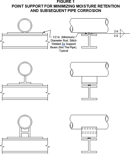
- Dummy extensions from elbows may be used to reach beams or brackets beyond the turn. Extended dead–end tees shall not be substituted for these elbows. Dummy supports shall be attached to the pipe with a continuous full–penetration weld. Dummy extensions may be either pipe or open structural shapes (e.g. I–Beam, see Figure 2 ).
- (*)Dead–end extensions of piping shall not be used in lieu of dummy pipe supports, or equivalent structural members, to span the distance from piping runs to the nearest support structure. Dummy pipe supports, where used, shall be provided with a low point drain hole (1/2 inch minimum diameter). For horizontal installations, the drain hole shall be located near the point of attachment to the piping component. Where stagnant or confined areas of piping are unavoidable due to piping layout requirements, the location of all such piping components shall be documented to the Owner for corrosion monitoring.
- (*)The maximum spacing for pipe supports in process units shall not exceed 30 feet unless approved by Owner. The maximum deflection during operation shall not exceed the smaller of 3/4–inch or one–half the inside diameter of the pipe.
- When the distance between supports is excessive for small lines, they may be supported from adjacent large lines if an engineering analysis shows it will not be detrimental to either line. For example, small lines shall not be supported from large lines subject to extreme thermal expansion movements. If support from large lines is found to be unacceptable, additional pipe supports shall be provided. Consideration shall be given to the use of lightweight trusses to provide support to a group of small lines.
- Spacing for overhead pipeway supports shall be based on the piping size mix to secure maximum economy. Where support spacing exceeds allowable spans for small lines (NPS 2 and smaller), the lines shall be grouped (when feasible) to simplify supporting methods. To eliminate an intermediate support for a small line, it may be economical to increase line size.
- (*)Davits or other means shall be provided for handling all blind flanges, valves, fittings and other equipment that weigh in excess of 100 lb and are removed from the line on an average of at least once a month. Requirements for davits will be specified by the Owner.
- Where horizontal piping movements are such that the hanger rod angularity from the vertical is greater than 4 degrees from the cold to hot position of the pipe, the hanger pipe and structural attachments shall be offset in such a manner that the rod is vertical in the hot position.
- An anchor shall be provided at the battery limit when piping extends beyond it. The necessary flexibility shall be provided on both sides of the battery limit.
- Piping supports shall not be structurally supported from pressure vessel platforms unless the platform is specifically designed to support these loads.
Spring Hangers, Sway Braces and Snubbers
- Variable or constant effort base spring supports shall not be used at points of horizontal line movements in excess of 0.25 inches unless the base assembly has been designed for the friction forces.
- (*)Substitution of counterweights for spring hangers requires prior approval of the Owner. When used, the counterweights shall be provided with stops to limit travel.
- Pipe hangers shall be capable of supporting the pipe in all conditions of operation. They shall allow free expansion and contraction of the piping, and prevent excessive stress resulting from transferred weight being induced into the pipe or connected equipment.
- The allowable travel for constant support hangers shall be equal to design travel plus a minimum of 20%. In no case shall the difference between the design and allowable travel be less than 1 inch. The allowable travel for variable spring supports hanger shall be equal to the design travel plus a minimum of 10%.
- The variation in the support force at variable spring locations shall be per Table 8.
- Cold and hot load settings shall not vary by more than plus or minus 1/8 inch from data sheet specified values.
- Spring type supports and restraints shall be provided with upper and lower travel stops that are to be adjusted to the cold load setting. These shall be marked and instructions for their removal and reengagement shall be supplied with the assemblies. The lower travel stop shall be designed for the full hydrostatic test loads as noted in the data sheet. Travel stops shall be designed to prevent excessive spring deflection.
- Pouches or metallic containers connected to the spring housing with cables or chains attached to the travel stops shall be provided to store the travel stops for future re–use.
- All spring supports shall be equipped with internal guides when the specified movement exceeds 1/4 inch.
- All spring hangers shall be provided with a label to indicate the proper position of the spring with respect to the hot and cold positions of the piping. The label shall be made of a corrosion resistant metal and shall be permanently fastened to the spring housing. Painting of spring support calibration plates is strictly prohibited. In addition, the label shall be stamped with the following information:
- Spring Scale: Load vs. Deflection
- Spring Rate - Actual
- Engineer’s Assembly Tag Number
- Spring Size and Type
- Hot (Operating) and Cold (Installed)
- Load Settings
- Minimum Design Operating Temperature
- Serial Number
- Date of Manufacture
- Vendor Name and Address
- The load indicator for the spring type supports and restraints shall be provided as an integral part of the piston plate and shall be designed to move along the spring scale without binding.
- Lifting lugs shall be provided for assemblies weighing more than 100 pounds.
- Spring hangers shall be designated to be corrosion resistant; hence, they shall be hot–dip galvanized, per EP 10-3-8.
Pipe Reinforcement at Support Points
- Pipe reinforcing at locations of point or line support for horizontal pipe runs shall be per Table 9.
- Reinforcement pads or saddles shall be fabricated from a material with the same P–number as the pipe to which they are attached.
Fabrication, Inspection, Shipping, and Installation Practices
- Procedures for detailing, fabrication, inspection, packaging and shipping, and installation of pipe supports shall be in accordance with MSS SP–89, and the additional requirements of this Practice.
- (*)Supports for piping NPS 3 and larger, and all spring support assemblies, shall be completely engineered. All engineering pipe supports are subject to the approval of the Owner.
- Engineered spring hanger assemblies shall be detailed on a separate drawing. Each drawing shall include an exact bill of material for the component parts making up each assembly.
- The location of each spring hanger shall be identified on the piping stressisometric and piping layout drawings.
- Each engineered hanger assembly will be individually packaged and tagged as far as practical, ready for installation.
- Test requirements for hangers will be specified by the Owner’s Engineer.
- Support material for piping NPS 2 and smaller shall be shipped as loose material, identified by piping system only. Hanger sketches showing typical support arrangements, accompanied by a copy of the piping drawing marked with approximate hanger locations, will be supplied by the Contractor.
- The pipe support Manufacturer shall maintain an inspection program to ensure that all aspects of fabrication including material procurement and fabrication procedures fully comply with all specified requirements. The suggested inspection program outlined in MSS SP–89 is mandatory.
- (*)Special packing and shipping requirements, supplemental to those of MSS SP–89, will be specified by the Owner’s Engineer.
- Installation requirements for piping supports are covered in EP 5–5–3.
Thrust Blocks for Underground Pipe
- This section contains mandatory requirements governing the sizing and installationof thrust blocks for underground pressure piping employing non–welded girth or non–flanged joints.
- For bell and spigot cast iron piping with poured lead joints, credit may be taken for strength of the joint when sizing thrust blocks.
- Thrust blocks shall be cast–in–place concrete.
- The thrust blocks shall be placed in either undisturbed soil, or if the soil has been disturbed or is in an unconsolidated state, the soil shall be densely compacted for a distance of at least five (5) pipe diameters from the face of the block and to a depth of three (3) pipe diameters underneath the block over an area twice the size of the block.
- Thrust blocks shall be provided at all directions of the pipe exceeding ten (10) degrees from straight alignment, at all branch connections, and at the end of pipe runs
- Thrust blocks shall be sized on the basis of hydrostatic test pressure in accordance with the information given in Table 10 and Table 11. Irrespective of the calculated size, theminimum size block shall have a one (1) square foot face for transmitting the thrust load to the soil.
6.0 TABLES
TABLE 1
DESIGN TEMPERATURE DIFFERENTIALS FOR PIPING SYSTEMS
| DESIGN METAL TEMPERATURE | DESIGN TEMPERATURE DIFFERENTIAL(2)(3) |
|---|---|
| Above 120 F (1) | Metal temperature minus average minimum winter dry bulb temperature |
| Below 120F, but above average minimum winter dry bulb temperature (1) |
120 F minus average minimum winter dry bulb temperature (1) |
| Below average minimum winter dry bulb temperature. | 120 F minus metal temperature (1) |
NOTES:
- The 120F temperature is considered the maximum metal temperature resulting from solar radiation with no flow in the line.
- Under certain conditions of dual service, the fluid temperature range may be both above 120 F and below average minimum winter dry bulb temperature.
- (*)For evaluation of nozzle loads on rotating equipment, the temperature differential may be based on the design metal temperature and an installed temperature (e.g. 70oF) if approved by the Owner’s Engineer.
TABLE 2
CRITERIA FOR ESTABLISHING THE NEED FOR COMPUTER STRESS ANALYSIS OF A PIPING SYSTEM
| Description | Pipe Size (NPS) | Design Temperature Differential (1) (oF) |
|---|---|---|
| Piping Connected To Rotating Equipment | ≥2 | All Temperatures |
| Piping Connected To Air–Cooled Heat Exchangers |
≥4 | All Temperatures |
| Piping Connected To Tankage If Shell Settlement Is A Concern(2) |
≥2 | All Temperatures |
| Underground Piping | w≥4 | ≥40 |
| ≥8 | ≥30 | |
| General Piping | ≥2 | ≥500 |
| ≥4 | ≥400 | |
| ≥8 | ≥300 | |
| ≥12 | ≥200 | |
| ≥20 | All Temperatures | |
| Double–Wall Piping | ≥2 | Same temperature limits as general piping, and when the temperature difference between the inner and outer pipes exceeds 40oF |
NOTES:
- See Paragraph 4.1.3.
- Shell settlement criteria will be specified by the Owner’s Engineer.
TABLE 3
LOAD CASE COMBINATIONS AND DESIGN CRITERIA FOR PIPING SYSTEMS
| Load Case | Design Loads and Forces | Evaluation Criteria |
|---|---|---|
| Testing or Flushing Equipment | Weight of all piping components. Pressure and fluid weight (water) for testing of flushing of piping. Wind load for a wind speed of 35 mph. |
Minimum specified yield stress. |
| Operating Weight | Weight of all piping components, refractory, insulation. Weight loads resulting from lift–off of pipe sections from any support shall be included. Pressure and fluid weight of product. Ice and snow loads, if applicable. All other sustained loads supported by the piping. |
Sustained stress limits per the Applicable ASME Piping Code evaluated at the design temperature. |
| Thermal | Thermal loads resulting from design temperatures and restraints. Loads due to temperature gradients, for example. Thermal loads resulting from differences in expansion coefficients. Effects of support displacement including thermal expansion or contraction and foundation settlement, if applicable. |
Allowable displacement stress range per the Applicable ASME Piping Code evaluated at the design temperature. |
TABLE 3
LOAD CASE COMBINATIONS AND DESIGN CRITERIA FOR PIPING SYSTEMS (CONTINUED)
| Load Case | Design Loads and Forces | Evaluation Criteria |
|---|---|---|
| Operating Weight Plus Thermal | Loads from the Operating Weight and Thermal Cases. Loads due to support friction. |
Check equipment loads per paragraphs 4.7, 4.8, 4.9. and 4.10 . |
| Normal - Operation Weight Plus Occasional | Loads from the Operating Weight Case. Full wind or earthquake loads, whichever results in the highest piping stresses. Loads due to support friction. |
In accordance with the Applicable ASME Piping Code evaluated at the design temperature.(1) |
| Abnormal Conditions Plus Reduced Occasional, see paragraph 3.1 (2) | Weight of all piping components, refractory, insulation. Weight loads resulting from lift-off of pipe sections from any support shall be included. Operating pressure and fluid weight during abnormal conditions. Thermal loads resulting from abnormal conditions. Fluid transient loads from abnormal conditions. Loads due to support friction. Wind load for a wind speed of 35 mph. |
In accordance with the Applicable ASME Piping Code evaluated at the abnormal temperature with consideration given to Code allowances from Pressure and Temperature Variations. |
| Empty Weight Plus Occasional (3) |
Weight of all piping components, refractory, insulation. Full wind. |
In accordance with the Applicable ASME Piping Code evaluated at ambient temperature. |
NOTES:
- Except where prohibited by the Applicable ASME Piping Code (e.g. When the basic allowable stress exceeds 2/3 of the yield stress at temperature).
- Only applicable abnormal conditions shall be analyzed. In the case of steam-out, if normal conditions are more severe, the steam-out case is not required.
- (*)When required by the Owner’s Engineer. May be applicable at sites where units are shut-down and drained in anticipation of severe wind event.
TABLE 4 DOCUMENTATION REQUIREMENTS
FOR PIPING STRESS ANALYSIS PER EP 5–1–3
| Item | Description | Format | As–Built |
|---|---|---|---|
| 1 | Stress Isometric drawing | See EP 2–5–2 | Yes |
| 2 | Supplemental information | See EP 2–5–2 | Yes |
| 3 | Output from the computer program used for stress analysis | See EP 2–5–2 | Yes |
TABLE 5
EVALUATION CRITERIA FOR EXTERNAL LOADS ON ROTATING EQUIPMENT
| Equipment Type | Evaluation Criteria |
|---|---|
| Centrifugal Pumps | APl 610 (1) |
| Reciprocating Pumps | Manufacturer’s Recommended Values |
| Gas Turbines | Manufacturer’s Recommended Values |
| Steam Turbines | APl 611 or APl 612 as applicable (1) |
| Centrifugal Compressor | APl 617 (1) |
| Rotary Positive Displacement Compressor | APl 619 (1) |
| Reciprocating Compressor | Manufacturer’s Recommended Values |
NOTES:
(1) Allowable loads shall be per the referenced APl standards unless the Manufacturer’s recommended values are explicitly cited in the purchase specifications for the equipment.
TABLE 6
LOAD CASE AND EVALUATION CRITERIA FOR PIPING SENSITIVE EQUIPMENT WITH NOZZLES GREATER THAN NPS 2 INCH
| EQUIPMENT | LOAD CASES (1) |
CONDITION OR CONFIGURATION | EVALUATION CRITERIA | EVALUATION CRITERIA |
|---|---|---|---|---|
| Centrifugal and Axial Compressors, Steam Turbines | Flange alignment | Piping not connected to equipment flange Spring supports active Piping at cold condition |
Piping installed to meet allowable flange mis- alignment criteria per EP 5–5–3 | Piping installed to meet allowable flange mis- alignment criteria per EP 5–5–3 |
| Centrifugal and Axial Compressors, Steam Turbines | Weight and thermal expansion | Piping connected to equipment Spring supports active All normal and abnormal operating conditions |
Per paragraph 4.8.1 and Table 5 | Per paragraph 4.8.1 and Table 5 |
| Centrifugal and Axial Compressors, Steam Turbines | Weight and thermal expansion | Piping connected to equipment Spring supports active All normal and abnormal operating conditions |
||
| Centrifugal and Axial Compressors, Steam Turbines | Weight, thermal expansion, and friction | |||
| Centrifugal Pumps | Weight and thermal expansion | Piping connected to equipment Spring supports active All normal and abnormal operating conditions |
Per paragraph 4.8.1 and Table 5 | Per paragraph 4.8.1 and Table 5 |
| Centrifugal Pumps | Weight and thermal expansion | Piping connected to equipment Spring supports active All normal and abnormal operating conditions |
||
| Centrifugal Pumps | Weight, thermal expansion, and friction |
NOTES:
(1) See paragraphs 4.8.3 and 4.8.4.
TABLE 7
DESIGN CRITERIA FOR STRUCTURES WHICH ANCHOR PIPING
| Total No. of Lines at an Anchor Structure That Could Have Abnormal Conditions | Percent of Lines Under Abnormal Conditions to Be Used in Design (1) |
|---|---|
| 1 2–4 Over 4 |
100% 50% 25% |
NOTE:
- Use next larger whole number of lines indicated. Generally select largest lines, providing thrust loads are in the same direction.
TABLE 8
MAXIMUM PERMISSIBLE SPRING SUPPORT LOAD VARIATION
| SERVICE | LOAD VARIATION (%) |
|---|---|
| Severe Cyclic Conditions per ASME B31 .3 | 6 |
| Piping Connected to Rotating Equipment | 10 |
| Piping with a Design Temperature > 500 F or a Pressure Rating > Class 300 |
15 |
| All Other Services | 25 |
TABLE 9
PIPING REINFORCEMENT REQUIREMENTS AS SUPPORT POINTS
| PIPE DIAMETER D (1) (NPS - inches) |
DIAMETER/THICKNESS (1) | MINIMUM REINFORCING REQUIRED |
|---|---|---|
| D ≤ 24 | All | None |
| 24<D≤42 | D/t | Pad or Saddle (2)(3)(4) |
| 24<D≤42 | D/t ≥ 95 | Saddle (3) |
| D>42 | All | Saddle (3) |
NOTES:
- D = outside diameter, t = minimum wall thickness for the fully corroded condition.
- Pads shall be installed with continuous welding, have a thickness equal to the uncorroded pipe wall thickness, wrap around 1/3 of the pipe circumference, have a 1/8 inch vent hole plugged with sealant, and have a minimum length of 12 inches.
- Saddles shall be designed considering the stress distribution at the support points, and stiffener rings shall be employed if necessary to distribute support point stresses around pipe circumference.
- Saddles are required for support spans greater than 40 feet.
TABLE 10 THRUST AT FITTINGS
| Nominal Pipe Size (Inches) | Thrust at Fittings (lbs/100 psig) | Thrust at Fittings (lbs/100 psig) | Thrust at Fittings (lbs/100 psig) | Thrust at Fittings (lbs/100 psig) | Thrust at Fittings (lbs/100 psig) |
|---|---|---|---|---|---|
| Pipe End or Tees | 90 Bend | 45 Bend | 22–1/2 Bend | 11–1/4 Bend | |
| 4 | 1,850 | 2,610 | 1,420 | 720 | 360 |
| 6 | 3,800 | 5,370 | 2,910 | 1,470 | 730 |
| 8 | 6,580 | 9,300 | 5,040 | 2,550 | 1260 |
| 10 | 10,750 | 15,200 | 8,240 | 4,170 | 2060 |
| 12 | 15,310 | 21,640 | 11,720 | 5,940 | 2930 |
| 14 | 20,770 | 29,360 | 15,910 | 8,060 | 3980 |
| 16 | 26,880 | 38,010 | 20,590 | 10,430 | 5150 |
Example:
Determine the minimum thrust block bearing face area for a 90 degree bend in an NPS 8 pipe handling water at 200 psig when buried in soft clay.
From TABLE 9:
Thrust/100 psig water pressure = 9,300 lb
Total: Thrust/200 psig water pressure = 18,600 lb From TABLE 10:
Safe load in soft clay = 1,000 lb/sq ft
Minimum thrust block bearing face area = 18.6 sq ft
TABLE 11
SAFE SOIL BEARING LOADS (1)
| Type of Soil | Safe Load (lb/ft2) |
|---|---|
| Muck, Peat, Etc. (2) | 0 |
| Soft Clay | 1,000 |
| Sand | 2,000 |
| Sand and Gravel | 3,000 |
| Sand and Gravel Cemented with Clay | 4,000 |
| Hard Shale | 10,000 |
NOTES:
- For use with Table 2 for determining recommended thrust block size only when actual data from local test borings are not available.
- Piles or tie rods to solid foundations must be used or muck or peat replaced with ballast of sufficient stability to resist thrusts.
7.0 FIGURES
© 2026 Inflection Point Engineering, LLC. All rights reserved. The content of this page — including calculation methods, reference data, written analysis, interactive tools, and source code — is the intellectual property of Inflection Point Engineering, LLC and is protected under applicable copyright, trademark, and trade secret laws. Unauthorized reproduction, redistribution, modification, or derivative use in whole or in part is prohibited without prior written consent.
Disclaimer. This material is provided for informational and educational purposes only and does not constitute professional engineering advice. Calculations, reference data, and methodologies are based on published standards and accepted engineering practice but are not a substitute for engineering judgment, site-specific analysis, or review by a licensed Professional Engineer. Inflection Point Engineering, LLC makes no warranties, express or implied, regarding the accuracy, completeness, or fitness for a particular purpose of any content presented here, and shall not be liable for any direct, indirect, incidental, or consequential damages arising from its use. Users assume all risk associated with applying this content to real-world design, operations, or decisions.
© 2026 Inflection Point Engineering, LLC. All rights reserved.