 Section 5 — Piping
Piping Layout
IPE Engineering Practice IPE-EP-5-1-2
Document number: IPE-EP-5-1-2 · Section: 5 — Piping
SCOPE
- This Practice covers general requirements governing layout and arrangement features for piping systems. Specific requirements for pressure vessels, heat exchangers, fired heaters, tankage, rotating equipment, pressure relief systems, instrumentation, and utility piping systems are covered in other Practices.
- This Practice is intended to cover piping layout requirements for new construction. As such, it is based on current industry codes and practices, and lessons learned within the petrochemical industry. It is acknowledged that existing installations designed in accordance with earlier industry standards and practices may not comply with the requirements stipulated in this Practice. However, where the installation is judged by the Owner to be significantly different from these requirements, during a Process Hazards Analysis as required by OSHA 1910.119, then appropriate mitigation measures shall be provided. For existing equipment that is to be changed, a safety review of the facility design shall be conducted in accordance with
EP 3–5–3.
- Any deviation from this Practice must be approved by the procedure described in EP 1–1–3.
- An asterisk (*) indicates that a decision by the Owner’s Engineer or Owner is required, or that additional information is furnished by the Purchaser.
- A revision bar indicates all changes made to this Revision.
2.0 REFERENCES
The latest edition of the following standards and publications are referred to herein.
STANDARDS AND PUBLICATIONS
| IPE Engineering Practices | IPE Engineering Practices |
|---|---|
| EP 1–1–3 | Deviations to IPE Engineering Practices |
| EP 3–1–1 | S&L P Philosophy |
| EP 3–3–1 | Emergency Isolation |
| EP 3–5–3 | Fixed Water Spray Fire Protection Systems |
| EP 5–1–1 | General Piping Design |
| EP 5–3–1 | Valve Design and Selection Criteria |
| EP 5–4–5 | Strainers for Rotating and Other Rotating Equipment |
| EP 5–6–1 | Piping for Atmospheric and Low Pressure Storage Tanks |
| EP 5–6–2 | Piping for Rotating Equipment |
| EP 5–6–3 | Piping for Fired Heaters |
| EP 5–6–4 | Piping for Pressure Relief Systems |
| EP 5–6–5 | Piping for Instruments |
| EP 5–6–6 | Steam Piping |
| EP 8–1–1 | TEMA Shell and Tube Heat Exchangers |
| EP 8–1–4 | Air Cooled Exchange |
| EP 8–1–5 | Double Pipe Heat Exchangers |
| EP 8–1–6 | Spiral Heat Exchangers |
| EP 8–1–7 | Plate and Frame Heat Exchangers |
| EP 10–2–1 | Material Requirements for Aggressive Environmental Services |
| EP 10–3–3 | Corrosion Protection for Underground Pipe |
| EP 11–2–1 | Fireproofing |
| EP 11–2–2 | Fire Protection Shields for Wafer Valves |
| ASME/ANSI Standards | ASME/ANSI Standards |
| Z35.1 B16.48 | Industrial Accident Prevention Signs Steel Line Blanks |
| API Publications | API Publications |
| Publ 941 | Steels for Hydrogen Service at Elevated Temperatures and Pressures in Petroleum Refineries and Petrochemical Plants |
| ASME Codes | ASME Codes |
| B31.3 | Process Piping |
| NFPA | NFPA |
| 30 321 |
Flammable and Combustible Liquids Code Classifications of Flammable Liquids |
| OSHA | OSHA |
| 1910.119 | Process Safety Management |
DEFINITIONS
- Aggressive Environmental Service (AES) - Process services which result in material degradation such as cracking, scaling, blistering, and severe pitting and/or corrosion. Examples of such services are hydrogen service, wet hydrogen sulfide, cyanides, caustic, amine, and hydrofluoric acid. AES process fluid are defined in EP 10–2–1.
- Combustible liquid – Per NFPA 30, a liquid having a flash point (f.p.) at or>100°F .Combustible liquids are subdivided by NFPA-30 into:
- Class II -f.p. at or >100°F and <140°F,
- Class IIIA -f.p. at or >140°F and <200°F,
- Class IIIB .f.p. at or >200°F.
- Contractor - Company or business that agrees to furnish materials or perform specified services at a specified price and/or rate to the Owner.
- Dangerous Materials - Materials as defined below:
- Toxic
- Highly corrosive
- Flammable materials and combustible liquids
- Boiler feedwater and steam in systems requiring ANSI Class 300 or greater flange ratings.
- Flammable liquids - A liquid having a flash point below 100 F and having a vapor pressure not exceeding 40 psia at 100 F, see NFPA 30.
- Flammable materials - Flammable liquids; hydrocarbon vapors; and other vapors, such as hydrogen and carbon disulfide, that are readily ignitable when released to atmosphere.
- Frequent operation of vent and drains - As used herein, infers a use by an operator during the normal course of process plant operation.
- Hydrogen Rich Service - A service defined as a combination of hydrogen partial pressure and temperature at or below the curve for carbon steel per Figure 1 of API Publication 941, latest edition, and with a hydrogen partial pressure greater than 100 psia.
- Hydrogen Service - A service defined as a combination of hydrogen partial pressure and temperature above the curve for carbon steel per Figure 1 of API Publication 941, latest edition.
- Inspector - A Inflection Point Engineering, LLC appointed engineer or inspector.
- Manufacturer - The recipient of a direct or indirect purchase order for materials and/or equipment. In this context, a direct order is one issued to a manufacturer by a contractor or the Owner. An indirect order is one issued to a manufacturer by a vendor (recipient of a direct order) for materials, fabricated components, or subassemblies.
- Owner - Inflection Point Engineering, LLC.
- Owner’s Engineer - A Inflection Point Engineering, LLC appointed engineer.
- Purchaser - The party placing a direct purchase order. The purchaser is the Owner’s designated representative.
- Severe Service - A fluid service with hydrocarbons designed for 500 F or greater, and 1000 psig or greater.
- Slurry Service - A fluid service with a solids content greater than 0.1 lb/gal.
- Special Fire Risk Area - Areas which satisfy one of the following criteria:
- All areas within 25 feet of severe service plant and equipment, and all hydrocarbon duty fired heaters (this latter point would exclude boilers),
- All areas within 25 feet of inventories in excess of 2000 gallons of Flammable Liquids, or Combustible Liquids held above their flashpoint, in process vessels, storage tanks/spheres, or transport containers,
- All areas within dikes and low lying areas designed to contain flammable liquids,
- Where flammable materials are being handled in enclosed buildings.
- Toxic Fluid - A fluid which contains more than 0.5% mol of H2S, benzene, or hydrofluoric acid.
GENERAL ARRANGEMENT
- Lines shall be located in as neat and orderly manner (in groups or banks when feasible) as is consistent with economical design, pressure loss considerations, and satisfactory supporting arrangements. Unit areas shall not be cluttered with scattered pipe support columns supporting randomly placed overhead lines. When possible, piping shall not be located at grade or platform levels crossing areas where personnel traffic is likely.
- Within a plot plan containing process units, pipe runs shall be grouped in overhead piperacks. The piperacks should be as straight as practicable. Crossings on accessways should be at right angles to the accessway and as far as possible from junctions and bends in the accessway.
- In laying out piping, consideration shall be given to access for maintenance equipment such as forklifts, cranes, bundle pullers for heat exchangers, and to clear lifts required to pick up equipment such as pumps and drivers. For equipment clearances, refer to EP 3–1–1. Piping clearances shall be in accordance with Section 5.0 of this Practice.
- (*)Piping shall be run overhead or above ground throughout a unit except in freezing climates where water, drainage and pumpout lines shall be located underground to the extent possible. Open trenches shall not be used unless all of the criteria of this paragraph are satisfied. If necessary, equipment shall be elevated high enough so that all connecting piping will be above ground. An example is the installation of compressors on elevated foundations.
- Must have written approval from the Owner.
- Open trenches shall only be used where combustible liquids (per NFPA 30) and/or non–process liquids are handled. Piping containing flammable liquids (per NFPA 30) shall not be located in open trenches.
- Open trenches shall be provided with sealed barriers every 25 feet to prevent the longitudinal flow of liquid, vapor and flame. Fireproofing materials shall be per EP 11–2–1.
- Each sealed section of open trench shall be drained directly to the storm sewer using P–traps.
- Open trenches shall not be used for drainage of hydrocarbons nor any other waste streams during normal operation of the unit, including preparation for maintenance.
- (*)Unless otherwise specified by the Owner’s Engineer, 20 percent of the available width of all completed pipeways shall be unused. This space is intended for future addition of lines and may not be occupied during the initial pipeway installation.
- In process units where the layout requires that main unit pipe racks intersect, different elevations shall be established for lines running north–south and east–west. Pipes should change elevations where entering or leaving the pipeway and, where feasible, at each change of direction of the piping to avoid interference with the routing of future lines or additions to the pipeway.
- (*)Pipes carrying corrosive fluids or general hydrocarbon should be on the bottom level and utilities should be on the top level of piping with cable trays above in new multilevel piperacks, when possible in the case of the addition of pipe runs to existing piperacks, or when adding new levels to existing piperacks. Exceptions shall be reviewed and approved by the Owner’s Engineer. Whenever possible, major common utility pipework, including flare headers, should be routed away from equipment containing material above its autoignition temperature.
- All piping shall be arranged to provide full access to all equipment for operation, for the safety of operating personnel, and for ease of maintenance adjacent to the equipment.
- Piping shall be arranged so as to allow removal of all equipment without removing the block valves and large quantities of associated equipment or piping.
- Pockets and dead legs shall be avoided when possible, especially in lines where water can accumulate and subsequently be flashed to steam when the unit is brought onstream; in lines carrying caustic, acid, or materials that may congeal or freeze; or in lines containing solids that may settle out. Pockets and dead legs also shall be avoided in piping in which corrosive condensate may form. When liquid pockets are unavoidable, plugged drain valves shall be installed to facilitate emptying of the system, and draining of the pocket.
- Piping shall be suitably sloped to facilitate drainage of equipment and piping. If not specifically covered by other IPE Engineering Practices, lines designated to be sloped (for liquid drainage) shall have a minimum slope of 1:480.
- Piping, such as fired heater outlet piping, with two–phase flow shall not contain liquid traps or low points.
- Gas traps in piping shall be avoided when possible. When unavoidable, all high point gas traps shall have valved and plugged vents to facilitate gas freeing of the piping system.
- Gauge glasses and similar equipment shall be located so it can be easily viewed from grade, or from a platform. In the case of extended or bridled gage glass spans on a vertical vessel, it is acceptable for the gage glass to be visible from a safety ladder.
- Equipment likely to be damaged by heat, such as motor–operated valves, shall not be located where heat is excessive. Piping with an operating temperature greater than 100F shall be routed so as to avoid overheating of electrical conduits. Also, steam condensate shall not be discharged onto the ground in the vicinity of electrical conduits. Care shall be exercised so as not to route lines containing cold high–vapor–pressure fluids near hot lines or equipment. This requirement is mandatory for suction lines to pumps handling such fluids. Lines containing corrosive chemicals shall not be located near hot lines or other sources of heat unless corrosion rates do not increase with temperature.
- Lines carrying hydrocarbons for a process unit service including common flare headers shall not pass through another unit that will be shut down separately.
- (*)Lines passing through earth dikes or firewalls shall not be installed in pipe sleeves unless the lines operate below ambient temperatures and are equipped with low–temperature insulation. The ends of sleeves for such piping shall be closed with stainless steel (or rubber, if approved by the Owner’s Engineer) bellows seals.
- The following aboveground piping shall be installed in steel pipe sleeves:
- Lines passing through concrete firewalls; after the portion of the line that is to be in the sleeve is coated per EP 10-3-3 and centered in the sleeve, the sleeve shall be filled with mortar and mastic for the full width of the wall to give a liquid–tight seal.
- Lines passing through the walls of buildings.
- Lines passing through a concrete deck in locations where a large amount of external corrosion is expected as a result of acid spillage or the like. After a line is installed, the sleeve shall be filled with mastic. Any other line passing through a concrete deck shall be coated with mastic where the pipe is to be in contact with the concrete.
- Branch connection arrangement shall be as follows:
- All steam, instrument air, nitrogen, and fuel gas takeoff connections shall be from the top of the supply header.
- Condensate line connections into condensate return headers and lines entering flare headers shall be at the top of the header.
- Branch connections from above–ground piping carrying relatively clean water (potable water, condensate, clean industrial water, general service water and the like) shall be from the bottom of the header unless the branch rises, in which case the connection should be in the top of the header.
- For sea or silty water, branch connections from above ground piping shall be from the top of the header.
- Utility systems, including steam, instrument air, plant air, nitrogen, process water and cooling water should have provisions for isolation at each plot without affecting the supply to any other plot. Where the plot contains more than one unit, the isolation should be provided for each unit. The isolating valves should be readily accessible, and not in an area of special fire risk. They would be operated in a fire to prevent failed lines on one unit draining supplies from the remainder of the site.
- The use of flanged joints in piperacks located underneath air–cooled heat exchangers shall satisfy the following criteria:
- Flanges handling process fluids above the autoignition temperature, or when the flange ASME pressure rating is Class 600 or greater, shall not be located within 10 feet, measured horizontally, of the air–cooled heat exchanger perimeter.
- Flanges handling all other Non–Category D Fluids (see ASME B31.3) not included in the subparagraph above, shall not be placed directly within the air–cooled heat exchanger perimeter. The minimum horizontal distance between the perimeter of the air–cooled heat exchanger and flanges shall be based on maintenance considerations.
- Flanges handling Category D Fluids (see ASME B31.3) may be placed underneath air–cooled heat exchangers, and shall be located as required for maintenance.
- Lines which may require occasional cleaning shall be provided with sufficient isolation provisions (block valves) and break flanges for dismantling. Valved vent and drain connections, normally plugged, capped or blanked, shall be provided to allow removal of process fluids prior to dismantling.
- Layout requirements to enhance piping flexibility and support requirements are covered in EP 5–1–3.
CLEARANCES
- The minimum vertical clearances between finished grade (or top of floor plate) and the bottom of the piping, insulation, or support beam (whichever controls) are shown in Table 1.
- The following minimum clearances shall be provided between piping and equipment, or other piping components, as measured from the outside of the bare pipe or pipe insulation:
- Clear and adequate space shall be provided for removal of tube bundles, reciprocating pump or compressor valves, pistons and rods, pump rotors, and other machinery components.
- Control valves shall be installed with a minimum clearance of 12 inches below the valve and above the diaphragm. A liquid pocket shall not be created by locating a control valve at grade when the process fluid conveyed is near its condensation temperature.
- Clear space to remove the diaphragm motor above control valves and adequate working space on at least one side of control valves is required. If possible, working space on both sides of control valves shall be provided.
- Two feet clear space shall be provided in line with the connection tap of orifice flanges and any adjacent piping or equipment.
- The minimum distance between the outside diameter of a flange, pipe or insulation jacket and the outside diameter of an adjacent flange, pipe or insulation jacket shall be 2 inches.
- The minimum clearance between the outside diameter of the flange, pipe or insulation jacket and a structural member shall be 2 inches in the extreme condition (hot or cold), see the following paragraph of this Practice.
- The length of a nipple between a header and a branch valve shall be adequate to ensure that the valve and its handwheel (or handle) have 1 inch clearance beyond any insulation.
- Clearance for thermal movement of piping shall be based on abnormal conditions, and shall take into account minimum clearance requirements between any insulation or fireproof coatings and adjacent equipment or structural members.
ISOLATION PROVISIONS
- (*)Piping systems shall be equipped with paddle blinds (and spacers) or figure–eight blinds per ASME B16.48, or designed with sufficient flexibility and flanges to permit paddle blinds to be readily installed for isolation of equipment in accordance with the following criteria. All paddle blinds (and spacers) or figure–eight blinds shall be rated for the specified design conditions.
- To facilitate pressure testing of unit components (without restricting the calculated hydrostatic test pressure of any components in the system).
- At the nozzle of all process and utility connections to pressure vessels, heat exchangers and tankage.
- In the inlet and discharge lines of all turbines and compressors, except atmospheric inlet lines of air blowers.
- On all fired heater coil inlet and outlet lines. Where the coil inlet and outlet lines have block valves, the blinds or spacers shall be located on the heater side of these block valves and adjacent to the heater.
- On the suction and discharge of all pumps handling toxic fluids or materials above their autoignition temperature.
- All fuel and pilot gas headers to each heater.
- On the downstream side of vent valves and drain valves on all vessels (includes vents to atmosphere).
- In all product lines from a process unit in a convenient location for use when the process unit is shut down.
- To prevent contamination (in lieu of double–block valves and bleeder) when specified by Owner’s Engineer.
- (*)All line blanking locations or other means of positive isolation, e.g. removal spools pieces, which require access during routine operation shall be accessible without any requirement for scaffolding. This includes blinds that require swinging during normal start–up or shut–down operations, e.g. catalyst regeneration. Where practical, it should apply to other blinding positions. The final location of line blanking locations or other removable connections to facilitate removal and re-assembly of piping sections or equipment components shall be reviewed with the Owner’s Engineer.
ADDITIONAL REQUIREMENTS FOR SLURRY SERVICE PIPING
- Pipe routing shall be as direct as practicable considering piping flexibility, support, and rodding requirements.
- (*)The use of 45 elbows is not permitted unless otherwise approved by the Owner’s Engineer.
- (*)All 90 elbows shall be long radius unless otherwise approved by the Owner’s Engineer.
- Minimum straight length of pipe between elbows shall be fifteen nominal pipe diameters.
- Process connections shall be from the top of the line.
- Drain connections shall be from the bottom of the line.
- Double block valves shall be connected flange to flange.
VALVE ACCESSIBILITY, PLACEMENT AND ORIENTATION
- All piping equipment, especially valves, requiring regular attention by the operating and maintenance personnel should be readily accessible. Motor–operated valves and relief valves shall be accessible from permanent platforms or grade.
- (*)Unless otherwise specified by the Owner’s Engineer, control valves shall be located at main operating levels along pipe supports, at tower bases, or adjacent to other equipment so as not to interfere with the operation or maintenance of other equipment. Control valves, except the butterfly type, shall be installed with the stem in the vertical position.
- Manual valves that must be operated frequently or maintained shall be located so as to be within reach from grade, platform, or permanent ladder. These valves shall be identified on flow diagrams. If feasible, infrequently operated manual valves shall be located so that handwheels are operable from a platform or grade level. If the bottoms of the handwheels are more than 6 feet above a platform or grade level, or are otherwise inaccessible, the valves shall be equipped with extension stems or with gear operators and/or malleable or ductile iron bolted–on chain operators with Type 316 stain less steel bolting. The following requirements apply:
- The use of chain operators on valves with inside screw stems is prohibited; alternatively, extension stems shall be used.
- The use of chain operators for NPS 1–1/2 and smaller valves is prohibited. N PS 1–1/2 and smaller valves may be accessed from a fixed ladder or provided with extended stems.
- Valves with chain operators shall be located or have their stems turned so that chains do not hang in passageways or foul other equipment. (Provisions should be made for hooking chains to columns or walls in order to maintain proper headroom clearance.)
- Chains shall extend to within 3 feet of the operating level.
- The centerline of all valves with chain operators shall not be more than 18 feet above an operating level.
- In general, valve hand wheels and stems shall be kept out of operating aisles. When this is not practical the valve shall be elevated to 6 feet 6 inches clear from the high point of the paving to the bottom of the hand wheel. The orientation of the valve handwheels and wrenches shall be as indicated on the piping isometric drawing. When handwheels are not indicated on spool drawings, the field shall orient for best operation, keeping them out of passageways.
- Unit isolating valves shall be grouped together at battery limits and provided with a permanent platform for access to the valves and for blanking. All battery limit block valves shall be operable either directly or with the use of permanent extension stems from the battery limit platform.
- The height of the handwheel on NPS 10 and larger gate, globe, and angle valves with handwheels positioned horizontally (stem vertical) shall not be more than 6 feet above an operating level.
- Branch connections in utility lines shall be valved in accordance with the requirements of Table
2. For gases, the connection shall be to the top of the header. Branch connection valves for utility gas piping shall be located in the horizontal section of the line as near the header as possible unless, if by locating them at the edge of the pipe rack, they can be grouped and made accessible from a platform. Branch connections for abovegrade cooling water headers in process units shall be to the bottom of the header.
- Process branches shall be equipped with valves at the header only if shown on the process and instrument diagrams.
- (*)The first take–off valve for NPS 2 and smaller branch connections in steel piping of welded construction shall be in accordance with EP 5–3–6. The selection of a compact or extended body, or of a bolted or welded bonnet for this valve will be specified by the Owner’s Engineer.
- Valves located underground shall be provided with extension stems. However, such handwheels shall not be located in walkways or aisles. In other locations, the handwheel shall be sufficiently high to avoid being a stumbling hazard. Additional requirements are:
- NRS (nonrising stem) and lSRS (inside screw rising stem) gate valves and ball and butterfly valves not in open trenches, but located below grade, shall be provided with service boxes (Buffalo boxes) and extension stems.
- OS&Y (outside screw and yoke) gate and globe valves not in open trenches, but located below grade, shall be provided with concrete valve boxes or equivalent means to protect the stem threads.
- Valves at pressure vessels shall be located as follows:
- Valves shall not be located within a vessel skirt.
- For double block valve installations, with one block valve located at the vessel nozzle, the second block valve may be located up to 20 feet from the vessel.
- (*)Unless otherwise specified by Owner’s Engineer, check valves shall be located in horizontal runs a minimum of 8 diameters downstream of flow disturbances. Ball check valves shall be located in vertical up–flow lines where possible.
- (*)Valves in horizontal lines shall be installed with the stems oriented as follows (in order of preference):
- Vertical upward
- Horizontal (required for chain operation)
- Upward at 45 degrees
- Below horizontal to vertical downward. (This stem orientation shall be used only where specified and approved by the Owner’s Engineer.)
- Isolating valves on common flare headers shall be mounted with the stems pointing vertically downward.
- (*)Block valves adjacent to pressure relief valves and rupture discs shall be installed with the stems in the horizontal position. The stems may be orientated downward only if approved by the Owner’s Engineer.
- Valves in low temperature service (operating temperature less than –50 F) shall be installed with stems oriented as follows:
- Liquid service: Stems shall be oriented vertically upward or within 45 degrees of that position.
- Vapor service: Stems must be horizontal or above horizontal.
- All Car Sealed Open (CSO) valves shall be installed with stems oriented either horizontally or downward.
- Gate valves in coking service shall be installed with the stem oriented vertically upward or within 45 degrees of that position.
- Butterfly valves shall be installed to operate with the rotating shaft in the horizontal plane, except in cryogenic services. In cryogenic services, the shaft shall be in the vertical plane.
- For wafer type check valves in horizontal piping, the hinge pin orientation shall be:
- Vertical for dual plate
- Horizontal for single plate
- Requirements for pressure relief valves (pressure relief and thermal relief valves) are as follows:
- Pressure relief valves located above grade shall be located at platforms
- Pressure relief valves shall be installed with the spring in the vertical position; no other position is acceptable.
- (*)Flange-less valves and fittings with exposed bolts between piping flanges (water type designs) shall not be used in fire risk areas, unless approved by the Owner’s Engineer. When used in such areas, the bolts shall be protected by shielding with stainless steel wrapped around the valve and bonded to all pipe flanges, see EP 11–2–2.
- Additional layout and arrangement requirements for Emergency Block Valves (EBV’s) are covered in Section 9.0 of this Practice.
ADDITIONAL REQUIREMENTS FOR EMERGENCY BLOCK VALVES
- Block valves used for emergency isolation shall be installed based upon the requirements of Table 3, and shall be identified on the P&lD in accordance with the following paragraph of this Practice. Alternatively, the installation requirements for emergency block valves can be established using EP 3–3-1.
- All emergency block valves shall be designated as shown in Table 4.
- Emergency block valves in sizes NPS 10 and larger or where the flange rating is ASME Class 600 or above shall be Type 3 or 4, and controls shall be located in a place at grade safe from fire exposure.
- The following limitations apply to the location of Type 1, Type 2 and Type 3 Emergency Block Valves (EBV).
- Piping and accessway layout shall ensure that personnel have a direct route of access to the EBV without having to pass within 50 feet of the equipment being protected, i.e., the source of potential leak. For marine pier facilities, this distance shall be 100 feet.
- Type 1, 2 and 3 EBV’s shall be installed at grade level when possible. If this criteria can not be met, they shall be installed not more than 15 feet above grade and shall only have access by means of a stairway, the base of which shall be located a minimum of 75 feet from the source of the hazard. Access by ladder to elevated EBV’s is prohibited.
- A battery limit valve can be designated as an EBV provided the requirements of the first two subparagraphs above are satisfied.
- Types 1, 2 and 3 EBV’s shall not be located within 50 feet of a catch basin that will collect drainage from a potential leak from the equipment being protected.
- Types 1 and 2 EBV handwheels, and Type 3 EBV actuators shall be directly accessible and positioned to be within normal reach for operation. Types 1 and 2 EBV’s shall not be fitted with extension spindles, angle drives or chainwheels to fulfill the criteria for accessibility. Where direct accessibility cannot be achieved, a Type 4 EBV shall be provided with actuator buttons directly accessible and positioned to be within normal reach for operation.
- Limitations governing the installation of Type 4 EBV’s are as follows:
- Actuator buttons shall be located near an accessway and positioned to be at least 50 feet from the nearest source of a potential leak from the equipment served. For marine pier facilities, this distance shall be 100 feet in addition:
- Actuator buttons shall be grouped to the extent practicable, and clearly labeled.
- Actuator buttons shall be mounted at an elevation of about 4 feet, 6 inches.
- Actuator button stations shall be provided with indicating lights to show valve position, and nameplates to identify each valve service.
- Each EBV installation in compressor or fired heater service shall have an additional actuator button located in the manned control house.
- If a remote–operated emergency block valve is installed in either the suction or discharge piping of a reciprocating or centrifugal pump or compressor, the control station shall incorporate controls for tripping off the compressor and closing the valves with a single button.
- To avoid damage to either reciprocating or centrifugal compressors, the valve closing time shall be a minimum of one–half minute. A time delay shall be incorporated in the circuit of centrifugal compressors when needed to ensure that valve closing is not complete until the compressor has slowed sufficiently to prevent compressor damage should surge occur during the coast–down period.
- For remotely operated valves installed in pump piping systems, the valve control station shall be located not less than 50 feet from the pump and, if practicable, within sight of the pump. The control station shall neither be located inside nor be accessible through a special fire risk area.
- In special fire risk areas, an overload or similar device, which will trip or close if exposed to afire, shall not be enclosed in the power operator. The electric cables, motor operator, diaphragm valve operator, and piston and pilot on piston–operated valves shall be fireproofed in accordance with EP 11–2–1. Polyvinyl chloride (PVC) and copper instrument air tubing shall not be used in this service. Stainless steel tubing used in this service need not be fireproofed.
- Emergency block valves associated with vessels or tanks shall meet the following additional criteria.
- A Type 1, Type 3 or Type 4 EBV shall be provided and located as close as possible to the vessel or tank nozzle. The maximum distance the vessel or tank nozzle and the EBV shall not exceed is 50 feet.
- When the EBV is not located on the nozzle of a process vessel or tank, the pipe wall thickness up to the EBV shall be one pipe schedule heavier than the service requires, and shall have the same corrosion allowance as that used for the vessel or tank.
- Where a vessel outlet is divided in a manifold system of branches (each with a valve), an emergency block valve is required upstream of the manifold, if three or more valves are normally open.
- Where an emergency isolation valve is installed in the suction line to a pump, or in the common suction line to two or more pumps, the isolation valve and all piping components between it and the pump(s) shall have a pressure that will exist downstream of the pump when the emergency isolation valve is shut. In most cases, this will be the pressure in the vapor space of the first downstream vessel. Should a change of flange rating be required in a pump suction system because of this consideration, it must occur at the upstream side of the isolation valve and not at the pump suction valves.
- When the vessel or tank outlet provides suction to multistage pumps (3 or more stages) manifolded in parallel, which require a Type 4 EBV isolation, the EBV shall be rated for the pump discharge pressure. Alternatively, remote–operated EBVs (rated for the pump discharge pressure) shall be located in the suction of each pump.
PRESSURE VESSEL AND HEAT EXCHANGER PIPING ARRANGEMENT
- Spacing and clearance requirements for pressure vessels and heat exchangers shall be in accordance with EP 3–1–1.
- Piping connected to exchanger channels shall be in accordance with Figures 1 and 2. Piping connected to heat exchanger channels that cannot be lowered shall be designed and installed with use of spool pieces to permit convenient removal of channel.
- Flanges and valves shall not be located inside vertical vessel skirts.
- Piping shall not interfere with access to manholes and other service openings.
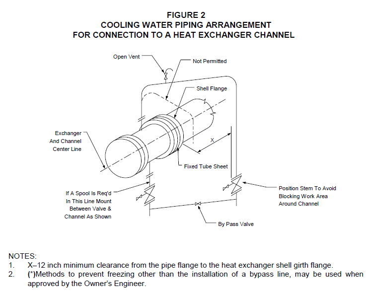
- In areas where freezing can occur, bypass piping as shown in Figure 2, shall be installed in water lines around equipment in water service, such as coolers and condensers. For most applications, an NPS 3/4 bypass line is sufficient to prevent freezing while the equipment is taken out of service for maintenance. Methods to prevent freezing during shutdowns, other than a bypass line, may be used when approved by the Owner’s Engineer.
- Air–cooled heat exchanger piping header arrangements shall be in accordance with the following:
- Inlet piping to a heat exchanger unit, which is made up of multiple bays with incoming two–phase fluids in flow regimes other than the dispersed or bubble flow region (per the Baker flow map), shall have a symmetrical piping arrangement consisting of multiple cascading headers to equalize the flow to each bundle; see Figure 3A.
- Single–phase–flow headers may be arranged as a simple rake– or comb–shaped manifold, see Figure 3B, if the pressure drop ( P x) from the header inlet to the most distant nozzle of the last heat exchanger in the row is approximately 1/9 of the pressure drop ( Py) through that exchanger.
- Inlet and outlet headers shall not be located over or under the tube areas.
- Expansion of the header shall be provided for by permitting bundles to slide in their frames.
FIRED HEATERS PIPING ARRANGEMENT
- Piping adjacent to fired heaters shall remain clear of all access and observation openings and the space required for the tube and burner maintenance.
- Additional requirements for piping arrangement at fired heaters are covered in EP 5–6–3.
ROTATING EQUIPMENT PIPING ARRANGEMENT
- Piping shall not obstruct removal of pump or turbine cases, pump rods, compressor pistons, or other rotating equipment components.
- Additional requirements for piping arrangement at rotating equipment are covered in EP 5–6–2.
STRAINER PIPING ARRANGEMENT
- The design and selection of strainers for equipment shall be in accordance with EP 5–4–5.
- Piping layout shall permit insertion and removal of temporary strainers without disturbing equipment alignment. Pipe fittings such as Tee’s, “Y”’s, or fabricated piping spool pieces are acceptable for this purpose.
- The design and location of permanent strainers shall permit cleaning without removing the strainer body.
STORAGE TANK AND STORAGE VESSEL PIPING ARRANGEMENT
- Above ground piping either extraneous or associated with tanks or vessels shall not run through separately diked areas of other tanks or vessels. However, piping at atmospheric storage tanks within a group may cross intermediate toe walls within that group.
- Pumps and piping manifolds shall be located outside the diked area, except pumps may be located within the diked area to limit the suction line pressure drop of heavy viscous stock. In such cases, remote shut–off facilities shall be provided outside the diked area.
- Ancillary equipment for the operation of the storage tanks such as air eliminators, filters, refrigeration equipment and air-cooled heat exchangers shall be located outside the diked area. The location of shell and tube exchangers shall be governed by the following:
- Exchangers integral with the piping system may be located within the diked area for atmospheric storage operations.
- Exchangers associated with refrigerated storage operations shall be located outside the diked area.
- Process unit feed tanks shall have separate filling and discharge systems to avoid sending slugs of water to the process units.
- A protective coating system, as for Underground Steel Pipe, shall be applied to portions of piping passing through dikes or dike sleeves. A sleeve is required where pipes pass through concrete dikes. The annular space between pipe and pipe sleeve shall be sealed to prevent dike leakage. A sliding joint packed with fire retardant material or bellows joint (between pipe sleeve and outside surface of process pipe) may be used. Sleeves shall be provided with low point drain holes. For horizontal installations, drain holes shall be located near each end of the sleeve.
- Additional requirements for piping arrangement at storage tanks and vessels are covered in EP 5–6–1.
15.0 STEAM SYSTEM PIPING ARRANGEMENT
Specific arrangement and layout requirements for steam piping systems are covered in EP 5–6–6.
16.0 PRESSURE RELIEF SYSTEM PIPING ARRANGEMENT
Specific arrangement and layout requirements for pressure relief piping systems are covered in EP 5–6–4.
INSTRUMENT AND CONTROL VALVE PIPING ARRANGEMENT
- Arrangement and layout requirements for instrument piping systems and control valve manifolds are covered in EP 5–6–5.
- Where fire protection is specified for lines containing flange-less control valves, the protection shall cover the valve, shall be replaceable and not interfere with the operation of the valve, position indicators and other accessories.
- (*)Control valves for steam heated reboilers shall be located in the steam lines, not in the condensate lines, unless otherwise approved by the Owner’s Engineer.
UTILITY STATION LOCATION AND ARRANGEMENT
- (*)Separate utility stations for water, steam, nitrogen or air shall be provided in or near working areas where significant maintenance work or operational clean–up will be required. These areas shall be identified by the Owner’s Engineer. A single 50-foot length of hose shall reach the working area from such stations. The utility commodities shall be provided in working areas as follows:
- Provide water in pump areas and near equipment that will be water washed during maintenance. Water will be provided at grade level only.
- Provide steam in areas subject to product spills and near equipment that requires steaming out during maintenance. Steam will generally be provided at grade level only. Elevated and/or additional requirements will be shown on utility flow diagram.
- Provide nitrogen in all areas requiring nitrogen for purging of equipment of hydrocarbons.
- Provide air in all areas requiring air for air driven tools. Typical working areas would be at exchangers, both ends of heaters, compressor house, manway levels at columns, platform level around top of reactors.
- Air for breathing shall only be drawn from dedicated breathing air systems that are totally divorced from all other utilities.
- Where possible, the three services should be grouped at grade level. Hose racks, hose and quick coupling attachments will not normally be provided.
UNDERGROUND PIPING LOCATION AND ARRANGEMENT
- (*)Unless otherwise specified by the Owner’s Engineer, all hydrocarbon piping shall be placed abovegrade. Where they must be buried, their location shall be marked by signs spaced along the route of the line (similar to the way underground high–voltage power cables are marked).
- The following requirements should be considered when designing and laying out underground piping systems:
- Drain hubs should be provided at all equipment except that equipment whose contents flash at atmospheric temperature or equipment that carries water or highly viscous materials (e.g. slurry).
- Miscellaneous small-bore drains that are used infrequently do not require hubs, as long as there is a hub within 50 feet and they can be serviced with a hose. Sanitary tees should be used instead of laterals in free flowing sewers to eliminate the need for additional fittings.
- Provisions should be made for the removal of foreign matter that may block a sewer.
- Main lines should be rodded or flushed between sewer boxes.
- Branch sewer lines that terminate at main sewers may be rodded or flushed from the hub where they originate.
- When the cumulative total of bends in a sewer line through which rodding or flushing is performed exceeds 180 , an additional cleanout must be provided.
- Cleanouts for branch sewers should be located more than 100 feet apart.
- Water lines located below grade should have the water level of the pipe below the frost line or be provided with means to prevent freezing. Fire water and stagnant water lines should be located with the top of line below the frost line as a minimum.
- When located below grade, piping provided with protective heating and piping in services requiring inspection and servicing, should be in trenches. Other piping should be buried in earth. Minimum cover for buried piping shall be 12 inches.
- Buried pipe crossing under roads should be provided with adequate cover designed for the following loading:
- A truck single axle of 32,000 lb. applied as wheel loads (an axle consists of 2 sets of tandem wheels spaced 6 feet between tandem centers).
- The contributory weight of cover and road materials.
- Piping under railroad tracks or roadways not on the Owner’s property shall be installed in steel pipe sleeves. The sleeves for these lines shall be vented and shall conform to the requirements of the railroad or highway department involved.
- Lines under roads and railroads shall have sleeves only if the pipe wall thickness is too light to support the wheel and fill loads. At least 12 inches of cover shall be provided for unsleeved lines under roads and railroads. For railroads, the 12 inches is measured from bottom of ties to top of pipe.
- All bare lines and all pipe sleeves (installed by trenching) located underground and through earth firewalls shall be protected against soil corrosion in accordance with EP 10–3–3.
- Underground piping located outside a plant (for example, lines under public roads and railroads) requires special consideration with regard to corrosion protection. Some of the precautions that may be necessary include:
- Electrical insulation should be installed in the flanged joints on both sides of public roads and railroads.
- Concentric supporting electrical insulators and centering cradles should be installed in sleeves under public roads and railroads. Seal the ends of the sleeves with WmSon Z– seals.
UTILITY CONNECTIONS TO PIPING AND EQUIPMENT
- (*)Unless otherwise specified by the Owner’s Engineer, utility connections to process piping and equipment shall be distinguished as follows:
- Utility connections to process piping and equipment that are to be used during plant operation shall be per Figure 4.
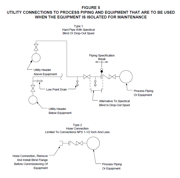
- Utility connections to process piping and equipment that are to be used when the equipment has been isolated for maintenance shall be per Figure 5.
- Materials for valves and connective piping shall be suitable for the more corrosive condition of the process or utility service, see Figure 4 and Figure 5 for the typical location of the piping specification break.
- For unlined equipment, the pressure temperature rating of the valves and connective piping shall be suitable for the more severe line classification of the process or utility service, see Figure 4 and Figure 5.
- For lined equipment, the pressure temperature rating of the valves and connective piping shall be suitable for the calculated or demonstrated metal temperature of the connective piping or equipment, and the more severe design pressure of the process or utility service. The maximum metal temperature shall be determined from heat transfer considerations taking into maximum utility flow and no utility flow.
- (*)Block and check valves shall be located adjacent to the piping system or equipment. If operator access to the utility connection is not provided, the block and check valve shall be located at the closest position where access exits. This alternative location is subject to the approval of the Owner’s Engineer.
- Utility inlet connections to internals inside piping or equipment (for example, tube bundles and coils) shall be permanently piped as shown in Figure 4. The utility system upstream from the process equipment through the first block valve and check valve shall be suitable for the design pressure and temperature of the equipment as well as the design pressure and temperature of the utility.
- Utility systems, including auxiliaries such as steam traps, connected to the outlet from internals inside piping or equipment shall be suitable for the design pressure and temperature of the equipment as well as the design pressure and temperature of the utility. When the block valve is installed upstream of a steam trap, or when the utility system extends to other piping or equipment, the remainder of the utility system shall be suitable for the design pressure and temperature of the equipment, or protected with a pressure relief device.
- Connections between piping systems carrying a potable water supply and other piping systems or equipment containing non–potable water or process fluids shall be made by using a break– tank or reservoir with an air gap, and/or a reduced pressure type backflow preventer. The method used to prevent back–siphonage shall comply with the requirements of the local jurisdiction’s plumbing code, and is subject to the approval of the Owner’s Engineer.
*
VENTS, DRAINS, AND BLEED VALVES
- Low point drains and high point vents shall be provided for pressure testing.
- The need for valving vents or drains, and drain piping, shall be based on service and operation as shown in Table 5.
- (*)Discharge piping required from valved vents and drains normally or frequently in an open position shall be as follows:
- Toxic and highly corrosive materials shall be piped into a closed drain system appropriate for the fluid properties. For example: phenol shall be tied into a separate collection system, acidic or caustic wastes may require neutralization or other treatment before discharge to the sewer system.
- Discharge arrangements for flammable materials and combustible liquids shall be reviewed with the Owner’s Engineer.
- If a condensate return system is not provided, piping may terminate at a steam trap, provided discharge will not be into walkways or other areas frequented by operating personnel.
21.3.1 Other non–dangerous material discharge may terminate at the drain valve.
- If vents are not specified to be piped back to suction, pumps handling non–dangerous materials shall be vented, via a valved vent line, to discharge at the base plate or to an open drain.
- Packing vent, distance piece vent, and distance piece drain piping in toxic and flammable material services shall be installed as follows:
- Vents and drains shall be separately piped to prevent mixing of gases or backflow from vent or drain system.
- Air and flammable material vent and drain lines shall not be piped together.
- Headers for draining distance piece and packing vents shall not be used for interstage condensate trap discharge.
- An oil knock–out pot shall be included in the vent line from the packing. Each distance piece drain line shall include a liquid—seal–the depth of seal to be at least 6 inches.
- Packing vent lines shall be equipped with 3–way valves to permit leakage monitoring.
- For services containing more than 5000 ppm H2S, signs (black letters in yellow background), as shown below per ANSI Z35.1, shall be permanently mounted at or near the bleed valves with the following legend. This identification is required at any bleed connection on the associated equipment side of a block valve provided that:
- The equipment is subject to onstream bypassing (or removal), and
- The bleed connection is not piped to a closed system.
FLUSHING AND CLEANING CONNECTIONS
- Connections using steam, water, air, or inert gas from the utility stations shall terminate in a connection mating to that provided on the utility hose. Different connections must be provided for each utility.
- (*)For new work in existing plants, “quick–type” couplings shall be per Owner’s standard (i.e., type or catalog number). Details will be furnished by the Owner’s Engineer. Each utility shall have a unique connection.
- In fluidized solids or slurry services, if flushing of piping is specified, flushing and drain connections shall be located to minimize unflushed “dead–leg” sections. Flushing connections shall be located as closely as practicable to block valves and equipment flanges.
- Where equipment flushing is specified, discharge piping from valved vents and drains shall be provided with flushing connections located next to the valves.
- (*)When heat exchanger cleaning connections have been specified by the Owner’s Engineer, they shall satisfy the following:
- Chemical cleaning connections shall be installed in the connecting piping to individual heat exchangers if the inlet and outlet nozzles are less than NPS 4. For nozzles larger than NPS 4, chemical cleaning connections shall be installed on the heat exchanger nozzle per EP 8–1–1, EP 8–1–4, EP 8–1–5, EP 8–1–6 and EP 8–1–7.
- Where chemical cleaning connections are to be made in the piping, a flanged spool piece shall be installed next to the exchanger nozzle.
- Connections shall be NPS 1–1/2 and flanged, installed horizontally, and located at a minimum distance from mating exchanger flanges; however, connections shall not interfere with bolt removal.
- For heat exchangers in series or series–parallel arrangement, one chemical cleaning connection shall be provided at the inlet nozzle and one at the outlet nozzle of each series group.
- (*)The four (4) principle media used for purging and flushing of hazardous material from process plant, offsites pipework, and tankage are: Steam, Inert Gas, Water and Air. The choice of purging media depends on both the nature of the hazardous substance, and the characteristics of the purging media. The benefits and restrictions of each of these four media are discussed below to aid in their selection. In addition where and where not to use each of the purging media are shown in Table 6. The requirements of Table 5 shall be followed unless alternative purging and/or flushing media is approved by the Owner’s Engineer.
- Steam - Steam is considered the most effective medium for purging process equipment completely of flammable and toxic materials. The heat effect readily vaporizes volatile materials and reduces the viscosity of heavy components, particularly if “closed” steaming is carried out when it is possible to increase the pressure/temperature inside the equipment being purged. However, the thermal effect of steam can be harmful if equipment is heated to a point outside it’s safe pressure/temperature envelope (e.g. if vents and drains are inadequate or blocked), or where there is no allowance made for expansion as the equipment/pipework heats up. Another issue is the disposal of large quantities of steam condensate containing hydrocarbons to drain during the steaming process, which may have NESHAPs or other similar considerations.
- Inert Gas - Inert gas normally used in liquid fuel plants is nitrogen. It is used at ambient temperature, and at pressures up to 100 psig. The use of inert gas to purge a system does not always succeed in removing all harmful materials if they are contained in liquid or solid residues remaining in the system. It is necessary to keep the oxygen content below 12% in an inerted space to prevent ignition of hydrocarbons. The other major disadvantage with using nitrogen is that it is also non–life sustaining; there are numerous case histories of fatalities caused by asphyxiation to people working on inerted equipment and piping. Carbon dioxide is also used as an inert gas in some specialized cases. It possesses an additional hazard of creating a corrosive acidic environment in the presence of free water.
- Water - Water is often used to clean long lengths of pipelines that cannot be effectively purged with steam or inert gas. This normally applies to off–sites pipework rather than piping on a process unit. It is not effective in removing viscous oils or waxy, or similar, deposits unless extremely high velocities are used, as in water jetting. Water is also very heavy and unless the pipelines are designed to run liquid full (s.g. = 1.0), water may not be an option. It is also unadvised to carry out any hot work on pipework or equipment that has been purged only with water. Water has one other undesirable property; it freezes at 32oF - necessitating removal of water from purged systems during cold weather.
- Air - Air is generally used to purge storage tanks of flammable and toxic materials during removal of sludge; as sludge is distributed it gives off gasses which can build up to unsafe levels if not continuously removed by purging. Sufficient velocities must be maintained by air movers to prevent the build up of such a mixture and atmosphere monitoring maintained. Air is also used on process units to maintain safe atmospheres inside equipment which is being cleaned of sludge or other deposit, or where the maintenance or inspection procedure (i.e., welding, dye penetrant, crack detection) releases harmful materials, or where conditions may give rise to an oxygen deficient atmosphere (e.g. wet steel).
TEMPORARY PIPING
- Unless accepted as an integral part for preparing the plant for maintenance (e.g., steam or nitrogen purge), all temporary piping irrespective of scale or permanency, shall be reviewed through an appropriate management of change program in accordance with EP 3–5–3.
- All piping designated as temporary in accordance with this Practice shall be designed in accordance with the applicable provisions stipulated in EP 5–1–1.
24.0 TABLES
TABLE 1 CLEARANCES FOR PIPING
| LOCATION | MINIMUM VERTICAL CLEARANCE (ft) |
MINIMUM HORIZONTAL CLEARANCE (ft) |
|---|---|---|
| Clearance from centerline of major roads open to unrestricted traffic (such as periphery of process unit area limits) | 22 | 12 |
| Clearance from centerline of railroads (top of rail for vertical) | 22 | 8.5 |
| Within process unit areas clearance from centerline of internal roadways for access of maintenance and firefighting equipment | 16 | 8 |
| Under pipeways | 12 | N/A |
| Clearance from centerline of walkways and elevated platforms | 8 | 1.5 |
| Between two or more tiers of pipe | 2 | N/A |
| Under any low level piping in paved or unpaved areas. | 1 (1) | N/A |
NOTE:
(1) Measured to bottom of pipe disregarding flanges and insulation.
TABLE 2
BLOCK VALVE REQUIREMENTS AT UTILITY HEADERS
| SERVICE | BLOCK VALVE REQUIREMENTS (1) |
|---|---|
| Steam | Provide block valves at header for all supply and user branches. A turbine inlet and exhaust valve shall be located at the turbine and not at the header. |
| Condensate | Provide block valves at the header. |
| Cooling Water | Block valves at the header shall not be provided for cooling water. Block valves shall be provided at each equipment connection. |
| Nitrogen | Provide block valves at the header. |
| Instrument and Utility Air | Provide block valves at the header. |
| Service Water | Provide block valves at the header. |
NOTE:
(1) Header block valves shall be provided for all services when the branch connection is NPS 2 or less.
TABLE 3
REQUIREMENTS FOR THE INSTALLATION OF EMERGENCY BLOCK VALVES
| EQUIPMENT | REQUIREMENTS |
|---|---|
| Vessels | An emergency block valve shall be provided on all lines below the low liquid level of a vessel or tank with an inventory at a normal operating level of 2000 US gallons or greater when one of the following is true: The liquid conforms to NFPA No. 321, Class 1, or a Class 2 or 3 liquid held above its flash point. The liquid is toxic. The temperature is 410F or higher. |
| Tanks | Tanks with separate inlet and outlet nozzles - Tanks with a capacity of 5000 barrels and larger which store Class 1, 2 and 3 fluids shall have a Type 4 EBV installed on each of the tank outlet nozzles. In addition, a block and check valve shall be installed on each of the tank inlet nozzles. Tanks with common inlet and outlet nozzles - Tanks with a capacity of 5000 barrels and larger which store Class 1, 2 and 3 fluids shall have a Type 4 EBV installed on each of the tank common inlet and outlet nozzles. |
| Compressors | Emergency Block Valves (EBV’s) are required in the suction and discharge lines of any compressor over 200 horsepower. For compressors meeting the criteria in (1.) above which have multiple suctions or discharges connected to different services, EBV’s are required in all common suction and discharge lines that are normally open. For compressors meeting the criteria in (1.) above, which have interstage circuits (e.g. condensers and knock out drums), EBV’s are required in the suction and discharge lines between stages if the interstage equipment contains more than 1000 US gallons of a Class 1 liquid at the normal operating level. |
TABLE 3 (CONTINUED)
REQUIREMENTS FOR THE INSTALLATION OF EMERGENCY BLOCK VALVES
| EQUIPMENT | REQUIREMENTS |
|---|---|
| Compressors (Cont.) | For discharge lines with a pressure rating Class 600 and less, a high performance check valve can be utilized in lieu of an EBV for emergency isolation. A high performance check valve is defined as a fire–safe valve which provides a tight shut–off design which can maintain seating capability in normal service and during process upset conditions. For reciprocating compressors, the check valve shall be a non–slam design to minimize seat damage; a nozzle check valve (Mokveld or equivalent) is recommended for this service. The design of the check valve used in lieu of an EBV is subject to the approval of the Owner’s Engineer. Minimum requirements for the Type of EBV shall be as follows: For 200 to 1000 horsepower compressors, a Type 2 or Type 3 EBV is required based on line size; however, a Type 4 EBV is recommended. For over 1000 horsepower compressors, a Type 4 EBV is required. |
| Fired Heater | EBV’s located in pump and compressor systems upstream of fired heaters shall be located to effect upstream isolation of the heater. Outlet lines for fired heaters that handle Class 1, 2, or 3A liquids shall be provided with a check valve. |
TABLE 4
EMERGENCY BLOCK VALVE (EBV) TYPES
| TYPE | DESCRIPTION |
|---|---|
| 1 | Manually operated block valve located at an equipment nozzle |
| 2 | Manually operated block valve located in the piping system |
| 3 | Motor or pneumatically operated block valve located in the piping system with the actuator button mounted on the actuator |
| 4 | Motor or pneumatically operated block valve located in the piping system with remotely located actuator buttons |
TABLE 5
REQUIREMENTS FOR VALVING OF VENTS AND DRAINS
| TYPE OF SERVICE | OPERATIONAL REQUIREMENTS | OPERATIONAL REQUIREMENTS | OPERATIONAL REQUIREMENTS |
|---|---|---|---|
| Normally or frequently in an open position | Startup and shutdown, or taking equipment out of service | Used only for pressure testing | |
| Dangerous Materials | Vents and Drains installed on piping, equipment and instruments shall be valved. (1)(2) |
Vents and drains shall be valved and either plugged, capped, or blinded.(2) |
Vents shall be plugged, capped, or blinded. |
| Drains shall be valved and either plugged, capped, or blinded. |
|||
| Steam under ASME/ANSI Class 150 Rating | Vents and Drains shall be valved. | Vents and Drains shall be valved. | |
| All other non–dangerous | Drains shall be valved | Drains shall be valved | Drains shall be valved |
| materials | per EP 5–3–1.Vents | per EP 5–3–1.Vents | per EP 5–3–1.Vents |
| shall be plugged, | shall be plugged, | shall be plugged, | |
| capped or blinded. | capped or blinded. | capped or blinded. |
NOTES:
- See paragraph 21.3 of this Practice for vent and drain discharge piping requirements.
- (*) When specified by the Owner’s Engineer, double block valves with a bleed connection shall be used for Dangerous Materials in accordance with the requirements stipulated in EP 5–3–1.
TABLE 6 PURGING/FLUSHING MEDIA SELECTION
| Purging/Flushing Media | Equipment Being Purged/Flushed | Use Media Where |
|---|---|---|
| Steam | Process unit equipment and piping | Temperature is no problem Pressure is no problem Introducing water into system is no problem Facilities are available to dispose of condensate/hydrocarbon mixtures Heavy/viscous liquids are being handled |
| Offsites piping | - NOT NORMALLY USED | |
| Tankage | - NOT NORMALLY USED | |
| Inert Gas | Process unit equipment and piping | It is undesirable to heat up the process equipment (e.g. compressor) Introducing water into the system is a problem (e.g. cryogenic systems) Light hydrocarbons are being handled |
| Offsites piping | - Flushing with water is not possible (e.g. flare lines) | |
| Tankage | - NOT NORMALLY USED | |
| Water | Process unit equipment and piping | - NOT NORMALLY USED |
| Offsites piping | Weight is no problem Facilities are available to dispose of large quantities of waxy deposits (unless previously purged with warm oil first) |
|
| Tankage | - It is necessary to displace heavy vapors (e.g. pressure storage spheres) | |
| Air | Process unit equipment and piping | - Air is used only after purging with steam or inert gas, to keep the concentration of harmful materials released during cleaning, maintenance and inspection work within safe limits |
| Offsites piping | - Air may be used to purge heavy oil piping only (e.g. residues and asphalt) | |
| Tankage | - Air may be used during cleaning of sludge |
25.0 FIGURES
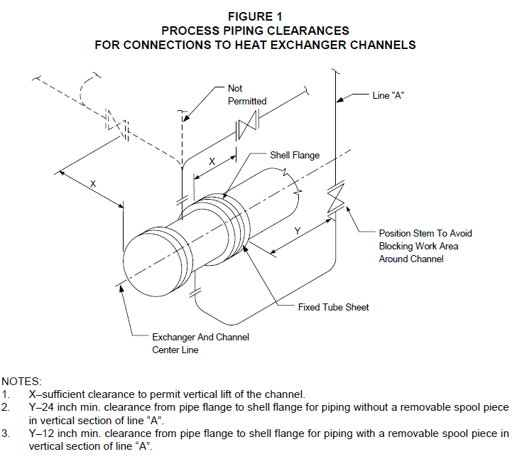
Position Stem To Avoid Blocking Work Area Around Channel
NOTES:
- X–12 inch minimum clearance from the pipe flange to the heat exchanger shell girth flange.
- (*)Methods to prevent freezing other than the installation of a bypass line, may be used when approved by the Owner’s Engineer.
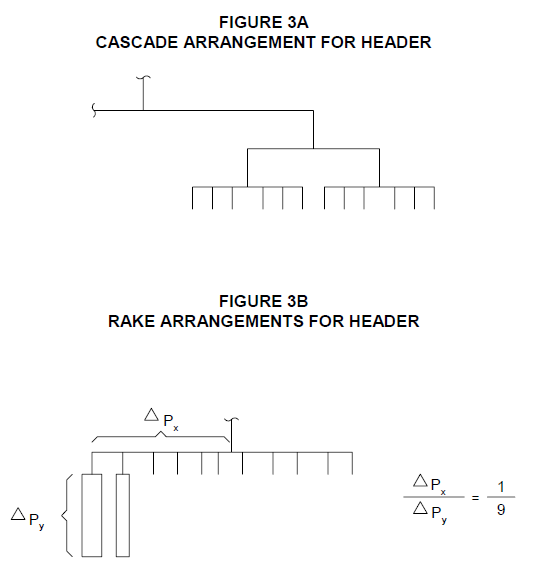
FIGURE 4
UTILITY CONNECTIONS TO PROCESS PIPING AND EQUIPMENT THAT ARE TO BE USED DURING PLANT OPERATION


Utility Header Below Equipment
NOTE:
Spectacle blind may be omitted if utility piping can be cold–springed to allow for installation of a blind flange.
© 2026 Inflection Point Engineering, LLC. All rights reserved. The content of this page — including calculation methods, reference data, written analysis, interactive tools, and source code — is the intellectual property of Inflection Point Engineering, LLC and is protected under applicable copyright, trademark, and trade secret laws. Unauthorized reproduction, redistribution, modification, or derivative use in whole or in part is prohibited without prior written consent.
Disclaimer. This material is provided for informational and educational purposes only and does not constitute professional engineering advice. Calculations, reference data, and methodologies are based on published standards and accepted engineering practice but are not a substitute for engineering judgment, site-specific analysis, or review by a licensed Professional Engineer. Inflection Point Engineering, LLC makes no warranties, express or implied, regarding the accuracy, completeness, or fitness for a particular purpose of any content presented here, and shall not be liable for any direct, indirect, incidental, or consequential damages arising from its use. Users assume all risk associated with applying this content to real-world design, operations, or decisions.
© 2026 Inflection Point Engineering, LLC. All rights reserved.